EP0285325B1 - Sonarsignalverarbeitungsgerät - Google Patents
Sonarsignalverarbeitungsgerät Download PDFInfo
- Publication number
- EP0285325B1 EP0285325B1 EP88302624A EP88302624A EP0285325B1 EP 0285325 B1 EP0285325 B1 EP 0285325B1 EP 88302624 A EP88302624 A EP 88302624A EP 88302624 A EP88302624 A EP 88302624A EP 0285325 B1 EP0285325 B1 EP 0285325B1
- Authority
- EP
- European Patent Office
- Prior art keywords
- output
- bearing
- correlator
- range
- pcc
- Prior art date
- Legal status (The legal status is an assumption and is not a legal conclusion. Google has not performed a legal analysis and makes no representation as to the accuracy of the status listed.)
- Expired - Lifetime
Links
- 238000001514 detection method Methods 0.000 claims description 51
- 230000015654 memory Effects 0.000 claims description 47
- 230000004044 response Effects 0.000 claims description 9
- 238000010926 purge Methods 0.000 claims description 7
- 238000012545 processing Methods 0.000 claims description 5
- 230000006870 function Effects 0.000 description 14
- 238000000034 method Methods 0.000 description 11
- 238000010586 diagram Methods 0.000 description 10
- 230000008569 process Effects 0.000 description 10
- IESVDEZGAHUQJU-ZLBXKVHBSA-N 1-hexadecanoyl-2-(4Z,7Z,10Z,13Z,16Z,19Z-docosahexaenoyl)-sn-glycero-3-phosphocholine Chemical compound CCCCCCCCCCCCCCCC(=O)OC[C@H](COP([O-])(=O)OCC[N+](C)(C)C)OC(=O)CC\C=C/C\C=C/C\C=C/C\C=C/C\C=C/C\C=C/CC IESVDEZGAHUQJU-ZLBXKVHBSA-N 0.000 description 8
- 238000005070 sampling Methods 0.000 description 7
- 230000008901 benefit Effects 0.000 description 5
- 230000000295 complement effect Effects 0.000 description 5
- 238000010606 normalization Methods 0.000 description 5
- 230000007480 spreading Effects 0.000 description 5
- 230000002596 correlated effect Effects 0.000 description 4
- 230000000875 corresponding effect Effects 0.000 description 4
- 230000035945 sensitivity Effects 0.000 description 4
- 230000005540 biological transmission Effects 0.000 description 3
- 238000002592 echocardiography Methods 0.000 description 3
- 238000012546 transfer Methods 0.000 description 3
- 208000019300 CLIPPERS Diseases 0.000 description 2
- 208000021930 chronic lymphocytic inflammation with pontine perivascular enhancement responsive to steroids Diseases 0.000 description 2
- 230000001427 coherent effect Effects 0.000 description 2
- 230000006835 compression Effects 0.000 description 2
- 238000007906 compression Methods 0.000 description 2
- 230000003111 delayed effect Effects 0.000 description 2
- 238000013461 design Methods 0.000 description 2
- 230000011218 segmentation Effects 0.000 description 2
- XLYOFNOQVPJJNP-UHFFFAOYSA-N water Substances O XLYOFNOQVPJJNP-UHFFFAOYSA-N 0.000 description 2
- 238000013459 approach Methods 0.000 description 1
- 230000015572 biosynthetic process Effects 0.000 description 1
- 230000000903 blocking effect Effects 0.000 description 1
- 238000004590 computer program Methods 0.000 description 1
- 239000012141 concentrate Substances 0.000 description 1
- 238000007596 consolidation process Methods 0.000 description 1
- 238000005314 correlation function Methods 0.000 description 1
- 230000000694 effects Effects 0.000 description 1
- 238000001914 filtration Methods 0.000 description 1
- 230000006872 improvement Effects 0.000 description 1
- 238000003780 insertion Methods 0.000 description 1
- 230000037431 insertion Effects 0.000 description 1
- 238000013178 mathematical model Methods 0.000 description 1
- 238000005259 measurement Methods 0.000 description 1
- 230000008450 motivation Effects 0.000 description 1
- 238000013139 quantization Methods 0.000 description 1
- 230000009467 reduction Effects 0.000 description 1
- 238000000926 separation method Methods 0.000 description 1
- 238000004088 simulation Methods 0.000 description 1
- 230000002123 temporal effect Effects 0.000 description 1
- 230000000007 visual effect Effects 0.000 description 1
Images


Classifications
-
- G—PHYSICS
- G01—MEASURING; TESTING
- G01S—RADIO DIRECTION-FINDING; RADIO NAVIGATION; DETERMINING DISTANCE OR VELOCITY BY USE OF RADIO WAVES; LOCATING OR PRESENCE-DETECTING BY USE OF THE REFLECTION OR RERADIATION OF RADIO WAVES; ANALOGOUS ARRANGEMENTS USING OTHER WAVES
- G01S15/00—Systems using the reflection or reradiation of acoustic waves, e.g. sonar systems
- G01S15/02—Systems using the reflection or reradiation of acoustic waves, e.g. sonar systems using reflection of acoustic waves
- G01S15/06—Systems determining the position data of a target
- G01S15/42—Simultaneous measurement of distance and other co-ordinates
-
- G—PHYSICS
- G01—MEASURING; TESTING
- G01S—RADIO DIRECTION-FINDING; RADIO NAVIGATION; DETERMINING DISTANCE OR VELOCITY BY USE OF RADIO WAVES; LOCATING OR PRESENCE-DETECTING BY USE OF THE REFLECTION OR RERADIATION OF RADIO WAVES; ANALOGOUS ARRANGEMENTS USING OTHER WAVES
- G01S7/00—Details of systems according to groups G01S13/00, G01S15/00, G01S17/00
- G01S7/52—Details of systems according to groups G01S13/00, G01S15/00, G01S17/00 of systems according to group G01S15/00
- G01S7/523—Details of pulse systems
- G01S7/526—Receivers
- G01S7/527—Extracting wanted echo signals
- G01S7/5273—Extracting wanted echo signals using digital techniques
Definitions
- This invention relates to a sonar system for detecting signals reflected from objects which are insonified by a transmitted sonar pulse, comprising: a first sonar receiver and a second sonar receiver with fundamentally different characteristics for simultaneously processing said reflected signals, the first and second receivers providing output signals corresponding to said objects at first and second false alarm rates at their respective outputs; and means for combining the outputs of the first and second receivers to provide an, output signal having a lower false alarm rate than those provided by the first and second receivers individually.
- sonar signals from targets have been detected by using a receiver in conjunction with an operator by whom signals observed on a display are determined to be reflected signals from objects as distinguished from signals produced by reverberation or noise produced by the ocean or by the ship on which the sonar is being carried.
- an active receiver which will provide a presentation of reflecting objects with high probability of detection while at the same time providing a presentation on the display from other than a reflecting object with low probability.
- US-A-3 723 952 describes a sonar system of the kind defined hereinbefore at the beginning in which the system is adapted to operate as a depth sounder so that it measures the distance between the ocean surface and the ocean floor.
- the reflection strength of the ocean floor is a function of its angle of inclination.
- the depth sounder projects an acoustic beam that has side lobes as well as a main lobe. Consequently a sloping ocean floor may give a reflection of a side lobe that is stronger than the reflection of the main lobe. Also the side lobe reflection may arrive before the main lobe reflection.
- the sonar system described in US-A-3 723 952 therefore incorporates an angle deviation indicator that generates a signal magnitude that is proportional to the angular difference between the angle of arrival of an incident acoustic echo signal phase front and a predetermined normal, thereby distinguishing between main lobe echoes, which are normal to the receiving device, and side lobe echoes. Only those echo signals which have an arrival angle within a predetermined sector are used to activate a time measurement means.
- a split beam receiving array is used, and each half beam is sufficiently wide to encompass several side lobes of the received beam. The array is designed to achieve spatial separation between the phase centres of the two half beams.
- the phase of the signal outputs of the two half beams is proportional to the relative bearing angle of an incident echo signal.
- One receiver of the system comprises a replica correlator receiver which is used to provide the input echo data signal to a gating circuit.
- the other receiver comprises the bearing deviation indicator, which incorporates a clipper correlator fed by two outputs of a beam former through respective filters and ⁇ /4 phase shifters of complementary sign.
- the output signal from the clipper correlator is a signal of which the magnitude e is related to the deviation angle by a relationship which includes the received signal power magnitude, noise power magnitude, input bandwidth, and arithmetic centre frequency.
- the signal magnitude e is thus proportional to the angular difference between an arriving signal phase front and a predetermined normal and is passed through a low pass filter (integrator) to a threshold detector.
- the output of the threshold detector inhibits the gating circuit only when the signal magnitude e is higher than its value for small deviation angles.
- Only echo signal data for echoes received within a defined small sector about zero deviation from the predetermined normal are passed through the gating circuit.
- US-A-3 622 963 describes a polarity coincidence correlator for determining the direction of an object from a set of transducers.
- the polarity coincidence correlator is coupled to receive output signals from two separate transducers or sets of transducers so arranged that only if an echo is travelling horizontally, do both transducers or sets receive the echo simultaneously.
- the correlator utilizes correlator circuits in the form of exclusive OR circuits, and inserts a delay in the output channel from one of the transducers or sets of transducers.
- a voltage controlled oscillator is used to shift the signal through a first delay device, and a fixed frequency oscillator is used to shift the partially delayed signal through a second, tapped delay device. Feedback is used to vary the frequency of the variable frequency oscillator in such a way as to provide a signal representative of the direction of the echo.
- a sonar system of the kind defined hereinbefore at the beginning is characterised in that the first receiver includes a segmented replica correlator; the second receiver includes a polarity coincidence correlator; and the combining means selects one of the respective outputs of the receivers to provide an output signal having a lower false alarm rate than those provided by the first and second receivers individually.
- a preferred embodiment of the invention comprises two fundamentally different detection processes operating simultaneously with the output of each detection process being combined by a computer utilizing a computer-aided detection algorithm.
- One detection processor is a segmented replica correlator (SRC) and the other detection processor is a polarity coincidence correlator (PCC).
- SRC segmented replica correlator
- PCC polarity coincidence correlator
- the SRC disclosed herein is a modified replica correlator operating on a full sum beam output.
- the PCC is a split beam cross-correlator.
- Each detection processor provides to the active computer-aided detection algorithm a list of ranges and bearings of a relatively small number of potential detection events.
- the computer algorithm operates on these events to compare events from the current ping and the previous pings from each of the processors to provide output detection events from reflecting objects free of clutter events.
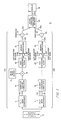
- the system 10 of this invention which employs simultaneous coherent and incoherent processor channels 100, 200, respectively, for sonar signals is shown in FIG. 1.
- the active receiver comprises two fundamentally different detection processes operating simultaneously upon sonar signals provided by beamformers 11, 12 connected to a transducer array 13.
- One detection processor is a segmented replica correlator (SRC) 14 and the other detection processor is a polarity coincidence correlator (PCC) 15.
- SRC is essentially a replica correlator, discussed more fully subsequently, operating on a full sum beam output provided by beamformer 11. Hard limiting on the input line 140 of SRC 14 is used for precise amplitude normalization.
- the SRC 14 is a temporal correlator with pulse compression and provides its best performance when acoustic conditions are good in the ocean environment.
- good conditions are meant low multipath and target distortions and low spreading by the ocean medium of the transmitted and received signal in both time and frequency.
- the polarity coincidence correlator (PCC) 15 is a split beam cross-correlator which also uses hard limiting for precise amplitude normalization at its inputs 150, 151 provided by the left- and right-half outputs of the split beam beamformer 12. Under good acoustic conditions as described above, its performance is inferior to the SRC; however, under poor conditions, it will out-perform the SRC because it is insensitive to distortions of the transmitted signal by the acoustic conditions.
- the PCC 15 is simply a plane wave sensitive energy detector and does not pulse compress.
- the SRC 14 and the PCC 15 receivers have complementary characteristics that are utilized in this embodiment of the invention to improve the detection performance of the system/operator.
- the receiver system 10 capitalizes on these complementary characteristics in the following way: when acoustic conditions are good, the superior performance of the SRC is provided as an output to the display 16. When acoustic conditions are poor, the best performance allowed by the conditions is provided by the PCC 15 to the display 16.
- Another characteristic which is employed in this system is that studies of sea data show that these two fundamentally different receivers 14 and 15 rarely produce a false alarm (i.e. an apparent signal with no signal present) at the same range and bearing.
- the SRC 14 performs poorly against extended targets such as ridges. It tends to produce outputs only on prominent features of the extended target.
- the PCC 15, on the other hand, performs well against the same extended targets and will provide threshold excess at all ranges and bearings spanned by the target.
- the two receivers 14, 15 can be used to sort out extended, non-moving targets from moving targets by utilizing their complementary detection capabilities on these two types of targets.
- the segmented replica correlator 14 has its output provided to a mean value source 17 whose value is provided with the appropriate polarity to a summer 18 for removal of the mean value of the SRC 14 output before being provided to a post detection filter 19.
- the mean output of the SRC 14 is substantially constant under most conditions and therefore the mean output of SRC 14 may be removed by a fixed value from source 17. There may exist some small perturbations on the SRC 14 mean output, and a simple high-pass filter for post detection filter 19 is adequate to remove these perturbations.
- the output of PCC 15 is provided to post detection filter 20. Post detection filter 20 is discussed subsequently, but its primary purpose is also the removal of the mean value of the signals provided by the correlator 15.
- the bearing interpolators 21, 22 operating on the output signals provided by post detection filters 19, 20 have as their purpose the decrease in the bearing quantization resulting from each beam of beamformers 11, 12 of the detected signals shown on the display 16.
- Each bearing interpolator 21, 22 has three signals on lines 191, 192, 193 and lines 201, 202, 203, respectively, upon which it operates. Interpolators 21, 22 provide an output signal on lines 210, 220, respectively, which has a bearing quantized by a smaller amount than that provided by only the signal on lines 191, 201 which is the result of one beam formed by beamformers 11, 12, respectively.
- the signals on lines 192, 193 are provided by the SRC's to the immediate left and right of the SCR coupled to line 191 using the beam formed by beamformer 11.
- the signals on lines 202, 203 are formed by the PCC's adjacent to the PCC coupled to line 201 using the left-and right-half beams formed by beamformer 12.
- the design of the post detection filters 19, 20 and the bearing interpolators 21, 22 is also well known to those skilled in the art.
- the outputs of interpolators 21, 22 are applied to threshold circuits 23, 24, respectively, which are individually thresholded by threshold levels 25, 26 to provide from each threshold circuit 23, 24 a P FA ⁇ 10 exp (-4).
- the P FA is set to this low value so that on a given range sweep, only a few non-acoustic events (false alarms) will be produced by each detection processor 14, 15.
- This low value of P FA can only be guaranteed by the use of hard limiting at the input for precise amplitude normalization and the use of wide band FM transmitter signal for precise normalization of the input bandwidth for both reverberation and noise limited backgrounds.
- Each detection processor 14, 15 ultimately provides on lines 401, 402, respectively, to a computer 40 utilizing a computer-aided detection algorithm (ACAD) a list of ranges and bearings of a relatively small number of events.
- ACAD computer-aided detection algorithm
- the computer 40 further reduces the number of events on its output line 403 to the display 16.
- circuitry of FIG. 1 shows only one SRC channel 100 and one PCC channel 200 for only one receiving beam.
- the number of SCR 100 and PCC 200 channels would be that number required to cover the desired bearing sector, and these channels would be provided by time-multiplexing of the circuit elements of FIG. 1 in the manner known to those skilled in the art.
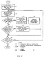
- FIG. 2 is a flow diagram of the ACAD algorithm.
- the algorithm is explained as follows: The inputs to the algorithm are four lists of events. Two of the lists represent the events for the current transmission and reception (a ping) and the previous ping for one of the processors 14, 15. The other two lists are the events for the current and previous pings of the other processor. This process is shown as the contents of rectangle 31 wherein the step of transferring the current ping list to the previous ping list for both the SRC and PCC receivers is indicated when it is time to generate a new "current" list.
- the first step is to determine if the current ping lists for the SRC and PCC processors indicate the occurrence of events at the same range intervals.
- Rectangle 32 shows the step of selecting targets from the information provided in the current list with the PCC list being scanned first and the SCR list secondly. Both lists could be scanned simultaneously as an alternate mode of operation.
- the decision block 33 performs the comparison of the current ping lists of the PCC and SRC receivers to provide an output on line 330 if there is concurrence.
- Block 34 indicates that the current list of the SCR is purged of all target indications which occur at the same range interval within plus or minus 45°. Block 34 eliminates the phenomenon called "bearing spreading".
- the SRC processor being a sum beam processor, will tend to produce target events on beams whose sidelobes are in the direction of the target at extremely high signal-to-noise ratios.
- the PCC receiver with proper beam shading, never produces bearing spreading. If the SNR is high enough to produce bearing spreading on the SCR, then it is highly likely that the PCC will also detect a target. Hence, the PCC output can be used to purge the SRC output of spurious events.
- the output of the purged SRC current list is provided to block 35 which indicates the transfer of the SRC target indications to the display device 16 of FIG. 1.
- the next step in the detection process is to compare each event in the current ping list to the events of the previous ping list for each of the receivers.
- This decision processing is indicated by the decision block 36 in which it is determined whether the target indication is geographically consistent with the previous ping of either receiver. If the answer is yes, then block 37 causes the transfer of both the current and previous target indications to the display 16.
- an event is displayed if there is "geographical consistency"; that is, events in the previous and current ping lists that are very close in range and bearing and likely to come from a target constrained in relative speed.
- This detection decision rule has been proven quite successful in target presentations using actual target data. The decision rule does, however, require a low and controlled P FA to work successfully, which is the motivation for providing both input amplitude and bandwidth normalization in the system of this invention.
- the decision block 38 indicates the next step in the process wherein in the absence of geographically consistent targets on the successive pings causes the algorithm to have a decision as to whether there exists any more target indications in either of the current lists. If the answer is that there are more target indications, the flow diagram indicates that the process begins again in the selection block 32 to select the next target indication from the current list of either of the receivers.
- the preceding algorithm is implemented by a program which controls a general purpose computer.
- a program which controls a general purpose computer.
- Such a program may be written by a programmer having ordinary skill in the art of programming.
- This preceding algorithm results in a "target only" display which frees the operator observing the display from the detection task and allows him to concentrate his attention as an evaluator in the classification process in evaluating the displayed targets.
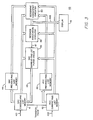
- FIG. 3 is a block diagram hardware representation of the active computer-aided target detector 40 which operates to implement the flow diagram illustrated in FIG. 2.
- SRC channels 100 and PCC channels 200 for each beam are time multiplexed and their range and bearing event outputs presented on lines 401, 402, respectively, to an SRC current ping list memory 41 and a PCC current ping list memory 42, respectively.
- SRC current ping list memory 41 and PCC current ping list memory 42 respectively.
- These memories store the range and bearing of each detected signal (an event) provided by the segmented replica correlator 14 and the polarity coincidence correlator 15, respectively.
- memories 41, 42 are transferred to memories 44, 45 to store the SRC previous ping list and the PCC previous ping list, respectively, in the memories 44, 45 prior to new target information being read into the current ping memories 41, 42.
- memory 42 is sequentially addressed and the range and bearing at each address is compared with the range and bearing at all the addresses of memory 41 to determine a coincidence in range and bearing of a stored event in both memories 41, 42.
- the receiver association circuit 46 makes the comparison, and for any coincidence in range and bearing of the contents of memories 41 and 42, circuit 46 provides a signal on line 47 to actuate purge circuit 48.
- Purge circuit 48 responds by reading out the stored events from all addresses of SCR current list memory 41 and blocking the rewriting in of those events contained in memory 41 over a predetermined bearing spread and at the same range at which coincidence was detected. This operation purges SRC memory 41 of events within a bearing sector on either side of the bearing at which coincidence in bearing and range in both the SRC and PCC memories 41, 42 was obtained.
- the receiver association circuity 46 provides an output reading of range and bearing at which the SRC memory 41 and PCC memory 42 both indicate the presence of an event or target.
- the range and bearing in digital form are provided by the receiver association circuity 46 to the display 16 which presents this data as an illuminated spot at the proper range and bearing of display 16.
- the SRC current ping list memory 41 and the PCC current ping list memory 42 are sequentially addressed and for each address of both memories 41, 42, all the addresses of SRC previous ping list memory 44 and PCC previous ping list memory 45 are read out and compared in geographic consistency circuitry 50.
- Geographic consistency circuitry 50 provides at its output 403 to display 16 the range and bearing of all events provided by either memory 41 or 42 and the range and bearing of all events provided by either memory 44 or 45 when the ranges and bearings of both are within a predetermined difference value. This operation can be accomplished by circuitry 50 taking the difference in the ranges and the difference in the bearings and comparing these differences with predetermined values in a comparison circuit.
- the geographic consistency circuitry 50 provides both events to the display 16 thereby indicating the current and previous locations of a target or event.
- the functions provided by the geographic consistency circuitry 50 and the memories 41, 42, 44, 45 are those shown in the blocks 36 and 37 of FIG. 2. Read out of the successive location of memories 41 and 42 by incrementing an address generator (not shown) for both memories 41, 42 carries out the function of decision block 37 of FlG. 2.
- the segmented replica correlator 14 with hyperbolic waveform is coupled with the PCC 15 which is a totally different kind of correlator, a plane wave correlator rather than a time correlator.
- the PCC Under conditions where the transmission medium badly distorts the received waveform, the PCC continues to function whereas the SRC performance degrades. Under good conditions where the medium does not distort, the PCC does not work as well as the SRC.
- the PCC which is a plane wave correlator, there is in the water medium what amounts to two sensors, i.e. two half beams. Anything coming in on these two sensors is cross-correlated to determine if they are the same signal. What the two sensors are doing is comparing waveforms.
- the PCC correlator doesn't care how badly distorted the waveform is, it merely cares that there is the same signal on both channels. Therefore, under bad distortion conditions, the PCC will perform very well. Where there is little distortion, the PCC will still perform but not perform as well as the segmented replica correlator.
- the SRC and PCC are obtained at base band by quadrature demodulation of the bandpassed signal having a center frequency f o .
- Sampling of this signal at a sampling frequency at least four times that of the center frequency at base band results in substantially the same loss in signal-to-noise ratio as is obtained when using analog correlation.
- Sampling of the base band signal allows a reduction in sample rate thereby allowing the received signals of many beams to be processed independently of one another by the same correlator by time multiplexing.
- the PCC has not been implemented at base band, but rather at f o (the center frequency of the modulated transmitted signal).
- the receiver system 10 of this invention utilizes a wideband FM received signal produced by a transmitter (not shown) because only wideband FM can provide simultaneous reverberation limited and noise limited performance for all dopplers.
- the most popular FM waveform currently in use in the prior art is linear FM (LFM).
- LFM linear FM
- the 3 db doppler sensitivity of a 240 millisecond pulse length, 1,000 Hz waveform is calculated as 5.56m.sec ⁇ 1 (10.8 knots).
- hyperbolic FM sometimes called “linear period modulation” (LPM) was chosen for use in this invention because it is substantially "doppler invariant".
- LFM linear period modulation
- overlap loss occurs because the peak of the correlation function formed by correlating the zero doppler replica and the doppler shifted waveform occurs when the envelopes of the signal and the replica are not coincident (i.e. doppler induced range error). This loss exists for both LFM and HFM but is small for large bandwidth-time products.
- HFM Slope mismatch occurs with LFM because doppler shift changes the frequency versus time slope of the waveform and is a major source of loss with wideband LFM.
- HFM it is always possible to match the slope by proper selection of time delay; hence, there is no slope mismatch loss.
- the major ramification of the selection of HFM is that only a single receiver is needed to cover all dopplers.
- HFM is chosen for the following reasons: HFM provides equal noise and reverberation limited operation for all target dopplers; HFM doppler sensitivity is so low that multiple doppler bank receivers are not required; and HFM can be used for both detection and classification.
- the segmented replica correlator (SRC) 14 of FIG. 1 will work for any arbitrary waveform including HFM.
- FIG. 4 shows a functional diagram of the SRC when it is implemented as a matched finite impulse response (FIR) filter operation.
- the FIR filter coefficients of the multipliers 56 connected to taps on the delay line 51 are the signal replica.
- a difference between the SRC and a matched filter is the insertion of the envelope detectors 52 at the output of the summing circuits 53 to which a small group of the multipliers provide inputs.
- the SRC 14 divides the input waveform on its input line 140 into M segments and replica correlates each segment individually; the individual correlations provided at the outputs of the summing circuits 53 are then combined in summing circuit 55 after envelope detection in detectors 52.
- the SRC provides the gain of a matched filter, i.e.
- FIG. 5 represents the normalized output mean as a function of input SNR for time-bandwidth products of 64 and 500.
- FIG. 6 is a typical plot of the mean output versus SNR for various levels of segmentation M from the simulation where the frequency was 3,760 Hz, bandwidth was 1,000 Hz, and the duration of the received signal is 0.24 seconds.
- FIG. 7 is a plot of the SRC 14 output as a function of doppler over the range of 0 to 20.58m sec ⁇ 1 (0 to 40 knots).
- the waveform is divided into M segments, each of which span identical time and frequency intervals.
- HFM as in this embodiment, one can choose to make the segments span equal time or frequency intervals, but not both simultaneously. Analysis has shown, however, that there is only an imperceptible difference whether equal time or frequency intervals are chosen for the HFM signal.
- the SCR 14 using a hyperbolic frequency segmented waveform for detection is an improvement over the segmented replica correlator using a stepped frequency waveform, the frequency being constant during each step.
- the full replica correlator will provide the best signal detection. But, it has long been known by those skilled in the art that the full replica correlator has seldom lived up to a performance potential because the medium and the target distorted the echo. What is desired is a receiver which has the full benefits of the full replica correlator, the benefits of the prior art PDPC receiver and the benefits of the PCC receiver, and the invention as originally conceived had these three receivers in parallel.
- the PDPC receiver is a post-detection pulse compression type processor.
- the SRC has the properties of both the full replica correlator and the PDPC processor.
- the waveform which in the preferred embodiment is hyperbolic, is broken into segments, and the correlation occurs only over those segments, and then the correlation outputs are combined.
- the PDPC In the PDPC what is transmitted is a stepped FM waveform which is a succession of short CW pulses f1, f2, ... f M succeeding one another in time.
- a bank of band-pass filters with center frequencies corresponding to the transmitted frequencies f1, f2, ... f M filter out each of the pulses f1, f2, ... f M .
- the output of the filters of the filter bank are detected by detectors, each of whose outputs are appropriately delayed to be in time coincidence and then summed to provide the output signal of the PDPC.
- the PDPC is a segmented correlator where each segment is a CW pulse of frequency f1, f2, ... f M .
- the segmented replica correlator using the hyperbolic waveform removes the requirement that each segment must be a constant frequency pulse.
- the modified segmented replica correlator using the hyperbolic waveform gives all the advantages of the PDPC and also gives all the advantages of the full replica correlator.
- Other continuous waveforms such as a linear frequency variation over the length of the pulse would also function instead of the hyperbolic waveform but in a less optimum manner.
- the segmented replica correlator with a hyperbolic waveform has as much processing gain as the full replica correlator.
- the segmented replica correlator with a hyperbolic waveform will function more like the PDPC processor.
- the polarity coincidence correlator (PCC) 15 is shown in FIG. 8.
- Hard limiters 61, 62 are connected to left- and right-half beam signals on lines 150, 151 from the corresponding beam outputs of the split beam beamformer 12.
- the left- and right-half beam signals, after being limited, are multiplied in multiplier 63 before being applied to the low-pass filter 64 to provide the output correlated signal on line 65.
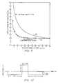
- the PCC is implemented at base band frequencies by sampling the signals in each of the right- and left-half channels 150, 151 after limiting in limiters 61, 62 at a sampling frequency ⁇ s .
- FIG. 9 shows the loss in signal-to-noise ratio as a function of relative sampling rate ⁇ s / ⁇ c ( ⁇ c is the cut-off frequency of the filter) for the case of the RC low-pass input filter, curve 70 (from IEEE Transactions on Information Theory, January 1963, H. Ekre); and the rectangular low-pass input filters, curve 71.
- the mean value of the signal produced by the polarity coincidence correlator 15 is not deterministic.
- the mean value is a function of what is happening in the water environment so that the post-detection filter 20 is desired to be a tracking type filter. It is not possible to remove the mean of PCC 15 as at the output of the SCR 14 by the use of a constant subtracted from the output of the correlator 14. In essence, the post-detection filter 20 is a high pass filter.
- the PCC 15 output there is correlated interference signal produced by the ocean and the noise of the ship carrying the sonar system which provides a variety of "steady-state" correlated interference signals with varying correlation levels. These correlated interferences are dynamically but slowly changing.
- the post-detection filter 20 must track these variations without significantly changing the established PFA.
- the filter must also have a low probability of causing spurious target indications from high SNR targets which are off-axis.
- the filter 64 also should not significantly degrade the output SNR from the detection processor 15.
- the output mean which is a function of range (i.e. a function of own-ship noise correlation and reverberation) was used to evaluate the dynamic response of the post-detection filter 20.
- Another criterion for the design of the filter 20 is that for a high SNR target, beams adjacent to the beam which is directed on the target produce a large negative output which when combined with the impulse response of the filter can cause threshold excesses to the left or right of the real target and also before and after in range.
Landscapes
- Engineering & Computer Science (AREA)
- Physics & Mathematics (AREA)
- Radar, Positioning & Navigation (AREA)
- Remote Sensing (AREA)
- Computer Networks & Wireless Communication (AREA)
- General Physics & Mathematics (AREA)
- Acoustics & Sound (AREA)
- Measurement Of Velocity Or Position Using Acoustic Or Ultrasonic Waves (AREA)
Claims (13)
- Sonarsystem zur Detektierung von Signalen, welche von Objekten reflektiert werden, die durch einen ausgesendeten Schallimpuls angestrahlt werden, mit- einem ersten Schallempfänger (100) und einem zweiten Schallempfänger (200) mit grundlegend unterschiedlichen Eigenschaften zur gleichzeitigen Verarbeitung der reflektierten Signale, wobei der erste und der zweite Empfänger (100,200) Ausgangssignale entsprechend den genannten Objekten bei einer ersten Falschalarmrate und einer zweiten Falschalarmrate an ihren jeweiligen Ausgängen erzeugen, und- Mitteln (40) zum Kombinieren der Ausgänge des ersten Empfängers und des zweiten Empfängers (100,200) zur Erzeugung eines Ausgangssignales, das eine niedrigere Falschalarmrate hat als diejenige, welche durch den ersten und den zweiten Empfänger (100,200) jeweils einzeln erzeugt werden,dadurch gekennzeichnet, daß- der erste Empfänger (100) einen Wiederholungssignal-Segment-Korrelator (14) enthält,- der zweite Empfänger (200) einen Polaritäts-Übereinstimmungs-Korrelator (15) enthält, und- die Kombinationsmittel (40) einen der jeweiligen Ausgänge der Empfänger (100,200) auswählen, um ein Ausgangssignal hervorzubringen, das eine niedrigere Falschalarmrate hat als diejenigen, die von dem ersten und dem zweiten Empfänger (100,200) jeweils einzeln erzeugt werden.
- System nach Anspruch 1, gekennzeichnet durch eine Wandlerreihe (13), erste Strahlformungsmittel (11), die ein Ganzstrahlsignal erzeugen und zwischen die Wandlerreihe (13) und den Wiederholungssignal-Segment-Korrelator (14) geschaltet sind, und zweite Strahlformungsmittel (12), welche Geteiltstrahlsignale erzeugen und zwischen die Wandlerreihe (13) und den Polaritätsübereinstimmungkorrelator (15) geschaltet sind.
- System nach Anspruch 1, dadurch gekennzeichnet, daß es die Entfernung und die Richtung eines Objektes aus einer Folge von ersten und zweiten Signalechos bildet, die von dem Objekt reflektiert werden, das durch eine entsprechende Folge von ersten und zweiten ausgesendeten Sonarsignalen angestrahlt wird, wobei die Folge von Signalechos zu einem Eingang des Wiederholungssignal-Segment-Korrelators (14) und des Polaritätsübereinstimmungskorrelators (15) geführt wird, und daß die Kombinationsmittel einen Detektor (40) enthalten, dessen Eingang mit den jeweiligen Ausgängen des ersten und des zweiten Korrelators (14,15) verbunden ist, ein Entfernungs- und Richtungs-Ausgangssignal erzeugt und auf die Entfernungs- und Richtungs-Signale jedes der Ausgänge des ersten und des zwei-ten Korrelators anspricht, um ein entsprechendes Detektorausgangssignal hervorzubringen, wenn die Entfernungs- und Richtungsinformation des genannten ersten Signalechos von dem ersten und dem zweiten Korrelatorausgang zusammenfallen, wobei der Detektor (40) Mittel (50) enthält, um die Differenz bezüglich Entfernung und Richtung des genannten ersten und zweiten Signalechos zu bestimmen und ein Entfernungs- und Richtungs-Ausgangssignal in Abhängigkeit von den genannten Differenzbestimmungsmitteln (50) zu erzeugen, wenn die Entfernung und die Richtung des ersten Signalechos von einem der Korrelatorausgänge innerhalb einer vorbestimmten Differenz der Entfernung und Richtung des zweiten Signalechos von einem der Korrelatorausgänge liegt.
- System nach Anspruch 3, gekennzeichnet durch- eine Wandleranordnung (13),- einen Ganzstrahl-Strahlformer (11), dessen Ausgang mit dem Eingang des Wiederholungssignal-Segment-Korrelator (14) verbunden ist und mit einem Eingang Verbindung zu den Wandlern der Reihe (13) hat,- einen Geteiltstrahl-Strahlformer (12) mit zwei Ausgängen (150,151), wobei jeder dieser Ausgänge an einen gesonderten Eingang des polaritäts-Übereinstimmungs-Korrelators (15) verbunden ist und ein Eingang des Geteiltstrahl-Strahlformers (12) mit den Wandlern der Reihe (13) Verbindung hat.
- System nach Anspruch 3, dadurch gekennzeichnet, daß der Wiederholungssignal-Segment-Korrelator (14) und der Polaritäts-Übereinstimmungs-Korrelator (15) jeweils eine harte Begrenzung und eine Bandbreitenbegrenzung der Signale an ihren Eingängen vornehmen.
- System nach Anspruch 5, gekennzeichnet durch- eine Mittelwertbeseitiungsschaltung (17,18), die an den Ausgang des Wiederholungssignal-Segment-Korrelators (14) angeschlossen ist,- ein erstes Nachdetektorfilter (19), das an den Ausgang der Mittelwertbeseitigungsschaltung (17,18) angeschlossen ist,- einen Richtungsinterpolator (21), der an den Ausgang des ersten Nachdetektorfilters (19) angeschlossen ist,- eine erste Schwellwertschaltung (23), die an den Ausgang des ersten Richtungsinterpolators (21) angeschlossen ist, wobei der Ausgang der ersten Schwellwertschaltung (23) mit einem ersten Eingang des Detektors (40) Verbindung hat, und- eine an den Ausgang des Detektors (40) angeschlossene Wiedergabeeinrichtung (16).
- System nach Anspruch 1, dadurch gekennzeichnet, daß- Wandlermittel (13) vorgesehen sind, um aufeinanderfolgend akustische Echosignale weiterzugeben, die an den Wiederholungssignal-Segment-Korrelator (14) und an den Polaritäts-Übereinstimmungs-Korrelator (15) angekoppelt sind, und daß- die Kombinationsmittel folgendes enthalten:
einen rechnergestützten Zielobjektdetektor (40), dessen Eingänge mit den Ausgängen der beiden Korrelatoren (14,15) gekoppelt sind, wobei der Detektor (40) auf die Entfernungsinformation und die Richtungsinformation der Ausgangssignale jedes der genannten Ausgänge anspricht, um ein entsprechendes Entfernungs- und Richtungs-Ausgangssignal zu erzeugen, wenn die Entfernung und die Richtung des Korrelatorausgangssignale zusammenfallen, wobei der Detektor (40) Mittel (50) zur Bestimmung der Differenz bezüglich Entfernung und Richtung des ersten und zweiten aufeinanderfolgenden akustischen Pfeif-Echosignales enthält und wobei ein Entfernungs- und Richtungs-Ausgang in Abhängigkeit von den genannten Differenzbestimmungsmitteln (50) erzeugt werden, wenn die Entfernung und die Richtung irgendeines Korrelatorausganges auf ein vorhergehendes Pfeil-Echosignal hin innerhalb einer vorbestimmten Differenz von Entfernung und Richtung von einem Korrelatorausgang auf ein gegenwärtiges Pfeif-Echosignal hin liegt. - System nach Anspruch 7, dadurch gekennzeichnet, daß die Wandlermittel eine Wandlerreihe (13) enthalten und daß ein Ganzstrahl-Strahlformer (11) mit seinem Ausgang mit dem Eingang des Wiederholungssignal-Segment-Korrelators (14) und mit einem Eingang an die Wandler der Reihe (13) gelegt ist, und daß ein Geteiltstrahl-Strahlformer (12) mit zwei Ausgängen vorgesehen ist, die jeweils mit je einem gesonderten Eingang des Polaritäts-Übereinstimmung-Korrelators (15) verbunden sind, während ein Eingang des Geteiltstrahl-Strahlformers (12) mit den Wandlern der Reihe (13) verbunden ist.
- System nach Anspruch 8, dadurch gekennzeichnet, daß der Wiederholungssignal-Segment-Korrelator (14) und der Polaritäts-Übereinstimmungs-Korrelator (15) jeweils an ihren jeweiligen Ausgängen ein harte Begrenzung ung eine Bandbreitenbegrenzung des Signales an ihren Eingängen vornehmen.
- System nach Anspruch 9, dadurch gekennzeichnet, daß der Detektor (40) einen Rechner enthält, in welchem die Ausgangssignale des Wiederholungssignal-Segment-Korrelators (SRC)(14) und des Polaritäts-Übereinstimmung-Korrelators (PCC)(15) verarbeitet werden, wobei der Rechner folgendes enthält:- Mittel zur Übertragung der gegenwärtigen SRC- und PCC-Korrelatorsignale von einem ersten Speicher (41, 42) in einen zweiten Speicher (44,45) als vorausgegangene SRC- und PCC-Ausgangssignale,- Mittel zum Speichern der genannten SRC- und PCC-Korrelatorausgangssignale als gegenwärtige SRC- und PCC-Korrelatorausgangssignale in dem ersten Speicher (41, 42),- Mittel zur Auswahl eines gegenwärtigen PCC-Ausgangssignales aus dem ersten Speicher (41,42),- erste Mittel (46) zum Vergleichen der Entfernung und der Richtung des genannten gegenwärtigen PCC-Ausgangssignales, das aus dem ersten Speicher (41,42) gewählt ist, mit der Entfernung und der Richtung eines gegenwärtigen SRC-Ausgangssignales aus dem ersten Speicher (41,42) zur Feststellung einer Übereinstimmung,- Mittel (48), die auf das Übereinstimmen von Entfernung und Richtung der gegenwärtigen Signale, die verglichen wurden, ansprechen, um eine aktuelle SRC-Liste sämtlicher SRC-Signale zu löschen, welche dieselbe Entfernung und Richtungen innerhalb eines vorbestimmten Richtungssektors in dem ersten Speicher (41,42) haben, und um die Entfernung und Richtung der Übereinstimmung als ein Ausgangssignal zu einer Wiedergabeeinrichtung (16) zu liefern,- zweite Mittel (50), welche auf das Nichtauftreten der genannten Übereinstimmung ansprechen, um die Entfernung und Richtung der genannten ausgewählten gegenwärtigen PCC-Ausgangssignale von dem ersten Speicher (41,42) mit der Entfernung und Richtung der Ausgangssignale bezüglich der vorausgehenden SRC- und PCC-Ausgangssignale des zweiten Speichers (44,45) zu vergleichen, um zu bestimmen, ob die genannten gegenwärtigen und vorausgehenden Ausgangssignale sich innerhalb vorbestimmter Differenzen halten, und- Mittel, die auf die genannten gegenwärtigen und vorausgehenden Ausgangssignale von dem ersten und dem zweiten Speicher (41,42; 44,45) jeweils ansprechen, um die Wiedergabeeinrichtung (16) dazu zuveranlassen, sowohl das genannte gegenwärtige PCC-Ausgangssignal als auch die vorausgehenden SRC- oder PCC-Ausgangssignale anzuzeigen, wenn das genannte gegenwärtige PCC-Ausgangssignal und das vorausgehende SRC-Ausgangssignal oder PCC-Ausgangssignal sich innerhalb der genannten vorbestimmten Differenzen finden, und schließlich- Mittel zur Auswahl und Zuführung eines unterschiedlichen gegenwärtigen PCC-Ausgangssignales und eines gegenwärtigen SRC-Ausgangssignales von dem ersten Speicher (41,42) zu den ersten Vergleichermitteln (46), wenn das genannte gegenwärtige PCC-Ausgangssignal und das vorausgehende SRC-Ausgangssignal oder PCC-Ausgangssignal von dem ersten bzw. zweiten Speicher (41,42; 44,45) nicht innerhalb der genannten bestimmten Differenz liegen.
- System nach Anspruch 9, gekennzeichnet durch- eine Mittelwertbeseitigungsschaltung (17,18), die mit dem Ausgang des Wiederholungssignal-Segment-Korrelators (14) verbunden ist,- ein erstes Nach-Detektor-Filter (19), das mit dem Ausgang der Mittelwertbeseitigungsschaltung (17,18) verbunden ist,- eine erste Schwellwertschaltung (23) die mit dem Ausgang des ersten Nach-Detektor-Filters (19) gekoppelt ist, wobei der Ausgang der ersten Schwellwertschaltung (23) mit einem ersten Eingang des rechnergestützten Zielobjektdetektors (40) verbunden ist,- ein zweites Nach-Detektor-Filter (20), das mit dem Ausgang des Polaritäts-Übereinstimmungs-Korrelators (15) und einem zweiten Eingang des rechnergestutzten Zielobjektdetektor (40) verbunden ist, und- eine Wiedergabeeinrichtung (16), die an den Ausgang des Zielobjektdetektors (40) angeschlossen ist.
- System nach Anspruch 11, gekennzeichnet durch einen ersten und einen zweiten Richtungsinterpolator (21,22), die zwischen den Ausgang des ersten bzw. des zweiten Nach-Detektor-Filters (19,20) und den ersten bzw. zweiten Eingang des rechnergestützten Zielobjektdetektors (40) geschaltet sind.
- System nach Anspruch 7, dadurch gekennzeichent, daß der rechnergestütze Zielobjektdetektor (40) folgendes enthält:- erste Mittel (41,42) zur Speicherung der gegenwärtigen Ausgangspfeifsignale bezüglich Entfernung und Richtung von dem Wiederholungssignal-Segment-Korrelator (SRC) und dem Folaritäts-Übereinstimmung-Korrelator (PCC),- zweite Mittel (44,45), die an den Ausgang der ersten Speichermittel (41,42) angeschlossen sind, zur Speicherung der vorausgehenden SRC- und PCC-Ausgangspfeifsignale bezüglich Entfernung und Richtung,- eine Empfängerassotiationsschaltung (46), die Eingänge von den ersten Speichermitteln (41,42) für die SRC- und PCC-Signale erhält, um eine Entsprechung zwischen den Entfernungen und Richtungen der SRC- und PCC-Ausgangssignale festzustellen,- Mittel (48), die auf die genannte Entsprechung reagieren und mit den ersten Speichermitteln (41,42) verbunden sind, um aus den ersten Speichermitteln (41,42) SRC-Signale zu löschen, welche Richtungen innerhalb eines vorbestimmten Richtungssektors haben und welche die gleiche Entfernung wie die SRC- und PCC-Signale haben, welche die genannte Übereinstimmung aufweisen,- eine Wiedergabeeinrichtung (16), wobei die Empfängerassotiationsschaltung (46) außerdem ein Ausgangssignal einer Entfernung und einer Richtung an die Wiedergabeeinrichtung (16) in Abhängigkeit von einer Übereinstimmung zwischen den genannten SRC- und PCC-Ausgangssignalen bezüglich Entfernung und Richtung liefert, und- Mittel (50) zum Vergleichen der gegenwärtigen SRC- und PCC- Ausgangspfeifsignale aus den ersten Speichermitteln (41,42) mit den vorausgehenden SRC- und PCC-Ausgangspfeifsignalen aus den zweiten Speichermitteln (44,45) zum Feststellen einer Entsprechung zwischen den genannten verglichenen Signalen innerhalb eines vorbestimmten Entfernungs- und Richtungsschrittes und zur Lieferung der genannten verglichenen Signale zu der Wiedergabeeinrichtung (16), wenn die genannte Entsprechung vorhanden ist.
Applications Claiming Priority (2)
| Application Number | Priority Date | Filing Date | Title |
|---|---|---|---|
| US33305 | 1987-04-02 | ||
| US07/033,305 US4831602A (en) | 1987-04-02 | 1987-04-02 | Simultaneous coherent and incoherent processor for sonar signals |
Publications (3)
| Publication Number | Publication Date |
|---|---|
| EP0285325A2 EP0285325A2 (de) | 1988-10-05 |
| EP0285325A3 EP0285325A3 (en) | 1990-05-09 |
| EP0285325B1 true EP0285325B1 (de) | 1994-03-16 |
Family
ID=21869645
Family Applications (1)
| Application Number | Title | Priority Date | Filing Date |
|---|---|---|---|
| EP88302624A Expired - Lifetime EP0285325B1 (de) | 1987-04-02 | 1988-03-24 | Sonarsignalverarbeitungsgerät |
Country Status (7)
| Country | Link |
|---|---|
| US (1) | US4831602A (de) |
| EP (1) | EP0285325B1 (de) |
| JP (1) | JP2656295B2 (de) |
| KR (1) | KR0135612B1 (de) |
| AU (1) | AU601559B2 (de) |
| DE (1) | DE3888377T2 (de) |
| ES (1) | ES2050154T3 (de) |
Families Citing this family (17)
| Publication number | Priority date | Publication date | Assignee | Title |
|---|---|---|---|---|
| US4953145A (en) * | 1988-09-30 | 1990-08-28 | Honeywell Inc. | Active phase quieting target highlight detector |
| US5077702A (en) * | 1990-11-16 | 1991-12-31 | General Electric Company | Doppler consistent hyperbolic frequency modulation |
| IL101077A (en) * | 1991-03-18 | 1995-08-31 | Hydroacoustic Inc | A system for measuring distances using echoes |
| US5212489A (en) * | 1991-03-18 | 1993-05-18 | Hydroacoustics Inc. | Echo ranging system for detecting velocity of targets using composite doppler invariant transmissions |
| US5251185A (en) * | 1992-10-15 | 1993-10-05 | Raytheon Company | Sonar signal processor and display |
| US5568411A (en) * | 1994-07-25 | 1996-10-22 | National Semiconductor Corporation | Method and apparatus for using polarity-coincidence correlators in LMS adaptive filters |
| US5515055A (en) * | 1995-04-03 | 1996-05-07 | Hydroacoustics, Inc. | System for processing returns from a target from transmissions containing repeated signals to detect the doppler velocity of the target |
| US20070159922A1 (en) * | 2001-06-21 | 2007-07-12 | Zimmerman Matthew J | 3-D sonar system |
| WO2004111674A2 (en) * | 2003-06-09 | 2004-12-23 | Brown University | Estimation of background noise and its effect on sonar range estimation |
| KR100682402B1 (ko) * | 2004-08-10 | 2007-02-15 | 국방과학연구소 | 수중센서 어레이 시스템의 신호 검출장치 및 이것을이용한 신호 전달방법 |
| US7266042B1 (en) | 2006-03-31 | 2007-09-04 | The United States Of America As Represented By The Secretary Of The Navy | Multi-stage maximum likelihood target estimator |
| WO2007127271A2 (en) * | 2006-04-24 | 2007-11-08 | Farsounder, Inc. | 3-d sonar system |
| US8589462B2 (en) * | 2008-01-14 | 2013-11-19 | Elmos Semiconductor Ag | Digital optimal filter for periodically alternating signals |
| JP5625771B2 (ja) * | 2010-11-08 | 2014-11-19 | 日本電気株式会社 | 水中目標物検出装置、該検出装置に用いられる目標物検出方法及び目標物検出プログラム |
| US9053349B1 (en) * | 2014-05-08 | 2015-06-09 | Hrl Laboratories, Llc | Digital correlator / FIR filter with tunable bit time using analog summation |
| AU2019355546B2 (en) | 2018-10-04 | 2022-09-22 | Cutsforth, Inc. | System and method for monitoring the status of one or more components of an electrical machine |
| CN115050394B (zh) * | 2022-05-10 | 2025-06-27 | 中国船舶重工集团公司第七一五研究所 | 一种有效降低水声语音通信导引信号虚警概率的检测方法 |
Family Cites Families (13)
| Publication number | Priority date | Publication date | Assignee | Title |
|---|---|---|---|---|
| US31509A (en) * | 1861-02-19 | Photo-lttho | ||
| US3579180A (en) * | 1965-08-06 | 1971-05-18 | Hughes Aircraft Co | Beam interpolating system |
| US3622963A (en) * | 1969-01-29 | 1971-11-23 | Honeywell Inc | Control apparatus |
| US3723952A (en) * | 1970-05-26 | 1973-03-27 | Raytheon Co | Apparatus for differentiating between side lobe and main lobe returns in depth sounding systems |
| US3681747A (en) * | 1970-07-06 | 1972-08-01 | Raytheon Co | Sea bottom slope measuring apparatus |
| US3750152A (en) * | 1972-04-17 | 1973-07-31 | Gen Electric | Pulse-echo phase discriminator using deltic processing |
| USRE31509E (en) | 1974-06-26 | 1984-01-24 | Echo location systems | |
| US4164036A (en) * | 1977-12-07 | 1979-08-07 | Honeywell Inc. | Quadrature correlation phase reversal pulse detector |
| AU6129680A (en) * | 1979-07-30 | 1981-03-03 | Dorian Industries Pty. Ltd. | Method and device for measuring distances |
| FR2465233B1 (fr) * | 1979-09-10 | 1985-11-08 | Plessey Overseas | Appareil de determination de gisement a radar ultrasonore |
| GB2058351B (en) * | 1979-09-10 | 1984-02-01 | Plessey Co Ltd | Sonar systems |
| JPS56100372A (en) * | 1979-12-28 | 1981-08-12 | Ibm | Movinggtarget detector |
| US4404665A (en) * | 1980-10-20 | 1983-09-13 | Raytheon Company | Sea bottom slope compensation apparatus |
-
1987
- 1987-04-02 US US07/033,305 patent/US4831602A/en not_active Expired - Lifetime
-
1988
- 1988-03-22 AU AU13365/88A patent/AU601559B2/en not_active Ceased
- 1988-03-24 EP EP88302624A patent/EP0285325B1/de not_active Expired - Lifetime
- 1988-03-24 ES ES88302624T patent/ES2050154T3/es not_active Expired - Lifetime
- 1988-03-24 DE DE3888377T patent/DE3888377T2/de not_active Expired - Fee Related
- 1988-04-01 JP JP63081138A patent/JP2656295B2/ja not_active Expired - Lifetime
- 1988-04-02 KR KR1019880003753A patent/KR0135612B1/ko not_active Expired - Fee Related
Also Published As
| Publication number | Publication date |
|---|---|
| DE3888377D1 (de) | 1994-04-21 |
| AU1336588A (en) | 1988-10-06 |
| AU601559B2 (en) | 1990-09-13 |
| KR0135612B1 (ko) | 1998-05-15 |
| JP2656295B2 (ja) | 1997-09-24 |
| ES2050154T3 (es) | 1994-05-16 |
| DE3888377T2 (de) | 1994-09-29 |
| JPS63261184A (ja) | 1988-10-27 |
| EP0285325A3 (en) | 1990-05-09 |
| EP0285325A2 (de) | 1988-10-05 |
| US4831602A (en) | 1989-05-16 |
| KR880012995A (ko) | 1988-11-29 |
Similar Documents
| Publication | Publication Date | Title |
|---|---|---|
| EP0285325B1 (de) | Sonarsignalverarbeitungsgerät | |
| Yu et al. | Estimating the delay-Doppler of target echo in a high clutter underwater environment using wideband linear chirp signals: Evaluation of performance with experimental data | |
| US5099456A (en) | Passive locating system | |
| CN111198374A (zh) | 基于时空频联合干扰抑制的多普勒敏感信号动目标水声探测方法 | |
| US5559756A (en) | Acoustic intercept reciever-combined frequency and bearing processor | |
| WO2001094975A1 (en) | System and method for detection and tracking of targets | |
| US20080043574A1 (en) | Sonar system and method providing low probability of impact on marine mammals | |
| CA1203613A (en) | Interference suppression unit for a sonar apparatus | |
| US5949739A (en) | Sonar bearing estimation of extended targets | |
| US5212490A (en) | Echo ranging system for detecting velocity and range of targets using composite doppler invariant-like transmissions with suppression of false targets | |
| US4905206A (en) | Ultrasonic doppler flow meter | |
| AU613527B2 (en) | Active phase quieting target highlight detector | |
| JP2554152B2 (ja) | 移動目標表示ユニット及びレーダー装置 | |
| US5150335A (en) | Frequency interrupt continuous transmit active sonar transmission and signal processing technique | |
| US6654315B1 (en) | Sonar display system and method | |
| AU664802B2 (en) | Echo ranging system | |
| US4225954A (en) | Acoustical deverberator | |
| Kincaid | Optimum Waveforms for Correlation Detection in the Sonar Environment: Noise‐Limited Conditions | |
| Henderson | Wide-band monopulse sonar: Processor performance in the remote profiling application | |
| Mansour et al. | PC-based real-time active sonar simulator | |
| Stergiopoulos et al. | Theory and Implementation of Advanced Signal Processing for Active and Passive Sonar Systems | |
| Foxt et al. | Sonar and Radar Wange-Doppler Processing Using a Cone-Shaped Kernel Time-Frequency Representation | |
| Hendershot et al. | Size and angular location estimates of fish schools using spatial correlation | |
| Mika | Fast envelope correlation for passive ranging. | |
| Carter | Sonar display system and method |
Legal Events
| Date | Code | Title | Description |
|---|---|---|---|
| PUAI | Public reference made under article 153(3) epc to a published international application that has entered the european phase |
Free format text: ORIGINAL CODE: 0009012 |
|
| AK | Designated contracting states |
Kind code of ref document: A2 Designated state(s): DE ES GR IT NL |
|
| PUAL | Search report despatched |
Free format text: ORIGINAL CODE: 0009013 |
|
| AK | Designated contracting states |
Kind code of ref document: A3 Designated state(s): DE ES GR IT NL |
|
| 17P | Request for examination filed |
Effective date: 19900829 |
|
| 17Q | First examination report despatched |
Effective date: 19920914 |
|
| GRAA | (expected) grant |
Free format text: ORIGINAL CODE: 0009210 |
|
| AK | Designated contracting states |
Kind code of ref document: B1 Designated state(s): DE ES GR IT NL |
|
| ITF | It: translation for a ep patent filed | ||
| REF | Corresponds to: |
Ref document number: 3888377 Country of ref document: DE Date of ref document: 19940421 |
|
| REG | Reference to a national code |
Ref country code: ES Ref legal event code: FG2A Ref document number: 2050154 Country of ref document: ES Kind code of ref document: T3 |
|
| REG | Reference to a national code |
Ref country code: GR Ref legal event code: FG4A Free format text: 3011763 |
|
| PLBE | No opposition filed within time limit |
Free format text: ORIGINAL CODE: 0009261 |
|
| STAA | Information on the status of an ep patent application or granted ep patent |
Free format text: STATUS: NO OPPOSITION FILED WITHIN TIME LIMIT |
|
| 26N | No opposition filed | ||
| PGFP | Annual fee paid to national office [announced via postgrant information from national office to epo] |
Ref country code: DE Payment date: 20000302 Year of fee payment: 13 |
|
| PGFP | Annual fee paid to national office [announced via postgrant information from national office to epo] |
Ref country code: NL Payment date: 20000307 Year of fee payment: 13 |
|
| PGFP | Annual fee paid to national office [announced via postgrant information from national office to epo] |
Ref country code: ES Payment date: 20000323 Year of fee payment: 13 |
|
| PGFP | Annual fee paid to national office [announced via postgrant information from national office to epo] |
Ref country code: GR Payment date: 20000331 Year of fee payment: 13 |
|
| PG25 | Lapsed in a contracting state [announced via postgrant information from national office to epo] |
Ref country code: ES Free format text: LAPSE BECAUSE OF NON-PAYMENT OF DUE FEES Effective date: 20010326 |
|
| PG25 | Lapsed in a contracting state [announced via postgrant information from national office to epo] |
Ref country code: GR Free format text: LAPSE BECAUSE OF NON-PAYMENT OF DUE FEES Effective date: 20010331 |
|
| PG25 | Lapsed in a contracting state [announced via postgrant information from national office to epo] |
Ref country code: NL Free format text: LAPSE BECAUSE OF NON-PAYMENT OF DUE FEES Effective date: 20011001 |
|
| NLV4 | Nl: lapsed or anulled due to non-payment of the annual fee |
Effective date: 20011001 |
|
| PG25 | Lapsed in a contracting state [announced via postgrant information from national office to epo] |
Ref country code: DE Free format text: LAPSE BECAUSE OF NON-PAYMENT OF DUE FEES Effective date: 20020101 |
|
| REG | Reference to a national code |
Ref country code: ES Ref legal event code: FD2A Effective date: 20030203 |
|
| PG25 | Lapsed in a contracting state [announced via postgrant information from national office to epo] |
Ref country code: IT Free format text: LAPSE BECAUSE OF NON-PAYMENT OF DUE FEES;WARNING: LAPSES OF ITALIAN PATENTS WITH EFFECTIVE DATE BEFORE 2007 MAY HAVE OCCURRED AT ANY TIME BEFORE 2007. THE CORRECT EFFECTIVE DATE MAY BE DIFFERENT FROM THE ONE RECORDED. Effective date: 20050324 |