EP0285352B1 - Neurale Berechnung durch zeitliche Konzentration - Google Patents
Neurale Berechnung durch zeitliche Konzentration Download PDFInfo
- Publication number
- EP0285352B1 EP0285352B1 EP19880302729 EP88302729A EP0285352B1 EP 0285352 B1 EP0285352 B1 EP 0285352B1 EP 19880302729 EP19880302729 EP 19880302729 EP 88302729 A EP88302729 A EP 88302729A EP 0285352 B1 EP0285352 B1 EP 0285352B1
- Authority
- EP
- European Patent Office
- Prior art keywords
- time
- input
- sequence
- signal
- pattern
- Prior art date
- Legal status (The legal status is an assumption and is not a legal conclusion. Google has not performed a legal analysis and makes no representation as to the accuracy of the status listed.)
- Expired - Lifetime
Links
Images




Classifications
-
- G—PHYSICS
- G10—MUSICAL INSTRUMENTS; ACOUSTICS
- G10L—SPEECH ANALYSIS TECHNIQUES OR SPEECH SYNTHESIS; SPEECH RECOGNITION; SPEECH OR VOICE PROCESSING TECHNIQUES; SPEECH OR AUDIO CODING OR DECODING
- G10L15/00—Speech recognition
- G10L15/08—Speech classification or search
- G10L15/16—Speech classification or search using artificial neural networks
-
- G—PHYSICS
- G10—MUSICAL INSTRUMENTS; ACOUSTICS
- G10L—SPEECH ANALYSIS TECHNIQUES OR SPEECH SYNTHESIS; SPEECH RECOGNITION; SPEECH OR VOICE PROCESSING TECHNIQUES; SPEECH OR AUDIO CODING OR DECODING
- G10L25/00—Speech or voice analysis techniques not restricted to a single one of groups G10L15/00 - G10L21/00
Definitions
- This invention relates to pattern recognition systems.
- Neural networks have been described by J. J. Hopfield in "Neurons With Graded Response Have Collective Computational Properties Like Those of Two-state Neurons"; Proc. Natl. Sci., USA Vol. 81, pp. 3088-3092; and by J. J. Hopfield and D. W. Tank in "'Neural' Computation of Decisions in Optimization Problems", Biological Cybernetics, Vol. 52, 1985 pp. 141-152; as well as in U. S. patent application Serial No. 693,479 filed on behalf of J. J. Hopfield on January 2, 1985, and U.S. patent application Serial No. 795,789 filed on behalf of J. J. Hopfield and D. W. Tank on November 7, 1985.
- a neural network is a highly parallel computational circuit comprising a plurality of amplifiers, with each of the amplifiers feeding back its output signal to itself and all of the other amplifiers or chosen other amplifiers through conductance T ij .
- the T ij conductances (where T ij denotes the conductance between the output of amplifier j and the input of amplifier i) and the associated connections can be thought of as comprising a connection network which has one output signal set and two input signal sets.
- the output signal set is applied to the amplifier inputs, one of the input signal sets is derived from the amplifier outputs, and the other input signal set is responsive to input stimuli applied to the neural network.
- an input interconnection network may be interposed between the input stimuli and the second set of inputs of the feedback network.
- the input interconnection network which comprises a feed-forward arrangement, converts the expected input signals to corresponding signals that drive the feedback network and the amplifiers. There is no time dependence, however, in this interconnection network.
- the arrangement described can be employed to perform many tasks, and we described, by way of example in our 795,789 patent application, its use as an A/D converter. However, not all tasks can be performed with this arrangement alone, and recognition of patterns in time-dependent signals is one such task.
- Recognizing patterns in time-dependent signals is an important task that we perform effortlessly in our everyday life. For example, the tasks of recognizing individual spoken phonemes, isolated spoken words, and words in a continuous stream of speech are rapidly accomplished by a person who understands the language being spoken. Similarly, in a movie, if a person is replaced by a pattern of a few dots representing parts of the body, and the person is moving, people who see only the moving dots can immediately identify the dynamic pattern as "a person moving", in spite of complete inability to recognize a "person” from a stationary pattern of the dots (e.g., a single frame of such a movie).
- the arrangement described permits recognizing some elementary signal patterns. More recently, a temporal associative memory has been described by K. Fukushima (1973) KyberneticVol. 12, pp. 58-63.
- the network functions by mapping the previous states along a spatial gradient using a set of discrete time delays (shift register). At each clock cycle, the pattern of activity projects the network into the next state in the sequence, using connections that code for all known sequential projections in the same way that associative networks code for all known memories.
- the general pattern recognition problem is illustrated by two sequences, in which each letter symbol represents a particular momentary stimulus state, and the time duration of the stimulus states is represented by letter repetitions.
- the first sequence (the sound of the word "series") represents the searched-for stimulus sequence
- the second sequence is the data in which a distorted version of the first sequence is embedded in a continuous stream ("this series sounds").
- the pattern recognition task is to recognize the first sequence in the second data stream.
- Difficulties include (1) where to start the comparison (word-break problem), and (2) given a starting point, different examples of the sequence may be distorted both in time (time warp problem) and in form (missing or extraneous signals).
- An arrangement embodying the invention may comprise a neural network, an input interconnection network, and a plurality of signal modification circuits.
- the arrangement responds to a plurality of input leads which deliver a preselected characteristic stimulus to each associated signal modification unit.
- each signal modification unit develops a plurality of output signals that begin at the time of stimulus application, rise to a peak, and decay thereafter. The mean time delay of each output (time to reach the peak) is different for each of the modification unit output signals.
- the outputs of the signal modification units are applied to the input interconnection network wherein connections are made in accordance with the sequences, or patterns, that are to be recognized, and the output of the interconnection network is applied to the neural network.
- the concept and use of the energy function can be extended to time varying input stimuli.
- the essence of the energy function formulation for time-varying signals is that the circuit's behavior is related to the energy function in such a way that the motion of the circuit, while decreasing E, moves in the direction of detecting the correct input sequence as the information is being fed to the circuit.
- the central geometrical idea in computing with time-varying inputs can be easily visualized using the "space-time" E surface illustrated in FIG. 1.
- FIG. 1 depicts an energy surface of a two-neuron system (two amplifiers in the neural network) with the state of the system being described by the “configuration” axis. There is also a “time” axis and the “E” energy axis in the FIG. 1 depiction.
- the initial energy function of the FIG. 1 system is described by curve 10 and it is characterized by two valleys, at points 11 and 12.
- Valleys 11 and 12 reflect the fact that when an input is applied, the two interconnected amplifiers in the neural network act as a flip-flop which can rest in one of two states (i.e., valley 11 or valley 12).
- valley 11 or valley 12 When an input is applied to the flip-flop in order to set the flip-flop to one of the two states, the energy function changes to emphasize one valley and to de-emphasize the other valley, and the state of the system moves from wherever it was to the emphasized valley. Thus, the flip-flop is set to the desired state.
- the setting input is, in fact, a time varying stimulus that changes the energy function as shown, for example, by the successive curves 15 and 20.
- the changing energy function creates a path of continually decreasing value of energy function E that leads, in FIG. 1, to the deep valley of point 25. That path (assuming the initial state is at point 11) is depicted in FIG. 1 by curve 30.
- Subsequent input signals again change the energy function and move the state of the system from point 25 to the other deep valley of the energy function, at point 35.
- the path traversed from point 25 to point 35 is depicted in FIG. 1 (at least its visible portion) by curve 40.
- the applied input stimuli acting through the time-dependent connections can be viewed as controls for setting or resetting the flip-flop.
- the flip-flop and time-dependent interconnection network can be viewed as a circuit for detecting the appearance of particular stimuli in the input signals. It is with the latter view that a multi-neuron circuit can be used to detect sequences of stimuli in time-varying input signals.
- FIG. 2 includes feature detectors 51-53 which are responsive to signals applied on line 50 and which are tuned to detect particular features in the input signal.
- the output signals of feature detectors 51-53 are each applied to a signal conditioner circuit 55 (the stretched delay means) which develops the aforementioned signals that are used to create the path for the circuit dynamics and concentrate the information in the input signals to the time of sequence detection.
- the output signals of signal conditioners 55 are applied to interconnection network 60, and the output signals of interconnection network 60 are applied to neural network 70.
- the neural network comprises an amplifier network (72) and a feedback network (71).
- the feedback network accepts the output signals of the interconnection network, and the output signals of amplifier network 72 comprise the output signal of the FIG. 2 circuit.
- Feature detectors 51-53 in FIG. 2 form a part of the input signal preparation apparatus, and are highly related to the specific application in connection with which our invention is employed. Indeed, in some applications a single multi-output detector can serve as the means for identifying features of the input signal. For example, if the data stream comprises text that is encoded in some manner, then the task is to detect valid codes. That task can be accomplished with a single, multi-output, feature detector. If, one the other hand, the data stream represents spoken speech, then the task of feature detectors 51-53 may be to identify formants, or phonemes. That task may, perhaps, be best accomplished with a plurality of feature detectors. Most languages, including English, can be described in terms of a fairly small set of distinctive sounds, or phonemes.
- V i and V j are the output voltages of amplifiers i and j, respectively, in amplifier network 72; T ij is the conductance within the feedback network that connects the output of amplifier j to the input of amplifier i; R i is the input impedance of amplifier i; g -1 i (V) is the inverse of the transfer function of amplifier i; and l i is the current input to feedback network 71 (from network 60) leading to the input of amplifier i.
- the energy function of network 70 is changed, as discussed above, through the last term in equation (1).
- Discreteness in the signals domain is reflected in the FIG. 2 circuit by the finite plurality of feature detector outputs, while discreteness in the time domain is embodied in the finite plurality of outputs from signal conditioners 55.
- a searched-for sequence Scan be described by the exemplar stimuli sequence such as
- the f k ( ⁇ ) term relates to the k th output signal of signal conditioner 55, and the coefficient T iXm ;k represents the strength of the connection between the f k ( ⁇ ) signal that is associated with the signal conditioner connected to the feature detector of stimulus X m , and the j th output of interconnection network 60 (which develops the l i signal).
- the f k ( ⁇ ) function defines the stretchable delay of conditioners 55. It is akin to the impulse response of a circuit that, when pulsed (when X m is detected and DX m momentarily goes to 1), an output signal is developed that has a particular shape as a function of time.
- the fk(t) terms thus provide a spreading in time of the momentary pulse, as well as amplitude control of the output.
- each neuron i is "tuned" to a different sequence S i by the organization and delay characteristics of the connections.
- This arrangement is somewhat elementary in the sense that although it is convenient to simply look at neuron j to determine whether sequence j has been detected, there is no reason to make the arrangement this restrictive. Any output vector can be assigned to declare that a particular sequence has been detected, as long as the synaptic connection is appropriately arranged.
- an amplifier network 72 with N amplifiers can accommodate only N sequences, whereas with a less restrictive arrangement a larger number of sequences can be detected. Still, the "grandmother” cell arrangement is quite satisfactory for many applications.
- f k ( ⁇ ) it is realized that one can employ either digital or analog techniques and realizations.
- An analog realization for example, may be attained by employing a chain of simple RC low pass networks separated by buffer amplifiers. With such an implementation, the entire circuit embodying the invention may be created in analog and asynchronous form.
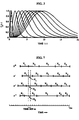
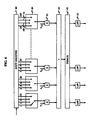
- FIG. 4 depicts one of the FIG. 3 curves
- a low pass filter 83 e.g., a sample and hold circuit
- the difference in the f k ( ⁇ ) function between different k values can be a mere stretching in time, as it is in the family of curves expressed by Equation (4).
- Such a family of curves can be easily realized, then, by a circuit not unlike the one depicted in FIG. 6 where multiplexers 84 and 85 permit time sharing of the bank of multipliers 81.
- multiplexers 84 in FIG. 6 are drawn as if connected to sequential outputs of shift register 80.
- Each of the multiplexers has a number of inputs equal to the number of different f k ( ⁇ ) functions, M, (for example, 10 in FIG. 6 corresponding to the 10 functions drawn in FIG. 3), the length of shift register 80 is KM (240 in FIG. 6), and the clock driving register 80 is adjusted to provide the appropriate maximum time delay.
- multiplexers 84 and 85 scan through their inputs synchronously and in rapid succession, and at each state of the multiplexers a set of products is generated and applied to combining circuit 82. The developed sums are distributed to appropriate low pass filters 83 in synchronism with the multiplexers.
- f k ( ⁇ ) functions were chosen for this disclosure because they are reasonable functions which have the desired characteristics. They may be good choices when no information is available concerning the statistical behavior of the input signal. A better choice is possible, however, when information about the nature of the likely time distortions is available.
- a typical known exemplar sequence S might look as sketched in FIG. 7.
- Typical time-wrap distortions ⁇ ', ⁇ ", ⁇ "' differ from S in that individual stimuli X i in the sequence differ in duration.
- sequence ⁇ signal consisting of the stimuli sequence (X i at time bin 1,X j at time bin 2,..., X k at time bin m), be received in the data stream. If we consider only mean correlations per time bin, then the conditional probability distribution for the sequence can be factored as the product of m conditional probability distributions of finding the various symbols in the time bins, as If the input to each of the j sequence recognition units in the network due to the detection of stimulus X ; at an earliertime bin m is proportional to In[P m (X i S J )], the relative inputs to the recognition units will be proportional to the probability that the sequence of stimuli just received is a distortion of its exemplar sequence.
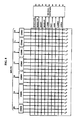
- FIG. 9 depicts a simple speech detection circuit in conformance with the principles of our invention. Because of its simplified nature the FIG. 9 circuit is speaker-dependent. For some commercial applications speaker dependence is an asset (e.g., voice actuated access to one's home).
- the feature detector output signals are obtained from a single feature detector 54 (as compared to the plurality of elements in FIG. 2), and that feature detector comprises an AGC circuit 541 responsive to input signals of line 50, bandpass filter/de- tector elements 542 responsive to AGC 541, a detector/differentiator 543 responsive to AGC 541, and a linear programming circuit 544.
- Bandpass filters 542 are arranged in FIG. 9 to detect the presence of energy in selected narrow bands between 200 Hz to 3.5 kHz.
- each of the filters is a narrow band filter (with a Q value of approximately 5), with the center frequencies of the bandpass filters distributed linearly on a logarithmic frequency scale.
- the outputs of the bandpass filters are rectified and integrated to provide an output for each element 542 that is a measure of the power within the detected band that is present in the input signal.
- broadband energy is detected in element 543 and differentiated to provide a measure of dE/dt in the input signal.
- Linear programming circuit 544 comprises linear amplifiers 546 interposed between each input and output of circuit 544 and, in addition, the output signals of amplifiers 546 are combined with a bias signal and applied to a constraint neuron (amplifier 545).
- Amplifier 545 creates an inhibiting signal that is applied to the input of all amplifiers 546 whenever the sum of the output signals of amplifiers 546 exceeds the bias signal.
- the linear programming circuit provides a set of W i which maximize the sum subject to the constraint When the signals are strong, this maximization selects the largest channel, inhibiting the others.
- the outputs of elements 544 comprise the outputs of feature detector 54, and those outputs are fed to signal conditioner units (stretchable delay means) 55.
- Units 55 of FIG. 9 comprise ten four-pole bessel filters, each with a different ⁇ . As in FIG. 2, the outputs of units 55 are fed to interconnection network 60, and interconnection network 60 applies its output signals to neural network 70.
Landscapes
- Engineering & Computer Science (AREA)
- Physics & Mathematics (AREA)
- Health & Medical Sciences (AREA)
- Audiology, Speech & Language Pathology (AREA)
- Human Computer Interaction (AREA)
- Computational Linguistics (AREA)
- Acoustics & Sound (AREA)
- Multimedia (AREA)
- Signal Processing (AREA)
- Artificial Intelligence (AREA)
- Evolutionary Computation (AREA)
- Image Analysis (AREA)
- Image Processing (AREA)
Claims (8)
Applications Claiming Priority (2)
| Application Number | Priority Date | Filing Date | Title |
|---|---|---|---|
| US3394287A | 1987-04-03 | 1987-04-03 | |
| US33942 | 1987-04-03 |
Publications (3)
| Publication Number | Publication Date |
|---|---|
| EP0285352A2 EP0285352A2 (de) | 1988-10-05 |
| EP0285352A3 EP0285352A3 (de) | 1991-01-09 |
| EP0285352B1 true EP0285352B1 (de) | 1995-03-15 |
Family
ID=21873353
Family Applications (1)
| Application Number | Title | Priority Date | Filing Date |
|---|---|---|---|
| EP19880302729 Expired - Lifetime EP0285352B1 (de) | 1987-04-03 | 1988-03-28 | Neurale Berechnung durch zeitliche Konzentration |
Country Status (5)
| Country | Link |
|---|---|
| EP (1) | EP0285352B1 (de) |
| JP (1) | JPH07113839B2 (de) |
| CA (1) | CA1303222C (de) |
| DE (1) | DE3853308T2 (de) |
| MX (1) | MX169483B (de) |
Families Citing this family (4)
| Publication number | Priority date | Publication date | Assignee | Title |
|---|---|---|---|---|
| CA2003183C (en) * | 1988-11-17 | 1996-06-18 | Shingo Nishimura | Speaker recognition system |
| GB8908205D0 (en) * | 1989-04-12 | 1989-05-24 | Smiths Industries Plc | Speech recognition apparatus and methods |
| JPH0823762B2 (ja) * | 1989-06-06 | 1996-03-06 | 日産自動車株式会社 | 自動車用空調装置 |
| GB9103349D0 (en) * | 1991-02-18 | 1991-04-03 | King Reginald A | Artificial neural network systems |
-
1988
- 1988-03-28 EP EP19880302729 patent/EP0285352B1/de not_active Expired - Lifetime
- 1988-03-28 DE DE19883853308 patent/DE3853308T2/de not_active Expired - Fee Related
- 1988-03-29 CA CA 562764 patent/CA1303222C/en not_active Expired
- 1988-03-30 MX MX1094388A patent/MX169483B/es unknown
- 1988-03-31 JP JP7667588A patent/JPH07113839B2/ja not_active Expired - Fee Related
Also Published As
| Publication number | Publication date |
|---|---|
| JPS63262774A (ja) | 1988-10-31 |
| DE3853308D1 (de) | 1995-04-20 |
| EP0285352A3 (de) | 1991-01-09 |
| MX169483B (es) | 1993-07-07 |
| CA1303222C (en) | 1992-06-09 |
| EP0285352A2 (de) | 1988-10-05 |
| JPH07113839B2 (ja) | 1995-12-06 |
| DE3853308T2 (de) | 1995-08-24 |
Similar Documents
| Publication | Publication Date | Title |
|---|---|---|
| US4937872A (en) | Neural computation by time concentration | |
| US5790754A (en) | Speech recognition apparatus for consumer electronic applications | |
| Biem et al. | An application of discriminative feature extraction to filter-bank-based speech recognition | |
| Unnikrishnan et al. | Connected-digit speaker-dependent speech recognition using a neural network | |
| Ahmad et al. | Recurrent neural network with backpropagation through time for speech recognition | |
| US5566270A (en) | Speaker independent isolated word recognition system using neural networks | |
| Shahamiri et al. | A multi-views multi-learners approach towards dysarthric speech recognition using multi-nets artificial neural networks | |
| KR100306848B1 (ko) | 신경회로망을 이용한 선택적 주의집중 방법 | |
| Pan et al. | An event-based cochlear filter temporal encoding scheme for speech signals | |
| EP0285352A2 (de) | Neurale Berechnung durch zeitliche Konzentration | |
| Selouani et al. | Automatic birdsong recognition based on autoregressive time-delay neural networks | |
| Ryeu et al. | Chaotic recurrent neural networks and their application to speech recognition | |
| Sailor et al. | Unsupervised Representation Learning Using Convolutional Restricted Boltzmann Machine for Spoof Speech Detection. | |
| JPS6129518B2 (de) | ||
| Lee et al. | Recurrent neural networks for speech modeling and speech recognition | |
| Wang et al. | Speaker verification and identification using gamma neural networks | |
| Agrawal et al. | Robust raw waveform speech recognition using relevance weighted representations | |
| Greco et al. | A recurrent time-delay neural network for improved phoneme recognition. | |
| Chakraborty et al. | Speech recognition of isolated words using a new speech database in sylheti | |
| KR100211113B1 (ko) | 카오스 순환신경회로망을 이용한 학습방법 및 음성인식방법 | |
| Jou et al. | Mandarin syllables recognition based on one class one net neural network with modified selective update algorithm | |
| White et al. | New strategies for improving speech enhancement | |
| Rouat et al. | Variable frame rate hierarchical analysis for robust speech recognition | |
| GB1603927A (en) | Continuous speech recognition method | |
| Nijhawan et al. | A comparative study of two different neural models for speaker recognition systems |
Legal Events
| Date | Code | Title | Description |
|---|---|---|---|
| PUAI | Public reference made under article 153(3) epc to a published international application that has entered the european phase |
Free format text: ORIGINAL CODE: 0009012 |
|
| AK | Designated contracting states |
Kind code of ref document: A2 Designated state(s): DE FR GB IT |
|
| PUAL | Search report despatched |
Free format text: ORIGINAL CODE: 0009013 |
|
| AK | Designated contracting states |
Kind code of ref document: A3 Designated state(s): DE FR GB IT |
|
| 17P | Request for examination filed |
Effective date: 19910701 |
|
| RAP3 | Party data changed (applicant data changed or rights of an application transferred) |
Owner name: AT&T CORP. |
|
| 17Q | First examination report despatched |
Effective date: 19940513 |
|
| GRAA | (expected) grant |
Free format text: ORIGINAL CODE: 0009210 |
|
| AK | Designated contracting states |
Kind code of ref document: B1 Designated state(s): DE FR GB IT |
|
| ITF | It: translation for a ep patent filed | ||
| ET | Fr: translation filed | ||
| REF | Corresponds to: |
Ref document number: 3853308 Country of ref document: DE Date of ref document: 19950420 |
|
| PLBE | No opposition filed within time limit |
Free format text: ORIGINAL CODE: 0009261 |
|
| STAA | Information on the status of an ep patent application or granted ep patent |
Free format text: STATUS: NO OPPOSITION FILED WITHIN TIME LIMIT |
|
| 26N | No opposition filed | ||
| REG | Reference to a national code |
Ref country code: FR Ref legal event code: TP |
|
| REG | Reference to a national code |
Ref country code: GB Ref legal event code: 732E |
|
| REG | Reference to a national code |
Ref country code: GB Ref legal event code: IF02 |
|
| PGFP | Annual fee paid to national office [announced via postgrant information from national office to epo] |
Ref country code: GB Payment date: 20021231 Year of fee payment: 16 |
|
| PGFP | Annual fee paid to national office [announced via postgrant information from national office to epo] |
Ref country code: FR Payment date: 20030129 Year of fee payment: 16 |
|
| PGFP | Annual fee paid to national office [announced via postgrant information from national office to epo] |
Ref country code: DE Payment date: 20030310 Year of fee payment: 16 |
|
| PG25 | Lapsed in a contracting state [announced via postgrant information from national office to epo] |
Ref country code: GB Free format text: LAPSE BECAUSE OF NON-PAYMENT OF DUE FEES Effective date: 20040328 |
|
| PG25 | Lapsed in a contracting state [announced via postgrant information from national office to epo] |
Ref country code: DE Free format text: LAPSE BECAUSE OF NON-PAYMENT OF DUE FEES Effective date: 20041001 |
|
| GBPC | Gb: european patent ceased through non-payment of renewal fee |
Effective date: 20040328 |
|
| PG25 | Lapsed in a contracting state [announced via postgrant information from national office to epo] |
Ref country code: FR Free format text: LAPSE BECAUSE OF NON-PAYMENT OF DUE FEES Effective date: 20041130 |
|
| REG | Reference to a national code |
Ref country code: FR Ref legal event code: ST |
|
| PG25 | Lapsed in a contracting state [announced via postgrant information from national office to epo] |
Ref country code: IT Free format text: LAPSE BECAUSE OF NON-PAYMENT OF DUE FEES;WARNING: LAPSES OF ITALIAN PATENTS WITH EFFECTIVE DATE BEFORE 2007 MAY HAVE OCCURRED AT ANY TIME BEFORE 2007. THE CORRECT EFFECTIVE DATE MAY BE DIFFERENT FROM THE ONE RECORDED. Effective date: 20050328 |