EP0285355B1 - Drahtförmige Bindeelemente - Google Patents
Drahtförmige Bindeelemente Download PDFInfo
- Publication number
- EP0285355B1 EP0285355B1 EP88302738A EP88302738A EP0285355B1 EP 0285355 B1 EP0285355 B1 EP 0285355B1 EP 88302738 A EP88302738 A EP 88302738A EP 88302738 A EP88302738 A EP 88302738A EP 0285355 B1 EP0285355 B1 EP 0285355B1
- Authority
- EP
- European Patent Office
- Prior art keywords
- indentation
- wire
- prongs
- binding element
- comb
- Prior art date
- Legal status (The legal status is an assumption and is not a legal conclusion. Google has not performed a legal analysis and makes no representation as to the accuracy of the status listed.)
- Expired - Lifetime
Links
- 238000007373 indentation Methods 0.000 claims abstract description 32
- 238000005452 bending Methods 0.000 claims abstract description 5
- 238000000034 method Methods 0.000 description 4
- 238000005520 cutting process Methods 0.000 description 3
- 239000011295 pitch Substances 0.000 description 3
- 238000005260 corrosion Methods 0.000 description 2
- 230000007797 corrosion Effects 0.000 description 2
- 239000004677 Nylon Substances 0.000 description 1
- 238000006243 chemical reaction Methods 0.000 description 1
- 230000006835 compression Effects 0.000 description 1
- 238000007906 compression Methods 0.000 description 1
- 238000004519 manufacturing process Methods 0.000 description 1
- 239000000463 material Substances 0.000 description 1
- 239000002184 metal Substances 0.000 description 1
- 229920001778 nylon Polymers 0.000 description 1
Images
Classifications
-
- B—PERFORMING OPERATIONS; TRANSPORTING
- B42—BOOKBINDING; ALBUMS; FILES; SPECIAL PRINTED MATTER
- B42B—PERMANENTLY ATTACHING TOGETHER SHEETS, QUIRES OR SIGNATURES OR PERMANENTLY ATTACHING OBJECTS THERETO
- B42B5/00—Permanently attaching together sheets, quires or signatures otherwise than by stitching
- B42B5/08—Permanently attaching together sheets, quires or signatures otherwise than by stitching by finger, claw or ring-like elements passing through the sheets, quires or signatures
- B42B5/10—Permanently attaching together sheets, quires or signatures otherwise than by stitching by finger, claw or ring-like elements passing through the sheets, quires or signatures the elements being of castellated or comb-like form
Definitions
- This invention relates to wire binding elements for perforated sheets and to the manufacture of such elements.
- a known method of binding perforated sheets uses binding elements which are lengths of wire bent so as to form curved prongs on which the sheets are impaled.
- the element is provided, at the time of the impaling operation, in the form of a tube having a longitudinal slot in its wall and the final stage in the binding process is to close the slot by bringing the closed end of the prongs into their open ends.
- Such elements are generally manufactured by firstly converting a length of wire to the so-called 'zig-zag' form, hereinafter referred to as a strip of zig-zagged wire of the kind set forth, in which the wire assumes the shape of a flat comb of indefinate length the prongs of which are 'closed' at their tips and 'open' at their bases or roots which are connected to their neighbours by aligned lengths of wire forming the stock or spine of the comb so that the pitch of the prongs corresponds to the pitch of the perforations in the sheet to be bound.
- a long length of such flat zigzag material is then brought to the slotted tube form, hereinafter referred to as a slotted tubular form as set forth herein, by suitable bending of the prongs.
- Such binding elements have been provided with a "nick” or indentation on the outer surface of the prongs midway between the tip and root thereof. As is described in U.S. Patent 2130318, this is to facilitate the closing of the element in the final bending operation by dictating the fulcrum of the bend.
- the prongs have a tendency to bend, not at the 'nick' as expected, but rather, at a point a short distance away from the 'nick' around the curved prongs. This occurs especially in binding elements of larger pitches and wire diameters.
- the 'nick' is provided on the tension side of the element, it has a tendency to tear apart when the element is closed and become aesthetically unsightly especially when the element is formed from nylon coated wire.
- a further problem which has been found is that the 'nick' can provide an ingress point for corrosion.
- a binding element for perforated sheets in accordance with the present invention comprises a length of wire bent so as to form curved prongs on which the sheets may be impaled, the wire being in the shape of a flat comb, the prongs of which are closed at their tips and opened at their bases or roots which are connected to their neighbours by aligned lengths of wire forming the stock or the spine of the comb, the strip being designed to be converted to a slotted tube by suitable bending of the prongs wherein that part of each prong which is midway between its tip and root is provided with an indentation, characterised in that the indentation is provided on the inner surface of the prong.
- the indentation may be produced either by a forming operation or by a cutting operation.
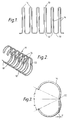
- the strip 10 shown in Figure 1 is comb like, having prongs 14 closed at their tips 16 and open at their roots 18 where they are connected by lengths of wire 20.
- the strip 10 When the strip 10 has been converted to the slotted tubular form, it is in the condition illustrated in Figure 2 with the prongs 14 curved so that perforated sheets can be impaled. That operation having been performed, the binding is completed by bringing the tips 16 of the prongs into their roots or open ends 18.
- the binding element is provided with an indentation 22 on the concave side of each prong 14 midway between its root and tip as shown in Figure 3.
- the indentation dictates the position of the bend on closing the element thus ensuring that the final configuration of the element is a full round circle.
- the prongs had a tendency to bend, not around the position defined by the indentation but around the weakest points on the curved wire, a short distance away from the indentation around the curved prongs.
- the position of the indentation is such that the indentation is not readily seen and that on closing there will be no tendency for it to tear open; rather it will close up. Therefore, the indentation is extremely unlikely to provide an ingress point for corrosion.
- the sides of the indentation make angles ⁇ and ⁇ with axis x-x of the binding element. These angles are preferably equal to each other so that the indentation is symmetrical about the axis. Angle ⁇ (or ⁇ ) is preferably between 45° about 55°.
- the depth of the indentation, dimension P on Figure 3 will obviously depend on the diameter of the wire from which the binding element is made.
- the maximum value of P is preferably about 40% of the diameter of the wire.
- the conversion of a strip zigzagged wire to the slotted tube condition may be effected by feeding the wire over an anvil in a step-by-step fashion and, while the strip is held stationary, clamping it so that the tips and roots of the prongs overhang the anvil.
- the overhanging portion of each prong is then struck with two or more hammers to cause it to conform to a shape determined by the anvil i.e. to the slotted tube configuration.
- the indentation may be produced in the last stage of such an operation by providing a projection on the anvil and a corresponding depression on the clamp. The indentation will then be formed as the binding element leaves the apparatus.
- a cutting operation could be employed instead i.e. to remove rather than to displace metal.
- a forming or cutting tool can be positioned before the slotted tube forming means so that the indentation is produced while the wire is still in the zigzagged condition. This has the advantage of aiding centralisation of the strip prior to the tube forming operation.
- the tools used to produce the indentations should preferably be adjustable so that the depth of the indentation may be varied.
- the indentation may be cut or formed in different shapes but is preferably always symmetrical about the mirror axis of the prongs.
Landscapes
- Engineering & Computer Science (AREA)
- Textile Engineering (AREA)
- Sheet Holders (AREA)
- Package Frames And Binding Bands (AREA)
- Wire Bonding (AREA)
- Superconductors And Manufacturing Methods Therefor (AREA)
- Materials For Medical Uses (AREA)
- Laminated Bodies (AREA)
- Internal Circuitry In Semiconductor Integrated Circuit Devices (AREA)
- Liquid Crystal (AREA)
- Surgical Instruments (AREA)
Claims (4)
- Bindeelement für perforierte Blätter, umfassend eine Drahtlänge, die so gebogen ist, daß sie gekrümmte Zacken bildet, auf denen die Blätter aufgespießt werden können, wobei der Draht die Gestalt eines flachen Kammes aufweist, dessen Zacken an ihren Spitzen geschlossen an ihrer Basis bzw. ihren Wurzeln offen sind, die mit ihren Nachbarn durch ausgerichtete Drahtlängen verbunden sind, die den Stamm oder das Rückgrat des Kammes bildet, wobei der Streifen so ausgebildet ist, daß er durch geeignetes Biegen der Zacken in eine geschlitzte Röhre umgewandelt wird, worin der Teil einer jeden Zacke, der sich auf halbem Weg zwischen der Spitze und der Wurzel befindet, mit einer Einkerbung versehen ist, dadurch gekennzeichnet, daß die Einkerbung (22) an der inneren Oberfläche der Zacke (14) vorgesehen ist.
- Bindeelement nach Anspruch 1, worin die Seiten der Einkerbung (22) einen gleichen Winkel zur Hauptquerachse des Bindeelements (10) aufweisen, sodaß die Einkerbung (22) um ihre Achse symmetrisch ist.
- Bindelement nach Anspruch 2, worin der Winkel um etwa 45° und 50° liegt.
- Bindeelement nach einem der vorhergehenden Ansprüche, worin die Tiefe der Einkerbung (22) etwa 40 % des Durchmessers des Drahtes beträgt.
Priority Applications (1)
| Application Number | Priority Date | Filing Date | Title |
|---|---|---|---|
| AT88302738T ATE81996T1 (de) | 1987-04-02 | 1988-03-28 | Drahtfoermige bindeelemente. |
Applications Claiming Priority (2)
| Application Number | Priority Date | Filing Date | Title |
|---|---|---|---|
| GB8707843 | 1987-04-02 | ||
| GB8707843A GB2202792B (en) | 1987-04-02 | 1987-04-02 | Improvements in and relating to wire binding elements |
Publications (3)
| Publication Number | Publication Date |
|---|---|
| EP0285355A2 EP0285355A2 (de) | 1988-10-05 |
| EP0285355A3 EP0285355A3 (en) | 1990-01-24 |
| EP0285355B1 true EP0285355B1 (de) | 1992-11-04 |
Family
ID=10615083
Family Applications (1)
| Application Number | Title | Priority Date | Filing Date |
|---|---|---|---|
| EP88302738A Expired - Lifetime EP0285355B1 (de) | 1987-04-02 | 1988-03-28 | Drahtförmige Bindeelemente |
Country Status (11)
| Country | Link |
|---|---|
| US (1) | US4832370A (de) |
| EP (1) | EP0285355B1 (de) |
| AT (1) | ATE81996T1 (de) |
| DE (1) | DE3875643T2 (de) |
| DK (1) | DK167964B1 (de) |
| ES (1) | ES2036675T3 (de) |
| GB (1) | GB2202792B (de) |
| GR (1) | GR3006812T3 (de) |
| HK (1) | HK1492A (de) |
| IE (1) | IE61189B1 (de) |
| SG (1) | SG91191G (de) |
Cited By (2)
| Publication number | Priority date | Publication date | Assignee | Title |
|---|---|---|---|---|
| EP1216843A2 (de) | 2000-12-06 | 2002-06-26 | Bertelsmann Kalender & Promotion Service GmbH | Wandkalender mit einem lösbaren Befestigungselement |
| DE102009011699A1 (de) | 2008-10-14 | 2010-04-15 | Kugler-Womako Gmbh | Binden von aufeinander gestapelten Flachteilen |
Families Citing this family (16)
| Publication number | Priority date | Publication date | Assignee | Title |
|---|---|---|---|---|
| US6126353A (en) * | 1997-09-13 | 2000-10-03 | Howard Mullin | Curled finger hinge binder |
| US6113298A (en) * | 1998-04-15 | 2000-09-05 | Miro; Ruth Julia | Paper ring |
| AU2433501A (en) * | 1999-12-17 | 2001-06-25 | General Binding Corporation | Binding apparatus |
| AU2002217778A1 (en) | 2000-11-22 | 2002-06-03 | General Binding Corporation | Plurality of binding elements for automated processes |
| US20020106265A1 (en) * | 2000-11-29 | 2002-08-08 | Mario Litsche | Binding apparatus and method |
| US20040240967A1 (en) * | 2001-08-29 | 2004-12-02 | Phillip Crudo | Binding elements for binding a wide range of thicknesses of stacks of sheets |
| US20040018041A1 (en) * | 2001-11-20 | 2004-01-29 | Samuel Amdahl | Plurality of binding elements for automated processes |
| US6406208B1 (en) * | 2001-11-28 | 2002-06-18 | Yu-Hsien Hsu | File binder structure |
| US20030031502A1 (en) * | 2002-08-30 | 2003-02-13 | Rothschild Wayne H. | Binding element stacking structure |
| US6764100B1 (en) | 2003-06-11 | 2004-07-20 | Ruth Julia Miro | Stationery organizer |
| WO2005018949A2 (en) | 2003-08-11 | 2005-03-03 | General Binding Corporation | Binding elements and methods of forming binding elements |
| BE1015676A3 (nl) * | 2003-09-08 | 2005-07-05 | Unibind Cyprus Ltd | Inbindelement. |
| US20050238414A1 (en) * | 2004-04-16 | 2005-10-27 | General Binding Corporation | Disposable clip for coupling binding elements and combination of binding elements with disposable coupling clip |
| CA2573096A1 (en) * | 2004-07-12 | 2006-02-16 | General Binding Corporation | Binding element and plurality of binding elements particularly suited for automated processes |
| US8123448B2 (en) * | 2005-08-16 | 2012-02-28 | General Binding Corporation | Apparatus and methods for automatically binding a stack of sheets with a nonspiral binding element |
| USD620977S1 (en) | 2006-08-04 | 2010-08-03 | General Binding Corporation | Binding element |
Family Cites Families (3)
| Publication number | Priority date | Publication date | Assignee | Title |
|---|---|---|---|---|
| US2130318A (en) * | 1936-12-12 | 1938-09-13 | Trussell Mfg Co | Wire forming machine and method |
| US3333411A (en) * | 1964-08-07 | 1967-08-01 | Republic Fastener Products Cor | Apparatus for forming a hog ring |
| FR1542471A (fr) * | 1966-12-06 | 1968-10-18 | Machine à relier automatique |
-
1987
- 1987-04-02 GB GB8707843A patent/GB2202792B/en not_active Expired - Lifetime
-
1988
- 1988-03-28 DE DE8888302738T patent/DE3875643T2/de not_active Expired - Lifetime
- 1988-03-28 AT AT88302738T patent/ATE81996T1/de active
- 1988-03-28 EP EP88302738A patent/EP0285355B1/de not_active Expired - Lifetime
- 1988-03-28 ES ES198888302738T patent/ES2036675T3/es not_active Expired - Lifetime
- 1988-03-29 US US07/175,038 patent/US4832370A/en not_active Expired - Lifetime
- 1988-03-29 IE IE93788A patent/IE61189B1/en not_active IP Right Cessation
- 1988-03-30 DK DK177188A patent/DK167964B1/da not_active IP Right Cessation
-
1991
- 1991-10-31 SG SG911/91A patent/SG91191G/en unknown
-
1992
- 1992-01-02 HK HK14/92A patent/HK1492A/xx not_active IP Right Cessation
-
1993
- 1993-01-14 GR GR930400067T patent/GR3006812T3/el unknown
Cited By (3)
| Publication number | Priority date | Publication date | Assignee | Title |
|---|---|---|---|---|
| EP1216843A2 (de) | 2000-12-06 | 2002-06-26 | Bertelsmann Kalender & Promotion Service GmbH | Wandkalender mit einem lösbaren Befestigungselement |
| DE102009011699A1 (de) | 2008-10-14 | 2010-04-15 | Kugler-Womako Gmbh | Binden von aufeinander gestapelten Flachteilen |
| EP2177366A2 (de) | 2008-10-14 | 2010-04-21 | Kugler-Womako GmbH | Binden von aufeinander gestapelten Flachteilen |
Also Published As
| Publication number | Publication date |
|---|---|
| GB2202792B (en) | 1991-05-08 |
| US4832370A (en) | 1989-05-23 |
| DE3875643T2 (de) | 1993-04-01 |
| GB2202792A (en) | 1988-10-05 |
| GB8707843D0 (en) | 1987-05-07 |
| DK177188D0 (da) | 1988-03-30 |
| EP0285355A2 (de) | 1988-10-05 |
| ES2036675T3 (es) | 1993-06-01 |
| SG91191G (en) | 1991-12-13 |
| IE61189B1 (en) | 1994-10-19 |
| DE3875643D1 (de) | 1992-12-10 |
| HK1492A (en) | 1992-01-10 |
| GR3006812T3 (de) | 1993-06-30 |
| DK167964B1 (da) | 1994-01-10 |
| EP0285355A3 (en) | 1990-01-24 |
| DK177188A (da) | 1988-10-03 |
| IE880937L (en) | 1988-10-02 |
| ATE81996T1 (de) | 1992-11-15 |
Similar Documents
| Publication | Publication Date | Title |
|---|---|---|
| EP0285355B1 (de) | Drahtförmige Bindeelemente | |
| US4983176A (en) | Deformable plastic surgical clip | |
| NO165288B (no) | Silisiumpulver og fremgangsmaate for fremstilling av silisiumpulver. | |
| EP0668837B1 (de) | Elastische klammeranordnung | |
| WO1994025362A1 (en) | Improved sheet metal clip | |
| US5682994A (en) | Collated clip assembly | |
| US4080714A (en) | Flexible polishing drum segment and method of making and mounting same | |
| US5314064A (en) | Sheet metal clip | |
| US5878880A (en) | Collated clip assembly | |
| EP0983453B1 (de) | Spiralförmige produkte | |
| US3151443A (en) | Method of making strip stake-on terminals and article | |
| DE1665422A1 (de) | Verfahren und Vorrichtung zum Verbinden von Draehten | |
| GB2259273A (en) | ðPPARATUS FOR WIRE BINDING PERFORATED SHEETS | |
| DE202021106427U1 (de) | Spangenteil für eine Nagelkorrekturspange | |
| EP0611636A1 (de) | Einrichtung zum Schneiden eines Produktes in Scheiben sowie Verfahren zur Herstellung einer solchen Einrichtung | |
| DE235630C (de) | ||
| DE2300993C2 (de) | Zangenartig ausgebildete Vorrichtung zum Verschließen von Verpackungshüllen | |
| US6493907B2 (en) | Wire terminal fastener and method | |
| AU730840B2 (en) | Wire crimping tool | |
| SK98198A3 (en) | Manufacturing elastic rail clamps | |
| DE1210411B (de) | Heftzange zum Ausbilden von ringfoermigen Heft-klammern | |
| DE2336413B2 (de) | Verfahren zum Herstellen einer elektrischen Verbindung zwischen einem elektrischen Leiter und einem elektrischen Verbinder sowie hierzu zu verwendender elektrischer Verbinder | |
| DE20014074U1 (de) | Klemmhalter | |
| DE143267A (de) |
Legal Events
| Date | Code | Title | Description |
|---|---|---|---|
| PUAI | Public reference made under article 153(3) epc to a published international application that has entered the european phase |
Free format text: ORIGINAL CODE: 0009012 |
|
| AK | Designated contracting states |
Kind code of ref document: A2 Designated state(s): AT BE CH DE ES FR GB GR IT LI LU NL SE |
|
| PUAL | Search report despatched |
Free format text: ORIGINAL CODE: 0009013 |
|
| AK | Designated contracting states |
Kind code of ref document: A3 Designated state(s): AT BE CH DE ES FR GB GR IT LI LU NL SE |
|
| 17P | Request for examination filed |
Effective date: 19900305 |
|
| 17Q | First examination report despatched |
Effective date: 19910805 |
|
| RBV | Designated contracting states (corrected) |
Designated state(s): AT BE CH DE ES FR GR IT LI LU NL SE |
|
| GRAA | (expected) grant |
Free format text: ORIGINAL CODE: 0009210 |
|
| AK | Designated contracting states |
Kind code of ref document: B1 Designated state(s): AT BE CH DE ES FR GR IT LI LU NL SE |
|
| REF | Corresponds to: |
Ref document number: 81996 Country of ref document: AT Date of ref document: 19921115 Kind code of ref document: T |
|
| REF | Corresponds to: |
Ref document number: 3875643 Country of ref document: DE Date of ref document: 19921210 |
|
| ET | Fr: translation filed | ||
| ITF | It: translation for a ep patent filed | ||
| PG25 | Lapsed in a contracting state [announced via postgrant information from national office to epo] |
Ref country code: LU Free format text: LAPSE BECAUSE OF NON-PAYMENT OF DUE FEES Effective date: 19930331 |
|
| REG | Reference to a national code |
Ref country code: GR Ref legal event code: FG4A Free format text: 3006812 |
|
| REG | Reference to a national code |
Ref country code: ES Ref legal event code: FG2A Ref document number: 2036675 Country of ref document: ES Kind code of ref document: T3 |
|
| PLBE | No opposition filed within time limit |
Free format text: ORIGINAL CODE: 0009261 |
|
| STAA | Information on the status of an ep patent application or granted ep patent |
Free format text: STATUS: NO OPPOSITION FILED WITHIN TIME LIMIT |
|
| 26N | No opposition filed | ||
| EAL | Se: european patent in force in sweden |
Ref document number: 88302738.5 |
|
| PGFP | Annual fee paid to national office [announced via postgrant information from national office to epo] |
Ref country code: AT Payment date: 20000313 Year of fee payment: 13 |
|
| PGFP | Annual fee paid to national office [announced via postgrant information from national office to epo] |
Ref country code: GR Payment date: 20000331 Year of fee payment: 13 |
|
| PG25 | Lapsed in a contracting state [announced via postgrant information from national office to epo] |
Ref country code: AT Free format text: LAPSE BECAUSE OF NON-PAYMENT OF DUE FEES Effective date: 20010328 |
|
| PG25 | Lapsed in a contracting state [announced via postgrant information from national office to epo] |
Ref country code: GR Free format text: LAPSE BECAUSE OF NON-PAYMENT OF DUE FEES Effective date: 20010331 |
|
| PGFP | Annual fee paid to national office [announced via postgrant information from national office to epo] |
Ref country code: BE Payment date: 20020527 Year of fee payment: 15 |
|
| PG25 | Lapsed in a contracting state [announced via postgrant information from national office to epo] |
Ref country code: BE Free format text: LAPSE BECAUSE OF NON-PAYMENT OF DUE FEES Effective date: 20030331 |
|
| BERE | Be: lapsed |
Owner name: JAMES *BURN INTERNATIONAL LTD Effective date: 20030331 |
|
| PGFP | Annual fee paid to national office [announced via postgrant information from national office to epo] |
Ref country code: IT Payment date: 20060331 Year of fee payment: 19 |
|
| PGFP | Annual fee paid to national office [announced via postgrant information from national office to epo] |
Ref country code: NL Payment date: 20070327 Year of fee payment: 20 |
|
| PGFP | Annual fee paid to national office [announced via postgrant information from national office to epo] |
Ref country code: CH Payment date: 20070328 Year of fee payment: 20 Ref country code: SE Payment date: 20070328 Year of fee payment: 20 |
|
| PGFP | Annual fee paid to national office [announced via postgrant information from national office to epo] |
Ref country code: DE Payment date: 20070329 Year of fee payment: 20 |
|
| PGFP | Annual fee paid to national office [announced via postgrant information from national office to epo] |
Ref country code: ES Payment date: 20070330 Year of fee payment: 20 |
|
| REG | Reference to a national code |
Ref country code: CH Ref legal event code: PFA Owner name: JAMES BURN INTERNATIONAL LIMITED Free format text: JAMES BURN INTERNATIONAL LIMITED#DOUGLAS ROAD#ESHER/SURREY (GB) -TRANSFER TO- JAMES BURN INTERNATIONAL LIMITED#DOUGLAS ROAD#ESHER/SURREY (GB) |
|
| PG25 | Lapsed in a contracting state [announced via postgrant information from national office to epo] |
Ref country code: NL Free format text: LAPSE BECAUSE OF EXPIRATION OF PROTECTION Effective date: 20080328 |
|
| PGFP | Annual fee paid to national office [announced via postgrant information from national office to epo] |
Ref country code: FR Payment date: 20070327 Year of fee payment: 20 |
|
| REG | Reference to a national code |
Ref country code: CH Ref legal event code: PL |
|
| EUG | Se: european patent has lapsed | ||
| NLV7 | Nl: ceased due to reaching the maximum lifetime of a patent |
Effective date: 20080328 |
|
| REG | Reference to a national code |
Ref country code: ES Ref legal event code: FD2A Effective date: 20080329 |
|
| PG25 | Lapsed in a contracting state [announced via postgrant information from national office to epo] |
Ref country code: ES Free format text: LAPSE BECAUSE OF EXPIRATION OF PROTECTION Effective date: 20080329 |
|
| PG25 | Lapsed in a contracting state [announced via postgrant information from national office to epo] |
Ref country code: IT Free format text: LAPSE BECAUSE OF NON-PAYMENT OF DUE FEES Effective date: 20070328 |