EP0285363B1 - Soupapes rotatives - Google Patents
Soupapes rotatives Download PDFInfo
- Publication number
- EP0285363B1 EP0285363B1 EP88302766A EP88302766A EP0285363B1 EP 0285363 B1 EP0285363 B1 EP 0285363B1 EP 88302766 A EP88302766 A EP 88302766A EP 88302766 A EP88302766 A EP 88302766A EP 0285363 B1 EP0285363 B1 EP 0285363B1
- Authority
- EP
- European Patent Office
- Prior art keywords
- rotor
- valve rotor
- shaft
- port
- valve
- Prior art date
- Legal status (The legal status is an assumption and is not a legal conclusion. Google has not performed a legal analysis and makes no representation as to the accuracy of the status listed.)
- Expired - Lifetime
Links
- 230000015572 biosynthetic process Effects 0.000 claims description 5
- 238000005755 formation reaction Methods 0.000 claims description 5
- 238000002485 combustion reaction Methods 0.000 description 4
- 230000001133 acceleration Effects 0.000 description 1
- 230000006835 compression Effects 0.000 description 1
- 238000007906 compression Methods 0.000 description 1
- 238000001816 cooling Methods 0.000 description 1
- 238000007789 sealing Methods 0.000 description 1
Images
Classifications
-
- F—MECHANICAL ENGINEERING; LIGHTING; HEATING; WEAPONS; BLASTING
- F01—MACHINES OR ENGINES IN GENERAL; ENGINE PLANTS IN GENERAL; STEAM ENGINES
- F01L—CYCLICALLY OPERATING VALVES FOR MACHINES OR ENGINES
- F01L7/00—Rotary or oscillatory slide valve-gear or valve arrangements
- F01L7/08—Rotary or oscillatory slide valve-gear or valve arrangements with conically or frusto-conically shaped valves
-
- F—MECHANICAL ENGINEERING; LIGHTING; HEATING; WEAPONS; BLASTING
- F01—MACHINES OR ENGINES IN GENERAL; ENGINE PLANTS IN GENERAL; STEAM ENGINES
- F01L—CYCLICALLY OPERATING VALVES FOR MACHINES OR ENGINES
- F01L7/00—Rotary or oscillatory slide valve-gear or valve arrangements
- F01L7/06—Rotary or oscillatory slide valve-gear or valve arrangements with disc type valves
Definitions
- the present invention relates to a cylinder head with rotary valve suitable for an internal combustion engine, such as known from GB-A-559830 or GB-A-691275.
- a cylinder head comprises a rotary valve including a valve rotor having an annular discontinuity, the valve being mounted on a shaft for rotation relative to a port so that as it rotates, the discontinuity will open and close the port, drive means being provided to rotate the valve rotor, said drive means including means to reduce the speed of the valve rotor when the port is closed, the port being surrounded by a seating area and means being provided to move the valve rotor so that it engages the seating area and closes the port, when the speed of the valve rotor is reduced and move the valve rotor away from the seating area when the speed of the valve rotor is increased, characterised in that the valve rotor is mounted on the shaft by inter-engaging screw threaded formations, the screw threads being arranged such that rotation of the shaft, when driven, will unscrew the screw threads, means being provided to limit rotation of the valve rotor relative to the shaft.
- the speed of the valve rotor is reduced until it is stationary or near stationary when the port is closed, so that wear between the seating area and the valve rotor will be minimised.
- This may be achieved as disclosed in; British Patent Application No. 8806519 (Publication No. 2203796), in which the drive is transmitted by means of a gear train, the drive gear having teeth over only a portion of its periphery, so that it will only mesh with and drive the driven gear which is connected to the valve rotor over a portion of each revolution of the drive gear, interlock means being provided to keep the driven gear and valve rotor stationary when out of mesh with the drive gear; or European Patent Application No. 88306849.6 (Publication No. 0306141) in which a linkage mechanism is used to provide a varying speed drive which is reduced to almost stationary while the port is closed.
- the change in momentum of the valve rotor as it slows down and speeds up is used to move the valve rotor into engagement with the seating area or away from the seating area respectively.
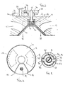
- a rotary valve mechanism for an internal combustion engine comprises a conical valve rotor 10 which is mounted for rotation in a conical cylinder head 11, on a shaft 12.
- the shaft 12 is mounted through a ball bearing 13 by which it is located axially while the valve rotor 10 is rotatably mounted in a recess 19 in the cylinder head 11, on roller bearing 14.
- the conical rotor 10 overlies an exhaust port 15 and an inlet port 16 in the cylinder head 11.
- a segment 17 is removed from the rotor 10 so that as it rotates it will open and close the ports 15 and 16.
- the exhaust and inlet ports 15 and 16 are positioned so that there is a space 18 therebetween which is greater than the segment 17 removed from the disc 10.
- An ignition device 19 is located through the cylinder head 11 in the portion thereof defined by space 18.
- a driven gear 20 is secured to shaft 12 on the outside of the cylinder head 11.
- the gear 20 meshes with the gear 21 which is mounted on a drive shaft 22 by which it is driven by the engine.
- the gear 21 is provided with teeth 24 around only part of its periphery, said teeth 24 meshing with teeth 25 on gear 20.
- the number of teeth 24 on gear 21 is equal to the number of teeth 25 on gear 20, so that for one revolution of gear 21 the gear 20 and rotor 10 will also rotate by one revolution.
- Drive is however interrupted when teeth 24 on gear 21 move out of mesh with teeth 25 on gear 20, over the portion 26 of the periphery of gear 21 which is without teeth.
- a flange formation 27 on gear 20 overlies the periphery of gear 21.
- An arcuate track 28 is provided on the flange formation 27 and a pin 29 mounted on gear 21 engages in this track 28 to prevent rotation of gear 20 and rotor 10, when the teeth 24 and 25 of gears 21 and 20 respectively, are out of mesh.
- the track 28 may be provided with lead in and exit portions which will, respectively, decelerate and accelerate the gear 20 and rotor 10, as described in British Patent Application No. 8806519.
- the shaft 12 is connected to the rotor 10 by means of a multi-start helical thread 30 which engages in a correspondingly threaded recessed portion 31 of the rotor 10.
- the thread 30 is such that rotation of the shaft 12 when driven by the gear train 20, 21 will unscrew the thread.
- Rotation of the rotor 10 relative to the shaft 12 is restricted to a few degrees, by means of a key 32 which is mounted on the shaft 12 and engages in a pair of diametric slots 33 in the upper face of the recessed portion 31 of rotor 10, as illustrated in detail in Figure 3.
- a light torsion of spring 35 acts between the shaft 12 and rotor 10 to bias the rotor 10 in the direction of rotation of shaft 12, when driven.
- the above embodiment thus provides a rotary valve mechanism in which the valve rotor is driven intermittently, the rotor being seated against the cylinder head to seal the ports when stationary and being lifted away from the cylinder head when rotating.
- the valve mechanism consequently offers all the advantages of a rotary valve mechanism while providing positive seating which will produce sealing of the ports equivalent to that of poppet valves. Engagement of the valve rotor against the cylinder head will also assist in cooling of the rotor and help avoid pre-ignition problems.
- valve rotors described above are in the form of a cone or disc with a single aperture, cones or discs with one or more apertures may be used.
Landscapes
- Engineering & Computer Science (AREA)
- Mechanical Engineering (AREA)
- General Engineering & Computer Science (AREA)
- Valve-Gear Or Valve Arrangements (AREA)
- Gear-Shifting Mechanisms (AREA)
- Electrically Driven Valve-Operating Means (AREA)
- Valve Device For Special Equipments (AREA)
- Lubrication Of Internal Combustion Engines (AREA)
Claims (5)
- Culasse, comprenant une soupape rotative constituée d'un rotor formant soupape (10) présentant une discontinuité annulaire (17), le rotor (10) étant monté sur un arbre (12) pour tourner par rapport à une lumière (15; 16) de telle sorte que, tandis qu'il tourne, la discontinuité (17) ouvre et ferme la lumière (15; 16), des moyens d'entraînement étant prévus pour faire tourner le rotor (10), ces moyens d'entraînement (20, 21) comprenant des moyens (24, 25) pour réduire la vitesse du rotor (10) lorsque la lumière (15; 16) est fermée, la lumière (15; 16) étant entourée d'une zone d'appui, et des moyens (30, 31) étant prévus pour déplacer le rotor (10) de façon qu'il vienne en appui contre la zone d'appui et ferme la lumière (15; 16) lorsque la vitesse du rotor est réduite, et pour éloigner le rotor (10) de la zone d'appui lorsque la vitesse du rotor (10) est augmentée, caractérisée en ce que le rotor (10) est monté sur l'arbre (12) par l'intermédiaire de filetages (30, 31) en engagement mutuel, les filetages étant disposés de façon que la rotation de l'arbre (12), lorsqu'il est entraîné, dévisse les filetages l'un par rapport à l'autre, et des moyens (32, 33) étant prévus pour limiter la rotation du rotor (10) par rapport à l'arbre (12).
- Culasse selon la revendication 1, caractérisée en ce que les filetages (30, 31) sont des filetages à pas multiple.
- Culasse selon la revendication 1 ou 2, caractérisée en ce qu'une clavette (32) est fixée sur l'arbre (12) et, afin de limiter la rotation entre le rotor (10) et l'arbre (12), s'engage dans une encoche (33) du rotor (10), encoche qui s'étend dans le plan de rotation.
- Culasse selon l'une quelconque des revendications 1 à 3, caractérisée en ce que le rotor (10) est contraint élastiquement par rapport à l'arbre (12) dans le sens de rotation de ce dernier lorsqu'il est entraîné.
- Culasse selon l'une quelconque des revendications 1 à 4, caractérisé en ce que des moyens formant palier (13) sont prévus pour retenir axialement l'arbre (12), tandis que le rotor (10) est monté libre en déplacement axial.
Priority Applications (1)
| Application Number | Priority Date | Filing Date | Title |
|---|---|---|---|
| AT88302766T ATE70893T1 (de) | 1987-04-03 | 1988-03-29 | Drehventile. |
Applications Claiming Priority (2)
| Application Number | Priority Date | Filing Date | Title |
|---|---|---|---|
| GB8708037 | 1987-04-03 | ||
| GB878708037A GB8708037D0 (en) | 1987-04-03 | 1987-04-03 | Rotary valves |
Publications (3)
| Publication Number | Publication Date |
|---|---|
| EP0285363A2 EP0285363A2 (fr) | 1988-10-05 |
| EP0285363A3 EP0285363A3 (en) | 1989-02-08 |
| EP0285363B1 true EP0285363B1 (fr) | 1991-12-27 |
Family
ID=10615204
Family Applications (1)
| Application Number | Title | Priority Date | Filing Date |
|---|---|---|---|
| EP88302766A Expired - Lifetime EP0285363B1 (fr) | 1987-04-03 | 1988-03-29 | Soupapes rotatives |
Country Status (5)
| Country | Link |
|---|---|
| US (1) | US4838220A (fr) |
| EP (1) | EP0285363B1 (fr) |
| AT (1) | ATE70893T1 (fr) |
| DE (1) | DE3867106D1 (fr) |
| GB (2) | GB8708037D0 (fr) |
Cited By (4)
| Publication number | Priority date | Publication date | Assignee | Title |
|---|---|---|---|---|
| DE102007018433A1 (de) | 2007-04-19 | 2008-10-30 | ThyssenKrupp Metalúrgica Campo Limpo Ltda. | Einlass- und Auslassventilanordnung für eine Verbrennungskraftmaschine |
| DE102012100957A1 (de) | 2012-02-06 | 2013-08-08 | Voestalpine Bwg Gmbh & Co. Kg | Gleisabschnitt für eine Schiene sowie Verfahren zur Erhöhung der elastischen Lagerung |
| DE102012100947A1 (de) | 2012-02-06 | 2013-08-08 | Voestalpine Bwg Gmbh & Co. Kg | Gleisabschnitt für eine Schiene sowie Verfahren zur Erhöhung der elastischen Lagerung |
| WO2013117325A1 (fr) | 2012-02-06 | 2013-08-15 | Voestalpine Bwg Gmbh & Co. Kg | Tronçon de voie pour un rail ainsi que procédé pour améliorer le montage élastique |
Families Citing this family (14)
| Publication number | Priority date | Publication date | Assignee | Title |
|---|---|---|---|---|
| FR2621956A1 (fr) * | 1987-10-16 | 1989-04-21 | Pellerin Jacques | Moteur a combustion interne, a distribution rotative |
| ES2060473B1 (es) * | 1991-05-17 | 1996-11-16 | Dodas Ramon Verdaguer | Motor de combustion interna perfeccionado. |
| US5257601A (en) * | 1993-02-01 | 1993-11-02 | Coffin David F | Adjustable rotary valve assembly for a combustion engine |
| US5967108A (en) | 1996-09-11 | 1999-10-19 | Kutlucinar; Iskender | Rotary valve system |
| US5931134A (en) * | 1997-05-05 | 1999-08-03 | Devik International, Inc. | Internal combustion engine with improved combustion |
| IT1292223B1 (it) * | 1997-05-07 | 1999-01-29 | Giorgio Enrico Falck | Motore a combustione interna provvisto di distribuzione a fodero rotante |
| FR2776704A1 (fr) * | 1998-03-27 | 1999-10-01 | Daniel Drecq | Ensemble comportant un clapet associe a au moins un conduit et moteur thermique equipe de cet ensemble |
| KR100461451B1 (ko) * | 2002-05-14 | 2004-12-14 | 현대자동차주식회사 | 회전식 흡배기밸브장치 |
| US7481189B2 (en) * | 2005-03-09 | 2009-01-27 | Zajac Optimum Output Motors, Inc. | Internal combustion engine and method |
| CZ19452U1 (cs) * | 2006-08-09 | 2009-03-23 | Cekan@Jozef | Ctyrtaktní spalovací motor s rotacním segmentem v rozvodovém mechanismu |
| CH704346B1 (de) * | 2007-02-05 | 2012-07-13 | Imtmedical Ag | Steuerventil für Beatmungsgeräte. |
| IT1393762B1 (it) * | 2008-12-15 | 2012-05-08 | Burgio Di Aragona | Dispositivo per il comando di rotazione intermittente di una valvola di aspirazione e scarico per motori a combustione interna. |
| DE102011010137B4 (de) * | 2011-02-03 | 2014-02-13 | Willi Rehwald | Mechanismen zur Steuerung des Gaswechsels bei Viertakt Verbrennungsmotoren |
| US12345182B2 (en) * | 2019-06-03 | 2025-07-01 | Steve Burkholder | Plate valve four stoke head |
Family Cites Families (17)
| Publication number | Priority date | Publication date | Assignee | Title |
|---|---|---|---|---|
| FR15749E (fr) * | 1912-09-09 | Societe Des Etablissements Malicet Et Blin | Procédé de commande en rotation d'un mobile assujetti à glisser le long d'une paroi guide fixe et dispositifs le réalisant | |
| GB253213A (fr) * | ||||
| FR15916E (fr) * | 1911-03-08 | 1912-10-19 | Societe Des Etablissements Malicet Et Blin | Procédé de commande en rotation d'un mobile assujetti à glisser le long d'une paroi guide fixe et dispositifs le réalisant |
| GB158269A (en) * | 1920-01-21 | 1921-11-17 | Frederick Ridley Dennison | Improvements in or relating to rotary valves |
| US1799759A (en) * | 1927-03-14 | 1931-04-07 | Mcdowell George | Valve for internal-combustion engines |
| GB559830A (en) * | 1943-01-26 | 1944-03-07 | Edward Ambrose Mellors | Improvements relating to valve mechanisms for internal combustion engines |
| US2457206A (en) * | 1945-03-16 | 1948-12-28 | Bert G Carlson | Rotary valve for internalcombustion engines |
| GB691275A (en) * | 1949-12-05 | 1953-05-06 | Ercole Colombo | Improvements in or relating to rotary valve internal combustion piston engines |
| GB687298A (en) * | 1950-07-05 | 1953-02-11 | Kaye S Rotaprint Agency Ltd | Improvements in and relating to sheet feeding means for printing or duplicating machines |
| GB725088A (en) * | 1953-07-31 | 1955-03-02 | Gleason Works | Improvements relating to intermittent mechanical motions |
| GB899724A (en) * | 1958-11-11 | 1962-06-27 | Hisakichi Ichinose | Improvements in or relating to screen printing machines |
| GB900594A (en) * | 1959-01-20 | 1962-07-11 | Graphic Technology Ltd | Improved means for providing intermittent rotary motion |
| US3274901A (en) * | 1964-09-28 | 1966-09-27 | Oscar A Yost | Oscillating port valve |
| GB1162053A (en) * | 1966-08-31 | 1969-08-20 | Omega Brandt & Freres Sa Louis | Device for Displaying a Sequence of Numbers |
| IT1136826B (it) * | 1980-04-23 | 1986-09-03 | Sulzer Ag | Disposizione per il lavaggio e la carica dei cilindri di un motore endotermico a due tempi |
| US4418658A (en) * | 1980-07-07 | 1983-12-06 | Diross James | Engine valve |
| GB2127482B (en) * | 1982-09-21 | 1986-08-13 | Herbert Ball | Internal combustion engine with an oscillating conical valve |
-
1987
- 1987-04-03 GB GB878708037A patent/GB8708037D0/en active Pending
-
1988
- 1988-03-18 GB GB8806519A patent/GB2203796B/en not_active Expired - Lifetime
- 1988-03-29 EP EP88302766A patent/EP0285363B1/fr not_active Expired - Lifetime
- 1988-03-29 AT AT88302766T patent/ATE70893T1/de active
- 1988-03-29 DE DE8888302766T patent/DE3867106D1/de not_active Expired - Lifetime
- 1988-04-01 US US07/176,633 patent/US4838220A/en not_active Expired - Fee Related
Cited By (4)
| Publication number | Priority date | Publication date | Assignee | Title |
|---|---|---|---|---|
| DE102007018433A1 (de) | 2007-04-19 | 2008-10-30 | ThyssenKrupp Metalúrgica Campo Limpo Ltda. | Einlass- und Auslassventilanordnung für eine Verbrennungskraftmaschine |
| DE102012100957A1 (de) | 2012-02-06 | 2013-08-08 | Voestalpine Bwg Gmbh & Co. Kg | Gleisabschnitt für eine Schiene sowie Verfahren zur Erhöhung der elastischen Lagerung |
| DE102012100947A1 (de) | 2012-02-06 | 2013-08-08 | Voestalpine Bwg Gmbh & Co. Kg | Gleisabschnitt für eine Schiene sowie Verfahren zur Erhöhung der elastischen Lagerung |
| WO2013117325A1 (fr) | 2012-02-06 | 2013-08-15 | Voestalpine Bwg Gmbh & Co. Kg | Tronçon de voie pour un rail ainsi que procédé pour améliorer le montage élastique |
Also Published As
| Publication number | Publication date |
|---|---|
| GB8708037D0 (en) | 1987-05-07 |
| DE3867106D1 (de) | 1992-02-06 |
| ATE70893T1 (de) | 1992-01-15 |
| GB2203796A (en) | 1988-10-26 |
| GB8806519D0 (en) | 1988-04-20 |
| GB2203796B (en) | 1991-09-25 |
| US4838220A (en) | 1989-06-13 |
| EP0285363A3 (en) | 1989-02-08 |
| EP0285363A2 (fr) | 1988-10-05 |
Similar Documents
| Publication | Publication Date | Title |
|---|---|---|
| US4838220A (en) | Rotary valves | |
| EP0292185B1 (fr) | Mécanismes à came | |
| CN106285814B (zh) | 一种可变气门正时和可变气门升程的装置 | |
| US20200182331A1 (en) | Gear transmission device | |
| US4570439A (en) | Exhaust control system for 2-cycle engines | |
| EP0279826B1 (fr) | Arbre a cames differentiel | |
| JPH04105906U (ja) | 内燃機関のバルブタイミング制御装置 | |
| JPH0960509A (ja) | 可変バルブタイミング装置 | |
| EP0306141A2 (fr) | Entraînement rotatif | |
| JP2828361B2 (ja) | バルブタイミング調整装置 | |
| US4545338A (en) | Cam shaft timing control device | |
| JPH0325610B2 (fr) | ||
| JP2022548561A (ja) | カムシャフトのバルブの位相を変更する装置を備えた内燃エンジン | |
| JPH0211809A (ja) | 弁開閉時期制御装置 | |
| JPH04148023A (ja) | 自動車用エンジンの吸気制御装置 | |
| JPS6196112A (ja) | 4サイクルエンジンのバルブタイミング可変装置 | |
| JPH0213716Y2 (fr) | ||
| JPH0311363Y2 (fr) | ||
| KR20020054774A (ko) | 베인형 가변 밸브 타이밍 장치 | |
| JP6925572B2 (ja) | バルブタイミング調整装置 | |
| JP2895708B2 (ja) | 弁開閉時期制御装置 | |
| EP0668435B1 (fr) | Dispositif de distribution pour moteurs à combustion interne | |
| JPS6141977Y2 (fr) | ||
| WO1995012750A1 (fr) | Dispositif de regulation de course pour l'admission commandee par soupape en disque dans un moteur deux temps | |
| JPH0583303U (ja) | 内燃機関の弁開閉時期制御装置 |
Legal Events
| Date | Code | Title | Description |
|---|---|---|---|
| PUAI | Public reference made under article 153(3) epc to a published international application that has entered the european phase |
Free format text: ORIGINAL CODE: 0009012 |
|
| AK | Designated contracting states |
Kind code of ref document: A2 Designated state(s): AT BE CH DE ES FR GB GR IT LI LU NL SE |
|
| PUAL | Search report despatched |
Free format text: ORIGINAL CODE: 0009013 |
|
| AK | Designated contracting states |
Kind code of ref document: A3 Designated state(s): AT BE CH DE ES FR GB GR IT LI LU NL SE |
|
| 17P | Request for examination filed |
Effective date: 19890306 |
|
| 17Q | First examination report despatched |
Effective date: 19900419 |
|
| GRAA | (expected) grant |
Free format text: ORIGINAL CODE: 0009210 |
|
| AK | Designated contracting states |
Kind code of ref document: B1 Designated state(s): AT BE CH DE ES FR GB GR IT LI LU NL SE |
|
| PG25 | Lapsed in a contracting state [announced via postgrant information from national office to epo] |
Ref country code: NL Effective date: 19911227 Ref country code: LI Effective date: 19911227 Ref country code: GR Free format text: LAPSE BECAUSE OF FAILURE TO SUBMIT A TRANSLATION OF THE DESCRIPTION OR TO PAY THE FEE WITHIN THE PRESCRIBED TIME-LIMIT Effective date: 19911227 Ref country code: ES Free format text: THE PATENT HAS BEEN ANNULLED BY A DECISION OF A NATIONAL AUTHORITY Effective date: 19911227 Ref country code: CH Effective date: 19911227 Ref country code: BE Effective date: 19911227 Ref country code: AT Effective date: 19911227 |
|
| REF | Corresponds to: |
Ref document number: 70893 Country of ref document: AT Date of ref document: 19920115 Kind code of ref document: T |
|
| REF | Corresponds to: |
Ref document number: 3867106 Country of ref document: DE Date of ref document: 19920206 |
|
| PGFP | Annual fee paid to national office [announced via postgrant information from national office to epo] |
Ref country code: FR Payment date: 19920210 Year of fee payment: 5 |
|
| PGFP | Annual fee paid to national office [announced via postgrant information from national office to epo] |
Ref country code: SE Payment date: 19920217 Year of fee payment: 5 Ref country code: GB Payment date: 19920217 Year of fee payment: 5 |
|
| PGFP | Annual fee paid to national office [announced via postgrant information from national office to epo] |
Ref country code: DE Payment date: 19920219 Year of fee payment: 5 |
|
| ITF | It: translation for a ep patent filed | ||
| ET | Fr: translation filed | ||
| PG25 | Lapsed in a contracting state [announced via postgrant information from national office to epo] |
Ref country code: LU Free format text: LAPSE BECAUSE OF NON-PAYMENT OF DUE FEES Effective date: 19920331 |
|
| REG | Reference to a national code |
Ref country code: CH Ref legal event code: PL |
|
| NLV1 | Nl: lapsed or annulled due to failure to fulfill the requirements of art. 29p and 29m of the patents act | ||
| PLBE | No opposition filed within time limit |
Free format text: ORIGINAL CODE: 0009261 |
|
| STAA | Information on the status of an ep patent application or granted ep patent |
Free format text: STATUS: NO OPPOSITION FILED WITHIN TIME LIMIT |
|
| 26N | No opposition filed | ||
| PG25 | Lapsed in a contracting state [announced via postgrant information from national office to epo] |
Ref country code: GB Effective date: 19930329 |
|
| PG25 | Lapsed in a contracting state [announced via postgrant information from national office to epo] |
Ref country code: SE Effective date: 19930330 |
|
| GBPC | Gb: european patent ceased through non-payment of renewal fee |
Effective date: 19930329 |
|
| PG25 | Lapsed in a contracting state [announced via postgrant information from national office to epo] |
Ref country code: FR Effective date: 19931130 |
|
| PG25 | Lapsed in a contracting state [announced via postgrant information from national office to epo] |
Ref country code: DE Effective date: 19931201 |
|
| REG | Reference to a national code |
Ref country code: FR Ref legal event code: ST |
|
| EUG | Se: european patent has lapsed |
Ref document number: 88302766.6 Effective date: 19931008 |
|
| PG25 | Lapsed in a contracting state [announced via postgrant information from national office to epo] |
Ref country code: IT Free format text: LAPSE BECAUSE OF NON-PAYMENT OF DUE FEES;WARNING: LAPSES OF ITALIAN PATENTS WITH EFFECTIVE DATE BEFORE 2007 MAY HAVE OCCURRED AT ANY TIME BEFORE 2007. THE CORRECT EFFECTIVE DATE MAY BE DIFFERENT FROM THE ONE RECORDED. Effective date: 20050329 |