EP0285418A2 - Dispositif pour la pose de bagues linguales et buccales - Google Patents
Dispositif pour la pose de bagues linguales et buccales Download PDFInfo
- Publication number
- EP0285418A2 EP0285418A2 EP88302886A EP88302886A EP0285418A2 EP 0285418 A2 EP0285418 A2 EP 0285418A2 EP 88302886 A EP88302886 A EP 88302886A EP 88302886 A EP88302886 A EP 88302886A EP 0285418 A2 EP0285418 A2 EP 0285418A2
- Authority
- EP
- European Patent Office
- Prior art keywords
- tooth
- model
- guide
- bracket
- orienting
- Prior art date
- Legal status (The legal status is an assumption and is not a legal conclusion. Google has not performed a legal analysis and makes no representation as to the accuracy of the status listed.)
- Granted
Links
Images



Classifications
-
- A—HUMAN NECESSITIES
- A61—MEDICAL OR VETERINARY SCIENCE; HYGIENE
- A61C—DENTISTRY; APPARATUS OR METHODS FOR ORAL OR DENTAL HYGIENE
- A61C7/00—Orthodontics, i.e. obtaining or maintaining the desired position of teeth, e.g. by straightening, evening, regulating, separating, or by correcting malocclusions
- A61C7/12—Brackets; Arch wires; Combinations thereof; Accessories therefor
- A61C7/14—Brackets; Fixing brackets to teeth
- A61C7/146—Positioning or placement of brackets; Tools therefor
Definitions
- This invention relates to apparatus for precisely establishing archwire slot positions on the labial surfaces of the maloccluded teeth of a dental model.
- the apparatus provides for direct bonding of orthodontic brackets to the labial surfaces of the teeth of the model and also provides for translation of the spatial orientation of an imaginary labial archwire slot to appropriate positions relative to the lingual surfaces of the teeth.
- the apparatus also provides for accurate positioning of orthodontic brackets relative to the lingual surfaces for temporary attachment thereof in readiness for mounting in conventional transfer trays, for indirect bonding of the brackets to the teeth of the patient.
- Bracket placement on the lingual surfaces of a patient's teeth for "straight wire” orthodontics is much more difficult than on the buccal surfaces of the teeth because it is the buccal surfaces of the teeth that are to be aligned to form an anatomically correct dental arch. While there are variations in buccal anatomy, the attachment of the brackets directly to the surfaces to be aligned negates most of the variations and produces excellent results with minimal archwire bending. Ease of manipulation to achieve a quality finished orthodontic case is directly related to the quality and precision of bracket placement.
- the lingual surfaces of a patient's teeth are not the surfaces to be aligned.
- the lingual surfaces do not have a constant relationship with the buccal surfaces, therefore a constant appliance configuration for each tooth as in straight wire mechanics will not achieve consistent quality results from minimal archwire manipulation.
- an accurate measuring or placement device for the determination of the position of an archwire slot (includes tip, torque, rotation and height, and in/out) on the buccal surface of each tooth which will position that surface ideally if the archwire slot were engaged with a full sized pre-formed archwire.
- This accurate measuring or placement device would be applicable to the straight wire concept of orthodontic therapy.
- a jig or transfer device which would transfer the buccal archwire slot position to a parallel lingual slot position (includes tip, torque, rotation, in/out and height) which could be attached to the lingual surface of the patient's teeth, i.e., the archwire slot on the lingual surface of the patient's teeth would be directly related to the buccal surface rather than to the lingual surface. It makes no difference whether the lingual archwire slot opens to the occlusal or to the lingual. Because of the accurate measurement of the buccal surfaces, the same bracket installation apparatus could be employed for very accurate buccal indirect bonding as well as lingual bonding. Variations in "prescriptions" used by different orthondontists could be accommodated simply be changing the torque and/or the angulation of the archwire slot. Variations in over corrections can also be accommodated for rotation, torque, angulation, etc.
- Apparatus including a base structure having a model support in movable relation thereto and adapted for longitudinal and lateral movement relative to the base.
- the model support includes a model platform adapted for vertical movement relative to the model support.
- the movable model support forms a spherical surface segment of concave configuration which receives the convex spherical surface segment of a model orienting element.
- the model orienting element has a model support platform that is movable vertically relative to the model support element.
- the cooperative concave and convex spherical surfaces define a center point about which they are generated. This center point defines a centroid region of an imaginary sphere.
- a dental model on the model support platform is omnidirectionally positioned relative to all planes of space such that a tooth in question is located at or near the center point of this sphere, i.e. the centroid region, thus permitting ease of tooth positioning.
- a tooth guide or template is supported in fixed relation with the base and is utilized for proper orientation of each tooth of the model relative to an optimum center point which defines an archwire slot of an optimum arch form.
- a bracket holder which consists of two thin blades which collectively have a dimension smaller than the width of an archwire slot.
- a wedge member is movable between the blades and wedges the tips of the blades apart within the archwire slot to thus establish releasable frictional retention of the bracket by the bracket holder.
- the bracket holder blades will collapse upon movement of the wedge to its retracted position, thus releasing the bracket without disturbing its position on the model.
- the bottom of the bracket holder is oriented parallel in all planes of space to the imaginary labial archwire slot to which each tooth is aligned.
- the apparatus also employs a mechanism including a template for accurately positioning an orthodontic bracket on the buccal or lingual surface of a tooth and assuring that the archwire slot of the bracket is positioned relative to optimum buccal positioning of the optimum arch form.
- the template serves as a guide which enables the orthodontist to position orthodontic brackets on the maloccluded teeth, which brackets, when installed on the teeth of the patient, will apply tip, torque, height, rotation and in/out forces to the teeth for the movement of the teeth toward the finished positions thereof.
- the upper most surface of the template serves as a height guide. By aligning the upper guide surface with the incisal edge or buccal cusp tip of the teeth the bracket will be properly positioned for height.
- a guide blade of the template is angulated for the tip angle which is selected by the orthodontist for the particular tooth to which it relates.
- the guide blade of the template is also provided with a concave curved end surface which matches the convex curvature of the tooth along the long axis of the tooth.
- the model is rotated during positioning until the convex labial or buccal surface of the tooth in question coincides closely with the curvature of the concave curved end surface.
- Rotation control is also established by the apparatus in like fashion.
- the model is rotated through rotation of the omnidirectional model support until the labial or buccal surface of the tooth is perpendicular to the guide blade.
- a vertically oriented member with a horizontal surface located perpendicular to the guide blade is positioned so that the incisal edge of the tooth can be aligned with it. If the orthodontist requires "over rotation” such can be accomplished by rotating the tooth the desired "over correction” beyond the vertically oriented member.
- the bracket applied to the model tooth will then be properly positioned for rotation of the tooth to its finished overrotated position.
- the in/out position of each tooth is also individually controlled by the guide blade portion of the apparatus.
- each bracket positioning template is at a specific distance from a guide stop or reference, thus permitting proper in-out location of each bracket relative to the tooth to which it relates.
- the bracket When subsequently attached to a patient's tooth, the bracket will be properly positioned to accomplish in or out tooth movement toward its preselected finished position.
- the apparatus hereof achieves direct bracket location relative to the labial and buccal surfaces of the teeth of the model.
- the brackets then may be secured to the labial and buccal surfaces if desired.
- the apparatus achieves effective translation of the labial bracket positions to the lingual surfaces of the maloccluded model.
- the labial and buccal surfaces will be efficiently moved toward its finished position in the optimum arch form.
- bracket placement apparatus is shown generally at 10 which may be effectively utilized for placement of orthodontic brackets on the buccal or lingual surfaces of the maloccluded teeth 12 of a dental model 14.
- the apparatus 10 incorporates a base structure 16 having cushioned feet 18 enabling it to be supported on any flat surface such as the counter top of a dental laboratory.
- the bracket placement apparatus includes a model support mechanism which is movably associated with the base structure 16 and is adapted to support a maloccluded dental model and to provide for omnidirectional movement of the model so as to align respective teeth thereof with tooth guide or template apparatus to be discussed in detail hereinbelow.
- the model support mechanism incorporates a movable base structure 20 which is supported by lateral support bars 22 within a recess 24 defined by the base 16.
- the movable base 20 is therefore movable laterally along the parallel support bars 22.
- a base locking element 26, threadedly received by the base 16, is capable of engaging and locking the movable base 20 at any suitable position relative to the base.
- the movable base defines a recess 28 which receives a longitudinal guide block 30 supported by a pair of longitudinal guide bars 32 which are mounted in fixed relation to the movable base 20.
- a locking device 34 is threadedly received by the longitudinal guide block 30 and is capable of engaging and establishing a locking relationship with one of the longitudinal guide bars 32.
- a support block 36 is secured by bolts 38 to the longitudinal guide block 30 and is therefore movable longitudinally along with the guide block 30 as well as being movable laterally along with guide block 30 and movable base 20.
- the mechanism incorporating movable base 20 and longitudinal guide block 30 permits the support block 36 to have both longitudinal and lateral movement relative to the base 16.
- the support block 36 is formed to define a concave spherical surface segment 40.
- a model support structure 42 is provided having a convex spherical surface segment 44 provided thereon. Spherical surface segments 40 and 44 are generated about the center point 46 of a sphere 48, a majority of which is imaginary.
- the model support 42 merely rests upon the concave spherical surface and thus is omnidirectionally movable relative to the support block.
- the model support therefore achieves omnidirectional movement of a particular tooth of the model 14 which is being oriented for bracket placement.
- the model support is capable of being locked to the support block 36 by a vacuum locking system or by other means as explained below.
- the model support 42 defines a recess 50 which receives a model support platform 52.
- a quantity of suitable tacky or sticky substance 53 is applied to the model support platform.
- the model is then positioned in contact with the substance 53 as shown in Fig. 1 to temporarily secure it in immovable relation with the support platform.
- the model is repositioned on the support platform such that each tooth is near the center of the imaginary sphere. Fine adjustments are then accomplished as indicated below to achieve precise positioning of each tooth with respect to the guide template for that particular tooth.
- the model support defines a bore 54 receiving a platform jack post 56 to which the support platform 52 is fixed.
- a transverse recess 58 formed by the model support receives a thumb wheel type drive nut 60 which establishes threaded engagement with a lower section of the jack post 56.
- the jack post 56 Upon rotation of the drive nut 60 the jack post 56 is moved downwardly or upwardly within the bore 54 to thus induce upward or downward movement to the support platform 52.
- a guide pin 62 retained by the model support engages within a guide groove 64 formed within the jack post.
- a selected tooth of the model can be accurately induced with all necessary components of movement for accurate positioning of the tooth relative to the center of the sphere and to a tooth positioning guide or template located at the centroid region of the sphere. Tooth positioning movement of the model support relative to the model support block is located at a sufficient distance from the center of the sphere that large components of movement at the spherical surfaces 40 and 42 will result in minute components of tooth movement. The tooth can be quickly and accurately positioned to receive its bracket.
- a tooth orienting pedestal 66 is secured to the base 16 by means of bolts 68 and defines a guide positioning slot structure 70 at the upper portion thereof.
- the structure or configuration of the positioning slot 70 is more readily apparent from Figs. 5 and 6.
- a major portion of the positioning slot is of generally rectangular form defined by a bottom surface 72 and parallel side surfaces 74 and 76.
- a guide pin 78 is received by the pedestal 66 and projects into the guide slot 70.
- a plurality of guide elements or templates are provided as shown generally at 80.
- Each of the guide elements incorporates an elongated rectangular body portion 82 which is receivable in close fitting relation within the guide slot 70 as shown in Fig. 5.
- the rectangular body 82 defines an elongated recess 84 which receives the guide pin 78 and thus permits longitudinal movement of the guide member 80 within the guide slot.
- the ends of the recess 84 serve as stop surfaces so that the guide members can be accurately positioned within the guide slot.
- a locking element 86 is threadedly received by the pedestal 66 as shown in Figs. 5 and 6 and is positionable to engage the body 82 and lock the guide member within the positioning slot 70.
- guide blades or templates 88 and 90 which are appropriately configured for respective teeth of the dental model.
- guide blade 88 may be provided for the right central incisor of the model while blade 90 may be provided for the left central incisor of the model.
- Curved guide surfaces or edges 92 at respective ends of the guide blades 88 and 90 are appropriately configured for the labial or buccal surface configuration of particular teeth of the model. These concave curved guide surfaces provide for proper positioning of brackets for application of torque forces to the teeth.
- the respective guide surface 92 of the selected guide blade or template is properly positioned relative to an optimum buccal arch form.
- the blade portion of the guide element may also be utilized for proper orientation of the teeth of the model to achieve tip, height and in-out movement of the patient's teeth as well.
- a particular tooth thereof may be brought into accurate registry with the curved guide surface 92 in the manner shown in Fig. 1.
- the model can be raised or lowered by rotating the manually operable jack drive nut 60 for adjusting the height of the tooth relative to the upper edge of the guide blade. After this has been done the individual tooth of the model is properly positioned for attachment of an orthodontic bracket thereto.
- a guide element such as that shown at 80 with a particular guide blade 88-90 which is designated for each tooth of the matrix of teeth defined by the model.
- a particular guide blade will therefore relate to a specific tooth. Therefore, to accurately position a buccal or lingual orthodontic bracket on a particular tooth of the model, the guide or template member for that particular tooth is positioned within the slot 70 of the tooth orienting pedestal 66. The body member 82 of the guide element is then moved toward the tooth to the extent permitted by engagement of the guide pin 78 with an end surface of the slot 84. When such positioning has been accomplished, the center of the curved guide surface 92 will be positioned at the center of the sphere from which the model support member 42 is generated.
- the locking element 86 is then tightened to secure the guide member 80 in immovable relation with respect to the tooth orienting pedestal 66, the base member 16 and the position translation pedestal 96.
- Location of the curved surface 92 of the guide blade 88 in a particular relation with respect to the center point of the sphere determines the in-out position of that particular tooth in an optimum arch form.
- Each guide blade will have a particular relationship with respect to the center point of the sphere thus permitting the in-out relationships of the various teeth to be accurately positioned with respect to an optimum arch form.
- the incisal edge of anterior teeth or the buccal cusp tips of posterior teeth are brought into aligned registry with the upper guide surface 89 of the guide blade member 88.
- each height alignment surface 89 of a particular blade will be established to ensure accurate height positioning of each tooth.
- Each guide blade 88-90 of the guide template 80 is angulated in the manner shown in Figs. 2, 3 and 5 to thus control the tip angle of respective teeth.
- upper central teeth may be angulated at a tip angle of 5°
- upper lateral teeth may be angulated at a tip angle of 7°
- cuspids may be angulated at a tip angle of 11°.
- Various tip angles are of course selected by the orthodontist according to appropriate treatment for the individual involved.
- Each guide blade will therefore be angulated at an appropriate tip angle as preselected by the orthodontist for each of the teeth.
- the maloccluded model is then positioned by omnidirectional manipulation such that the long axis of the tooth in question is brought into alignment with the angulated guide blade in the manner shown in Fig. 2.
- the orthodontic bracket is then installed on the buccal or lingual surface of the model in the manner discussed above.
- the buccal surface of the tooth will be properly positioned with respect to the preselected arch form.
- the guide blade 88-90 of the template 80 is provided with a curved surface 92 which conforms to the curvature of the labial or buccal surface of a respective tooth.
- Proper positioning of the model 14 includes omnidirectional movement to bring the labial or buccal surface of the tooth in question into accurate registry with the curved surface 92 of the guide blade in the manner shown in Fig. 1.
- the bracket when installed on the labial or lingual surface of the model, will be positioned for application of torque forces to the tooth in question.
- the labial or lingual bracket interacting with the edgewise archwire, will move the tooth in question to a finished position bringing its labial or buccal surface into optimum relation with the arch form.
- Rotation control of the respective teeth during orthodontic treatment is established by positioning of the teeth of the model such that the convex curved surface thereof is perpendicular to the horizontal axis of the guide blade at its central point. Since it is difficult to accomplish accurate alignment of a curved surface with respect to the inclined guide blade, a vertically oriented guide member may be effectively employed.
- the bracket holder 94 when properly positioned in the groove 136 of member 132 defines an upper surface 195 that is positioned horizontally.
- the bracket holder 94 may be reversed within the slot 136 thus positioning the edge 95 adjacent the incisal edge of the tooth in question.
- the end surface 95 of the bracket holder thus effectively serves as a guide.
- the incisal edge of the tooth in question is aligned with the horizontal surface 95.
- a tooth rotation guide may simply take the form of an elongated strip having transverse flanges at each end. One of the flanges establishes a guide edge for incisors and the other flange establishes a guide edge for bicuspids.
- a bracket support and bracket holder 94 is positioned in the shallow groove 96 defining the outer portion of the slot 70.
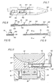
- the bracket holder 94 which is shown in details in Figs. 7-10 and described hereinbelow, fits tightly within the shallow groove portion 96 and accurately positions a buccal bracket relative to a selected position the tooth in question.
- the selected point of bracket application is in the central region of the tooth and at or near the center point 46 of the sphere 48.
- a quantity of water soluble cement, bonding material or other suitable material is employed to secure the buccal bracket temporarily to the buccal surface of the tooth in accordance with conventional indirect bonding procedure.
- bracket holder 94 For attachment of orthodontic brackets to the lingual surface of the tooth in question the bracket holder 94 will itself be positioned in the manner shown in Fig. 1.
- the bracket holder which is discussed in detail hereinbelow in connection with Figs. 7-10, includes a gripping portion receivable within the archwire slot of the bracket and thus provides support for the bracket during positioning relative to the tooth.
- the bracket is cemented to the tooth by a water soluble cement in accordance with conventional indirect bonding technique.
- a position translation pedestal 96 is secured to the base 16 by means of bolts 98 and thus is in fixed relation to the base 16 and to the tooth orienting pedestal 66.
- the upper portion of the position translation pedestal defines a bore 98 receiving a guide sleeve 100 in fixed relation therein.
- the guide sleeve 100 forms an inner cylindrical guide surface 102 receiving the outer cylindrical surface 104 of a coarse adjustment member 106 in close fitting relation therewith.
- a lock member 108 is threadedly received by the upper portion of the position translation pedestal and is adapted to engage and establish locking relation with the coarse adjustment member 106.
- the coarse adjustment member in turn defines an internal blind bore forming an internal guide surface 110.
- the outer portion of the blind bore is closed by means of a bushing member 112 which is threadedly received by the coarse adjustment member 106.
- the bushing 112 defines a cylindrical bearing surface 114 which provides a guiding function for a bracket positioning shaft 116.
- a guiding enlargement 118 At the internal end of the bracket positioning shaft is provided a guiding enlargement 118 which is received in close fitting relation with the inner cylindrical guide surface 110.
- a shaft orienting pin 120 extends transversely through the enlarged portion 118 of the shaft 116 with opposed end portions thereof received by guide slots 122 and 124 of the coarse adjustment member 106 and opposed slots 126 and 128 defined by the sleeve member 100.
- the bracket positioning shaft 116 and the coarse adjustment member 106 are prevented from any degree of rotation. These components simply move linearly relative to the upper portion of the position translation pedestal.
- a connector block 130 which is fixed to the free extremity of the bracket positioning shaft 116 is secured to a bracket holder block 132 by means of screw members 134.
- a vertically movable bracket holder slide 131 is received within a dove-tail slot 133 of the bracket holder block 132 and is vertically movable by a positioning screw member 135.
- the slide is accurately guided by the dovetail slot and by a guide pin 137.
- the guide pin is spring loaded by a spring 139 to apply a continuous force against the slide to compensate for thread looseness and permit accurate slide positioning.
- the bracket holder slide 131 forms a vertically oriented recess 136 which receives the bracket holder 94 in positively aligned and oriented relation with respect to the bracket holder slide.
- bracket holder may be secured to the bracket holder slide in any suitable fashion, the embodiment illustrated in Figs. 1-3 accomplishes magnetic retention of the bracket holder.
- Upper and lower magnets 138 and 140 are secured within the bracket holder slide 131 and provide magnetic retention of the bracket holder.
- the position of the bracket holder relative to the bracket holder slide 131 is accurately controlled by a stop element 169 shown in Fig. 2.
- Reference indicia is provided on the bracket holder slide 131 and the position of the bracket holder is adjusted vertically until a reference element 142 on the bracket holder block 132 registers with the reference indicia.
- an indicia bearing member 144 is secured to the upper portion of the position translation pedestal 96.
- a reference member 146 extending from the connector block 130 is provided with a mark that may be brought into registry with appropriate indicia on member 144. Through proper positioning of the reference mark relative to the indicia on member 144 the position of the bracket supported by the bracket holder may be effectively oriented in appropriately translated relation with respect to the buccal surface of the tooth.
- bracket positioning shaft 116 For fine adjustment of the bracket positioning shaft 116 a compression spring member 148 surrounding the shaft is positioned with its respective ends bearing against the bushing member 112 and the enlargement 118. The compression spring urges the bracket positioning. shaft 116 toward the right as shown in Fig. 1.
- a fine adjustment screw member 150 is threadedly received by the coarse adjustment member 106 and is rotatable clockwise or counter clockwise for appropriate positioning of the shaft 116 relative to the coarse adjustment member.
- the bracket holder includes means for both coarse and fine adjustment to enable the user to simply and efficiently achieve optimum positioning of the lingual bracket.
- the bracket holder shown generally at 94 comprises an elongated strip member 152 which may be provided with indicia in the form of measurement marks 154 which enable the bracket holder to be accurately positioned relative to the reference mark 156 of Fig. 4 for accurate positioning of orthodontic brackets in the buccal mode.
- To the elongated strip member 152 is secured a pair of spaced shorter strip members 158 and 159 which cooperate with spacer strips 161 and with strip member 152 to define a pocket or receptacle 160 receiving a locking slide member 162.
- the slide 162 forms a transversely projecting member 163 and the short strip 159 has a transversely projecting fixed member 165.
- the strip members 152 and 158 form bracket gripping ends 164 and 166 respectively which are bent toward one another such that the end portions in the collapsed positions thereof are ordinarily in substantial contact in the manner shown in Fig. 8.
- the ends 164 and 166 have a combined thickness which is less than the width of the archwire slot of the bracket to be supported thereby. This feature enables the ends 164 and 166 to be easily inserted into the archwire slot of an orthodontic bracket.
- the strip members 152 and 158 are composed of a resilient material such as stainless spring steps and are thus movable from the collapsed position shown in Fig.
- the bracket holder also provides a stop member 169 which engages the upper shoulder 171 of the bracket holder slide 131 to limit further downward movement and achieve precise positioning of the bracket holder device relative to the bracket holder slide.
- one suitable means for stabilizing the model 14 may conveniently take the form of a vacuum induced locking system which releasably fixes the model support element 42 relative to the support block 36. This feature is shown in Figs. 1 and 2 and is shown by way of an alternative embodiment in Fig. 11. As shown in Fig. 11 the support block 36 defines a piston bore 168 which is in communication with the concave spherical surface segment 40 of the support block by means of a connecting passage 170.
- a piston member 172 is movably disposed within the piston chamber and is sealed by means of an annular sealing member 174.
- the volume of the piston chamber increases and thus develops a negative pressure or vacuum which is communicated via the connecting passage 170 to the spherical interface between spherical surface segments 40 and 44.
- This vacuum condition causes the model support 42 to be seated tightly against the spherical surface 40 of the support block thus inducing frictional locking of the support block.
- the piston moves to the left the volume of the piston chamber diminishes thus increasing the pressure that is communicated to the spherical interface between surfaces 40 and 44. In this unlocked condition the model support element 42 is readily movable relative to the support block.
- Linear movement of the piston is accomplished according to Fig. 11 by a rotary/linear actuator mechanism.
- An actuator pin 176 received by the support block 36 extends slightly into the piston bore 168 and is received by a helical slot 178 formed in an actuator extension 180 of the piston.
- the actuator extension is provided with an operating handle 182 which may be manually rotated to accomplish linear and rotary movement of the piston member for vacuum locking and unlocking.
- a connector passage 184 is provided which communicates a vacuum passage 186 with the interface between spherical surface segments 40 and 44.
- the vacuum passage 186 extends through the support block and terminates at an external connector element 188 shown in Fig. 2.
- the external connector is adapted to receive a vacuum tube coupled with a suitable source of vacuum, not shown.
- the vacuum source may be a vacuum pump or a vacuum system such as is commonly found in dental offices.
- FIGs. 12 and 13 an alternative embodiment of the present invention is illustrated which includes a turret apparatus for supporting a plurality of tooth guide elements which may be selectively positioned relative to selected teeth of a dental model.
- a major portion of the apparatus of Figs. 12 and 13 may be substantially identical to features set forth in the apparatus of Figs. 1-3. Accordingly, like parts are illustrated by like reference numerals.
- a tooth orienting pedestal 190 is secured in immovable relation to the base 16 by means of connector bolts 68.
- the tooth orienting pedestal defines a blind bore 192 within which is fixed a turret shaft 194.
- a turret member 196 forms a blind bore 198 within which is received the outer extremity 200 of the turret shaft 194.
- the surface forming the blind bore 198 functions as a bushing surface establishing a precise, rotatable fitting relation with the outer cylindrical surface 202 of the turret shaft.
- a ball detent locking member 204 is received within a transverse bore of the turret shaft 194 and is urged outwardly by means of a compression spring 206.
- the ball detent is receivable within selected ones of a plurality of detent recesses 208.
- the turret member 196 is provided with a plurality of tooth guide elements 210 which are in fixed relation with the turret.
- Each of the guide elements is provided with a guide blade or template 212 forming an appropriate guide surface for a particular tooth.
- the selected tooth or teeth to which the guide surface relates may be precisely positioned by appropriate manipulation of the position of the model in the manner discussed above.
- the position of the model is stabilized such as by energization of the vacuum locking system to permit cementing of a bracket to the buccal or lingual surface of the tooth.
- the turret 196 is provided with a bracket positioning receptacle 216 which receives the bracket holder 94. With the model stabilized the turret is rotated to align the bracket positioning receptacle 216 with a selected tooth of the model. The bracket holder is inserted within the receptacle 216 and is appropriately positioned relative to a reference mark 218 to thus accurately establish positioning of the archwire slot relative to the tooth of the model.
- the bracket holder 94 is again utilized but is positioned in substantially vertical manner as shown in Fig. 1.
Landscapes
- Health & Medical Sciences (AREA)
- Oral & Maxillofacial Surgery (AREA)
- Dentistry (AREA)
- Epidemiology (AREA)
- Life Sciences & Earth Sciences (AREA)
- Animal Behavior & Ethology (AREA)
- General Health & Medical Sciences (AREA)
- Public Health (AREA)
- Veterinary Medicine (AREA)
- Dental Tools And Instruments Or Auxiliary Dental Instruments (AREA)
Applications Claiming Priority (2)
| Application Number | Priority Date | Filing Date | Title |
|---|---|---|---|
| US33721 | 1987-04-03 | ||
| US07/033,721 US4812118A (en) | 1987-04-03 | 1987-04-03 | Placement apparatus for lingual and buccal brackets |
Publications (3)
| Publication Number | Publication Date |
|---|---|
| EP0285418A2 true EP0285418A2 (fr) | 1988-10-05 |
| EP0285418A3 EP0285418A3 (en) | 1989-07-26 |
| EP0285418B1 EP0285418B1 (fr) | 1992-12-23 |
Family
ID=21872068
Family Applications (1)
| Application Number | Title | Priority Date | Filing Date |
|---|---|---|---|
| EP88302886A Expired EP0285418B1 (fr) | 1987-04-03 | 1988-03-30 | Dispositif pour la pose de bagues linguales et buccales |
Country Status (7)
| Country | Link |
|---|---|
| US (1) | US4812118A (fr) |
| EP (1) | EP0285418B1 (fr) |
| JP (1) | JPS63270046A (fr) |
| AU (1) | AU613609B2 (fr) |
| CA (1) | CA1309281C (fr) |
| DE (1) | DE3876832T2 (fr) |
| MX (1) | MX169029B (fr) |
Cited By (5)
| Publication number | Priority date | Publication date | Assignee | Title |
|---|---|---|---|---|
| FR2655838A1 (fr) * | 1989-12-19 | 1991-06-21 | Vielfaure Guy | Procede et dispositif de pose d'attaches, notamment de type lingual, pour appareil d'orthodontie. |
| FR2706281A1 (fr) * | 1993-06-17 | 1994-12-23 | Huet Alain Pierre | Appareil de mise en position utilisable en art dentaire. |
| DE4038892C2 (de) * | 1989-12-15 | 2000-04-20 | Bernhard Geis | Verfahren und Vorrichtung zur Vermessung von Kiefermodellen |
| WO2007073143A1 (fr) * | 2005-12-21 | 2007-06-28 | Marichi Rodriguez Francisco Ja | Appareil de mesure de programmation et de soudage de brackets ajustables |
| US8038438B2 (en) | 2005-12-21 | 2011-10-18 | Roberto Ruiz Diaz | Totally adjustable bracket system |
Families Citing this family (25)
| Publication number | Priority date | Publication date | Assignee | Title |
|---|---|---|---|---|
| US4909735A (en) * | 1988-09-26 | 1990-03-20 | Wildman Alexander J | Straight line orthodontic setup method and apparatus |
| US5011406A (en) * | 1988-09-26 | 1991-04-30 | Wildman Alexander J | Orthodontic setup and archwire fixing method |
| GB8826896D0 (en) * | 1988-11-17 | 1988-12-21 | Univ Sheffield | Articulators for constructing artificial teeth |
| US5028232A (en) * | 1989-05-03 | 1991-07-02 | Snow Michael D | Apparatus and method for calibrating physiologic dental occlusion and determining optimal individual orthodontic appliance prescription |
| US5064368A (en) * | 1989-12-28 | 1991-11-12 | Lavin Joseph J | Indexing device for placement of orthodontic brackets |
| US5320527A (en) * | 1992-02-03 | 1994-06-14 | Robert Schwartz | Dental arch form |
| CA2139527C (fr) * | 1995-01-04 | 1999-05-11 | Jui-Yuan Shih | Methode et appareil servant a enregistrer et a reproduire l'axe d'insertion d'un moulage sur des paralleliseurs |
| WO1998006347A1 (fr) * | 1996-08-12 | 1998-02-19 | Silvia Geron | Appareil et procede pour la mise en place d'attachements linguaux |
| US6123544A (en) * | 1998-12-18 | 2000-09-26 | 3M Innovative Properties Company | Method and apparatus for precise bond placement of orthodontic appliances |
| EP1482857B1 (fr) * | 2002-03-13 | 2013-01-16 | Christoph Von Mandach | Set d'orthodontie |
| US20070099146A1 (en) * | 2002-12-31 | 2007-05-03 | Reising Brian C | System and method for positioning orthodontic brackets on a virtual model of a patient's teeth |
| US8251699B2 (en) | 2002-12-31 | 2012-08-28 | Brian C. Reising | Orthodontic bracket and method of attaching orthodontic brackets to teeth |
| US20050003324A1 (en) * | 2002-12-31 | 2005-01-06 | Reising Brian C. | Orthodontic bracket positioning device and method |
| US20040157184A1 (en) * | 2002-12-31 | 2004-08-12 | Reising Brian C. | Orthodontic bracket and method of attaching orthodontic brackets to teeth |
| US20040166463A1 (en) * | 2003-02-26 | 2004-08-26 | Align Technology, Inc. | Systems and methods for combination treatments of dental patients |
| US20040166462A1 (en) | 2003-02-26 | 2004-08-26 | Align Technology, Inc. | Systems and methods for fabricating a dental template |
| US7020963B2 (en) * | 2003-05-02 | 2006-04-04 | 3M Innovative Properties Company | Method and apparatus for indirect bonding of orthodontic appliances |
| US7347688B2 (en) * | 2004-04-15 | 2008-03-25 | Cadent Ltd. | Dental targetting device and method |
| US20050244768A1 (en) * | 2004-04-28 | 2005-11-03 | Eldad Taub | Device and method for applying an abutment force between dental appliance and teeth |
| WO2009070480A1 (fr) * | 2007-11-29 | 2009-06-04 | 3M Innovative Properties Company | Procédés et appareils pour appliquer un mastic dentaire sur les dents d'un patient d'orthodontie |
| WO2009075977A1 (fr) * | 2007-12-13 | 2009-06-18 | 3M Innovative Properties Company | Article orthodontique contenant une composition partiellement durcie, procede de fabrication et methode d'utilisation associes |
| JP5362383B2 (ja) * | 2009-02-18 | 2013-12-11 | 有限会社オーソスターシオン | ブラケット取り付け治具 |
| US8936464B2 (en) | 2009-02-24 | 2015-01-20 | Cadent Ltd. | Method, system and model for indirect bonding |
| CN104783912B (zh) * | 2015-03-30 | 2023-06-09 | 高原 | 用于牙齿内侧的矫正牙套制作方法及牙齿矫正组合器件 |
| CN105105856B (zh) * | 2015-09-18 | 2017-11-28 | 上海市徐汇区牙病防治所 | 预置正畸托槽序列弯曲的装置 |
Family Cites Families (24)
| Publication number | Priority date | Publication date | Assignee | Title |
|---|---|---|---|---|
| US2613440A (en) * | 1950-03-20 | 1952-10-14 | Addie P Murray | Articulator for making artificial dentures |
| US2669780A (en) * | 1953-02-05 | 1954-02-23 | Arvin W Mann | Pin centering and paralleling instrument |
| US3439421A (en) * | 1967-01-09 | 1969-04-22 | Thomas E Perkowski | Method of making orthodontic appliances |
| US3686762A (en) * | 1971-08-02 | 1972-08-29 | Robert E Sutter | Orthodontic applicator tool |
| US3738005A (en) * | 1972-03-22 | 1973-06-12 | M Cohen | Method and apparatus for applying orthodontic brackets and the like |
| US3871098A (en) * | 1972-08-03 | 1975-03-18 | J Thomas Dean | Bracket placer |
| US3949478A (en) * | 1974-12-27 | 1976-04-13 | Firma Scheu-Dental, Inhaber Rudolf Scheu Herstellung Und Vertrieb Von Dentalbedarf | Process and apparatus for fitting orthodontic brackets to teeth |
| US4001940A (en) * | 1975-02-19 | 1977-01-11 | Henry Mann, Inc. | Elastic positioner apparatus for orthodontists |
| US4014096A (en) * | 1975-03-25 | 1977-03-29 | Dellinger Eugene L | Method and apparatus for orthodontic treatment |
| US4017972A (en) * | 1975-07-07 | 1977-04-19 | Glenn Edward C | Dowel pin positioner |
| US4035919A (en) * | 1976-06-04 | 1977-07-19 | Dentronix, Inc. | Direct bonding bracket positioning and mounting tool |
| US4183141A (en) * | 1977-12-05 | 1980-01-15 | Dellinger Eugene L | Method and apparatus for treating malocclusion |
| US4360341A (en) * | 1981-03-16 | 1982-11-23 | Dellinger Eugene L | Orthodontic method for treating malocclusion |
| US4474555A (en) * | 1981-11-17 | 1984-10-02 | Diamond Michael K | Dental instrument and method for positioning an orthodontic bracket |
| US4455137A (en) * | 1981-11-17 | 1984-06-19 | Diamond Michael K | Dental instrument and method for positioning a lingual orthodontic bracket |
| US4422849A (en) * | 1981-11-17 | 1983-12-27 | Diamond Michael K | Dental instrument and method for positioning a lingual orthodontic bracket |
| US4431409A (en) * | 1982-01-15 | 1984-02-14 | Picard Peter J | Orthodontic apparatus |
| US4523540A (en) * | 1982-04-12 | 1985-06-18 | The Continental Group, Inc. | Adhesive applicator |
| US4424029A (en) * | 1982-06-01 | 1984-01-03 | Baxter Travenol Laboratories, Inc. | Lingual placement device |
| US4478576A (en) * | 1982-06-01 | 1984-10-23 | Romada Holdings Ltd. | Orthodontic attachment placement device |
| US4494931A (en) * | 1982-10-15 | 1985-01-22 | Wildman Alexander J | Method and pad with index tabs for applying orthodontic brackets |
| US4501554A (en) * | 1983-07-25 | 1985-02-26 | Hickham John H | Two tray indirect bonding system for labial and lingual brackets |
| US4551096A (en) * | 1983-12-19 | 1985-11-05 | Dellinger Eugene L | Orthodontic apparatus and method for treating malocclusion |
| US4526540A (en) * | 1983-12-19 | 1985-07-02 | Dellinger Eugene L | Orthodontic apparatus and method for treating malocclusion |
-
1987
- 1987-04-03 US US07/033,721 patent/US4812118A/en not_active Expired - Lifetime
-
1988
- 1988-03-14 CA CA000561428A patent/CA1309281C/fr not_active Expired - Lifetime
- 1988-03-29 AU AU13835/88A patent/AU613609B2/en not_active Ceased
- 1988-03-29 MX MX010930A patent/MX169029B/es unknown
- 1988-03-30 EP EP88302886A patent/EP0285418B1/fr not_active Expired
- 1988-03-30 DE DE8888302886T patent/DE3876832T2/de not_active Expired - Fee Related
- 1988-04-04 JP JP63082862A patent/JPS63270046A/ja active Pending
Cited By (7)
| Publication number | Priority date | Publication date | Assignee | Title |
|---|---|---|---|---|
| DE4038892C2 (de) * | 1989-12-15 | 2000-04-20 | Bernhard Geis | Verfahren und Vorrichtung zur Vermessung von Kiefermodellen |
| FR2655838A1 (fr) * | 1989-12-19 | 1991-06-21 | Vielfaure Guy | Procede et dispositif de pose d'attaches, notamment de type lingual, pour appareil d'orthodontie. |
| FR2706281A1 (fr) * | 1993-06-17 | 1994-12-23 | Huet Alain Pierre | Appareil de mise en position utilisable en art dentaire. |
| WO1995000079A1 (fr) * | 1993-06-17 | 1995-01-05 | Huet Alain Pierre | Appareil de mise en position utilisable en art dentaire |
| WO2007073143A1 (fr) * | 2005-12-21 | 2007-06-28 | Marichi Rodriguez Francisco Ja | Appareil de mesure de programmation et de soudage de brackets ajustables |
| US7721456B2 (en) | 2005-12-21 | 2010-05-25 | Francisco Javier Marichi Rodriguez | Measuring apparatus for the programming and welding of adjustable brackets |
| US8038438B2 (en) | 2005-12-21 | 2011-10-18 | Roberto Ruiz Diaz | Totally adjustable bracket system |
Also Published As
| Publication number | Publication date |
|---|---|
| CA1309281C (fr) | 1992-10-27 |
| EP0285418B1 (fr) | 1992-12-23 |
| DE3876832T2 (de) | 1993-06-03 |
| AU613609B2 (en) | 1991-08-08 |
| EP0285418A3 (en) | 1989-07-26 |
| MX169029B (es) | 1993-06-17 |
| US4812118A (en) | 1989-03-14 |
| DE3876832D1 (de) | 1993-02-04 |
| JPS63270046A (ja) | 1988-11-08 |
| AU1383588A (en) | 1988-10-06 |
Similar Documents
| Publication | Publication Date | Title |
|---|---|---|
| EP0285418B1 (fr) | Dispositif pour la pose de bagues linguales et buccales | |
| US3949478A (en) | Process and apparatus for fitting orthodontic brackets to teeth | |
| US5100316A (en) | Orthodontic archwire shaping method | |
| US8235717B2 (en) | Method and apparatus for indirect bonding of orthodontic appliances to teeth | |
| US4183141A (en) | Method and apparatus for treating malocclusion | |
| US4634377A (en) | Device for aligning artificial teeth and crowns | |
| US4455137A (en) | Dental instrument and method for positioning a lingual orthodontic bracket | |
| US5295886A (en) | Orthodontic archwire shaping method and archwire-segment forming templates | |
| EP3636213B1 (fr) | Gabarit d'alignement de prothèse dentaire de référence, kit de préparation de prothèses dentaires, et procédé de préparation de prothèses dentaires utilisant ce dernier | |
| US4687442A (en) | Surgical articulator apparatus and method | |
| US3439421A (en) | Method of making orthodontic appliances | |
| JP2001212159A (ja) | 歯列矯正用ブラケット取付装置 | |
| US20050003324A1 (en) | Orthodontic bracket positioning device and method | |
| US4277237A (en) | Jaw implant measuring instrument | |
| US5281135A (en) | Articulator for cast surgery and method of use | |
| US2510152A (en) | Dental surveyor and coordinator | |
| US4431409A (en) | Orthodontic apparatus | |
| US5011406A (en) | Orthodontic setup and archwire fixing method | |
| US4422849A (en) | Dental instrument and method for positioning a lingual orthodontic bracket | |
| US4017972A (en) | Dowel pin positioner | |
| US4547154A (en) | Device for the encapsulation in plaster of models of the jaw for the manufacture of dental prostheses | |
| US4474555A (en) | Dental instrument and method for positioning an orthodontic bracket | |
| US3722099A (en) | Method of accurately and precisely constructing artificial dentures | |
| KR102264164B1 (ko) | 디지털 오버덴쳐 홀더장치용 고정바 벤딩장치 | |
| US4909735A (en) | Straight line orthodontic setup method and apparatus |
Legal Events
| Date | Code | Title | Description |
|---|---|---|---|
| PUAI | Public reference made under article 153(3) epc to a published international application that has entered the european phase |
Free format text: ORIGINAL CODE: 0009012 |
|
| AK | Designated contracting states |
Kind code of ref document: A2 Designated state(s): CH DE FR GB IT LI |
|
| PUAL | Search report despatched |
Free format text: ORIGINAL CODE: 0009013 |
|
| AK | Designated contracting states |
Kind code of ref document: A3 Designated state(s): CH DE FR GB IT LI |
|
| 17P | Request for examination filed |
Effective date: 19900104 |
|
| 17Q | First examination report despatched |
Effective date: 19910523 |
|
| ITF | It: translation for a ep patent filed | ||
| GRAA | (expected) grant |
Free format text: ORIGINAL CODE: 0009210 |
|
| AK | Designated contracting states |
Kind code of ref document: B1 Designated state(s): CH DE FR GB IT LI |
|
| REF | Corresponds to: |
Ref document number: 3876832 Country of ref document: DE Date of ref document: 19930204 |
|
| ET | Fr: translation filed | ||
| PLBE | No opposition filed within time limit |
Free format text: ORIGINAL CODE: 0009261 |
|
| STAA | Information on the status of an ep patent application or granted ep patent |
Free format text: STATUS: NO OPPOSITION FILED WITHIN TIME LIMIT |
|
| 26N | No opposition filed | ||
| PGFP | Annual fee paid to national office [announced via postgrant information from national office to epo] |
Ref country code: GB Payment date: 19940321 Year of fee payment: 7 |
|
| PGFP | Annual fee paid to national office [announced via postgrant information from national office to epo] |
Ref country code: DE Payment date: 19940323 Year of fee payment: 7 Ref country code: CH Payment date: 19940323 Year of fee payment: 7 |
|
| PGFP | Annual fee paid to national office [announced via postgrant information from national office to epo] |
Ref country code: FR Payment date: 19940324 Year of fee payment: 7 |
|
| PG25 | Lapsed in a contracting state [announced via postgrant information from national office to epo] |
Ref country code: GB Effective date: 19950330 |
|
| PG25 | Lapsed in a contracting state [announced via postgrant information from national office to epo] |
Ref country code: LI Effective date: 19950331 Ref country code: CH Effective date: 19950331 |
|
| GBPC | Gb: european patent ceased through non-payment of renewal fee |
Effective date: 19950330 |
|
| PG25 | Lapsed in a contracting state [announced via postgrant information from national office to epo] |
Ref country code: FR Free format text: LAPSE BECAUSE OF NON-PAYMENT OF DUE FEES Effective date: 19951130 |
|
| REG | Reference to a national code |
Ref country code: CH Ref legal event code: PL |
|
| PG25 | Lapsed in a contracting state [announced via postgrant information from national office to epo] |
Ref country code: DE Effective date: 19951201 |
|
| REG | Reference to a national code |
Ref country code: FR Ref legal event code: ST |
|
| PG25 | Lapsed in a contracting state [announced via postgrant information from national office to epo] |
Ref country code: IT Free format text: LAPSE BECAUSE OF NON-PAYMENT OF DUE FEES Effective date: 20050330 |