EP0285537A1 - Heuerntemaschine - Google Patents
Heuerntemaschine Download PDFInfo
- Publication number
- EP0285537A1 EP0285537A1 EP88440025A EP88440025A EP0285537A1 EP 0285537 A1 EP0285537 A1 EP 0285537A1 EP 88440025 A EP88440025 A EP 88440025A EP 88440025 A EP88440025 A EP 88440025A EP 0285537 A1 EP0285537 A1 EP 0285537A1
- Authority
- EP
- European Patent Office
- Prior art keywords
- tool
- arm
- carrying
- haymaking machine
- machine according
- Prior art date
- Legal status (The legal status is an assumption and is not a legal conclusion. Google has not performed a legal analysis and makes no representation as to the accuracy of the status listed.)
- Granted
Links
Images
Classifications
-
- A—HUMAN NECESSITIES
- A01—AGRICULTURE; FORESTRY; ANIMAL HUSBANDRY; HUNTING; TRAPPING; FISHING
- A01D—HARVESTING; MOWING
- A01D78/00—Haymakers with tines moving with respect to the machine
- A01D78/08—Haymakers with tines moving with respect to the machine with tine-carrying rotary heads or wheels
- A01D78/10—Haymakers with tines moving with respect to the machine with tine-carrying rotary heads or wheels the tines rotating about a substantially vertical axis
- A01D78/12—Haymakers with tines moving with respect to the machine with tine-carrying rotary heads or wheels the tines rotating about a substantially vertical axis the tines having an additional movement superimposed upon their rotary movement
- A01D78/125—Haymakers with tines moving with respect to the machine with tine-carrying rotary heads or wheels the tines rotating about a substantially vertical axis the tines having an additional movement superimposed upon their rotary movement by a guiding track
-
- A—HUMAN NECESSITIES
- A01—AGRICULTURE; FORESTRY; ANIMAL HUSBANDRY; HUNTING; TRAPPING; FISHING
- A01D—HARVESTING; MOWING
- A01D78/00—Haymakers with tines moving with respect to the machine
- A01D78/08—Haymakers with tines moving with respect to the machine with tine-carrying rotary heads or wheels
- A01D78/10—Haymakers with tines moving with respect to the machine with tine-carrying rotary heads or wheels the tines rotating about a substantially vertical axis
- A01D78/12—Haymakers with tines moving with respect to the machine with tine-carrying rotary heads or wheels the tines rotating about a substantially vertical axis the tines having an additional movement superimposed upon their rotary movement
-
- A—HUMAN NECESSITIES
- A01—AGRICULTURE; FORESTRY; ANIMAL HUSBANDRY; HUNTING; TRAPPING; FISHING
- A01D—HARVESTING; MOWING
- A01D80/00—Parts or details of, or accessories for, haymakers
- A01D80/02—Tines; Attachment of tines
Definitions
- the present invention relates to a haymaking machine intended in particular for raking hay and comprising at least one raking wheel driven in rotation during work.
- This raking wheel is provided with tool-carrying arms controlled so that, at each revolution, they pivot around their respective longitudinal axes with a view to removing the raked fodder.
- the tool-carrying arms are practically rectilinear and comprise near their outer ends working tools. These are generally in the form of forks fitted with turns to increase their flexibility. These forks are all essentially on the same side with respect to the longitudinal pivot axes of their support arms. As a result, there are significant imbalances in these arms when they pivot around said axes during work. These unbalances cause vibrations of the machine and rapid wear of the guide bearings of these tool-carrying arms and of the mechanism which controls their pivoting.
- the object of the present invention is in particular to improve the arrangement of the carrying arms and working tools, in order to increase the reliability of these machines and to obtain better operation.
- an important characteristic of the invention consists in that at least the external part of each arm, on which the working tools are fixed, is offset with respect to the internal part of the same arm so that the center of gravity of each assembly including said outer part and the working tools is located approximately on the pivot axis of the corresponding tool-carrying arm. Thanks to this arrangement, all of the parts which pivot around the longitudinal axes of the tool-carrying arms are balanced. Therefore, the operation of the machine according to the invention is much more regular and the wear of the bearings of the tool-carrying arms and of the control mechanism of the latter is much less rapid.
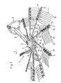
- the machine comprises a raking wheel (1) connected to one end of a carrying beam (2).
- the front end of this beam (2) carries a three-point hitch trestle (3) for coupling to a drive tractor not shown.
- the raking wheel (1) has a central housing (4) or the like, which is traversed by a substantially vertical carrying axis (5). The lower end of this axis is connected to a set of wheels (6) allowing the machine to move on the ground during work.
- the housing (4) consists of a fixed upper part (7) which is linked to the support axis (5) and to the beam (2) and, of a movable lower part (8).
- This movable part (8) can move in rotation around said carrier axis (5). At work, it is rotated in the direction of the arrow (F) from the PTO shaft of the tractor.
- this shaft is connected via a transmission shaft to a drive shaft housed in the fixed part (7) of the housing (4).
- the aforementioned drive shaft comprises a pinion which meshes with a toothed crown secured to the movable part (8) of the housing (4).
- Said movable part (8) carries several bearings (9) in which are guided tool-carrying arms (10).
- These arms (10) can be made in one or more pieces. They extend in the form of spokes towards the outside and have working tools (11) near their outer ends.
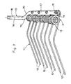
- This fixing is ensured by means of bolts (15) which pass through said loop (14) and pass through the tool-carrying arms (10) (see FIG. 2).
- Each arm (10) advantageously comprises four forks (12) placed side by side. This arrangement of the forks (12) makes it possible to replace any of them, for example in the event of one of the strands breaking, without it being necessary to dismantle the neighboring fork or forks.
- each tool arm (10) enters the movable part (8) of the housing (4). Inside it it comprises in a manner known per se a crank provided with a roller which moves in a motionless control cam.
- This cam is fixed on the carrier axle (5) of the raking wheel. It has a level portion so that the aforementioned rollers move in height over part of their trajectory. During this movement, the rollers actuate the tool-carrying arms (10) by means of the cranks.
- each tool-carrying arm (10) on which the working tools (11) are fixed is offset with respect to the interior part (18) of the same arm, so that the center of gravity (G) of each set comprising said outer part (17) and the working tools (11), is situated substantially on the longitudinal pivot axis (16) of the corresponding arm (10).
- the moving parts around this axis (16) are thus balanced. Therefore, there is no impact at each pivoting on the guide bearings (9) and the control means of the arms (10).
- each arm (10) is offset with respect to the pivot axis (16) towards the side opposite to that on which the major part of the working tools are located. (11).
- This arrangement allows the latter to be brought closer to the pivot axis (16) and to balance the weight of the tools (11) partly at least by means of the arms (10) themselves.
- This offset can be achieved as shown, by providing on each tool-carrying arm (10), two elbows (19 and 20) located one after the other and which are directed in opposite directions.
- This offset can also be obtained by making each tool-carrying arm (10) in two separate parts which are offset with respect to each other and connected to each other by means of a cross-member.
- each tool-carrying arm (10) is substantially parallel to one another. This characteristic makes it possible in particular to properly control the position of the working tools (11) both in the raking area and during their pivoting for the release of the forage and the formation of the swath.
Landscapes
- Environmental Sciences (AREA)
- Life Sciences & Earth Sciences (AREA)
- Control Of Multiple Motors (AREA)
- Paper (AREA)
- Harvesting Machines For Specific Crops (AREA)
- Glass Compositions (AREA)
- Harvester Elements (AREA)
- Coating With Molten Metal (AREA)
- Macromolecular Compounds Obtained By Forming Nitrogen-Containing Linkages In General (AREA)
- Photoreceptors In Electrophotography (AREA)
- Sampling And Sample Adjustment (AREA)
- Separation By Low-Temperature Treatments (AREA)
- Agricultural Machines (AREA)
Priority Applications (1)
| Application Number | Priority Date | Filing Date | Title |
|---|---|---|---|
| AT88440025T ATE63664T1 (de) | 1987-04-01 | 1988-03-23 | Heuerntemaschine. |
Applications Claiming Priority (2)
| Application Number | Priority Date | Filing Date | Title |
|---|---|---|---|
| FR8704672 | 1987-04-01 | ||
| FR8704672A FR2613177B1 (fr) | 1987-04-01 | 1987-04-01 | Machine de fenaison |
Publications (2)
| Publication Number | Publication Date |
|---|---|
| EP0285537A1 true EP0285537A1 (de) | 1988-10-05 |
| EP0285537B1 EP0285537B1 (de) | 1991-05-22 |
Family
ID=9349736
Family Applications (1)
| Application Number | Title | Priority Date | Filing Date |
|---|---|---|---|
| EP88440025A Expired - Lifetime EP0285537B1 (de) | 1987-04-01 | 1988-03-23 | Heuerntemaschine |
Country Status (7)
| Country | Link |
|---|---|
| US (1) | US4875332A (de) |
| EP (1) | EP0285537B1 (de) |
| AT (1) | ATE63664T1 (de) |
| DE (1) | DE3862885D1 (de) |
| DK (1) | DK164352C (de) |
| ES (1) | ES2023007B3 (de) |
| FR (1) | FR2613177B1 (de) |
Cited By (2)
| Publication number | Priority date | Publication date | Assignee | Title |
|---|---|---|---|---|
| NL1009827C2 (nl) * | 1998-08-10 | 2000-02-11 | Maasland Nv | Harkmachine. |
| NL1034442C2 (nl) * | 2007-09-28 | 2009-03-31 | Lely Patent Nv | Hooibouwinrichting voor het verplaatsen van op de grond liggend gewas. |
Families Citing this family (15)
| Publication number | Priority date | Publication date | Assignee | Title |
|---|---|---|---|---|
| FR2678804B1 (fr) * | 1991-07-11 | 1998-09-18 | Kuhn Sa | Machine de fenaison comportant au moins une roue rateleuse, un dispositif de protection et un deflecteur reglable. |
| US5377482A (en) * | 1993-09-03 | 1995-01-03 | Miller-St. Nazianz, Inc. | Hydraulic lift rotary rake |
| FR2718324B1 (fr) * | 1994-04-12 | 1996-06-14 | Kuhn Sa | Machine de fenaison, notamment un andaineur, avec au moins un dispositif d'arrêt du rotor. |
| FR2722365B1 (fr) * | 1994-07-13 | 1996-09-20 | Kuhn Sa Societe Anonyme | Machine de fenaison, notamment une andaineuse de vegetaux a bras porte-fourches commandes |
| FR2740652B1 (fr) * | 1995-11-07 | 1998-01-30 | Kuhn Sa | Machine de fenaison comportant au moins un rotor d'andainage et permettant notamment une meilleure adaptation du rotor au relief du terrain |
| FR2746577B1 (fr) * | 1996-03-29 | 1998-05-29 | Kuhn Sa | Machine de fenaison comportant un dispositif de protection deplacable |
| FR2754136B1 (fr) * | 1996-10-03 | 1999-01-22 | Kuhn Sa | Machine de fenaison comportant un chassis compose de plusieurs troncons articules entre eux |
| FR2756137B1 (fr) * | 1996-11-26 | 1999-01-22 | Kuhn Sa | Machine de fenaison, notamment une andaineuse avec un deflecteur d'andainage reglage automatiquement dans differentes positions |
| US6272826B1 (en) | 1999-04-29 | 2001-08-14 | Sitrex S.R.L. | Method and apparatus for positioning a hay rake |
| US6865873B2 (en) * | 2002-06-21 | 2005-03-15 | Sitrex S.R.L. | Pull type V-shaped hay rake |
| US6834488B2 (en) | 2002-11-22 | 2004-12-28 | Sitrex S.R.L. | Towable hay rake with an automatic steering mechanism |
| US7377093B2 (en) * | 2005-10-19 | 2008-05-27 | Cnh America Llc | Rotary crop inverter |
| FR2987223B1 (fr) * | 2012-02-29 | 2014-03-28 | Kuhn Sa | Rotor d'une machine de fenaison muni de bras en deux parties reliees par un dispositif de liaison perfectionne |
| JP6210918B2 (ja) * | 2014-03-27 | 2017-10-11 | 株式会社タカキタ | レーキ |
| US9839180B2 (en) | 2015-06-19 | 2017-12-12 | Sam Esch | Windrow forming agricultural rake assembly |
Citations (3)
| Publication number | Priority date | Publication date | Assignee | Title |
|---|---|---|---|---|
| DE2057370B1 (de) * | 1970-11-21 | 1971-11-25 | Fahr Ag Maschf | Heuwerbungsmaschine |
| CH535001A (de) * | 1969-05-16 | 1973-03-31 | Stoll Maschf Gmbh Wilhelm | Heuwerbungsmaschine |
| DE2918211A1 (de) * | 1979-05-05 | 1980-11-13 | Stoll Maschf Gmbh Wilhelm | Heuwerbungsmaschine |
Family Cites Families (10)
| Publication number | Priority date | Publication date | Assignee | Title |
|---|---|---|---|---|
| US3664105A (en) * | 1971-05-24 | 1972-05-23 | Sperry Rand Corp | Rake-tedding device |
| NL7209663A (de) * | 1972-07-13 | 1974-01-15 | ||
| FR2278239A1 (fr) * | 1974-07-18 | 1976-02-13 | Reber Walter | Machine de fenaison pour l'andainage comportant au moins deux roues rateleuses |
| NL7603683A (nl) * | 1976-04-08 | 1977-10-11 | Lely Nv C Van Der | Hooibouwmachine. |
| FR2382177A1 (fr) * | 1977-03-04 | 1978-09-29 | Kuhn Sa | Machine de fenaison pour l'andainage lateral de fourrage, a bras porte-outils commandes |
| US4105412A (en) | 1977-08-04 | 1978-08-08 | Petzinger Manfred W A | Portable compost container |
| FR2411553A1 (fr) * | 1977-12-16 | 1979-07-13 | Kuhn Sa | Machine de fenaison perfectionnee |
| NL7904687A (nl) * | 1978-08-25 | 1980-02-27 | Patent Concern Nv | Inrichting voor het verplaatsen van op de grond liggend gewas. |
| FR2450554B1 (fr) * | 1979-03-09 | 1985-07-05 | Belrecolt Sa | Perfectionnement aux machines de fenaison combinees |
| DE3107162A1 (de) * | 1981-02-26 | 1982-09-09 | Claas Saulgau GmbH, 7968 Saulgau | Heuwerbungsmaschine |
-
1987
- 1987-04-01 FR FR8704672A patent/FR2613177B1/fr not_active Expired - Fee Related
-
1988
- 1988-03-23 EP EP88440025A patent/EP0285537B1/de not_active Expired - Lifetime
- 1988-03-23 DE DE8888440025T patent/DE3862885D1/de not_active Expired - Fee Related
- 1988-03-23 ES ES88440025T patent/ES2023007B3/es not_active Expired - Lifetime
- 1988-03-23 AT AT88440025T patent/ATE63664T1/de not_active IP Right Cessation
- 1988-03-30 DK DK181388A patent/DK164352C/da not_active IP Right Cessation
- 1988-03-30 US US07/175,222 patent/US4875332A/en not_active Expired - Lifetime
Patent Citations (3)
| Publication number | Priority date | Publication date | Assignee | Title |
|---|---|---|---|---|
| CH535001A (de) * | 1969-05-16 | 1973-03-31 | Stoll Maschf Gmbh Wilhelm | Heuwerbungsmaschine |
| DE2057370B1 (de) * | 1970-11-21 | 1971-11-25 | Fahr Ag Maschf | Heuwerbungsmaschine |
| DE2918211A1 (de) * | 1979-05-05 | 1980-11-13 | Stoll Maschf Gmbh Wilhelm | Heuwerbungsmaschine |
Cited By (4)
| Publication number | Priority date | Publication date | Assignee | Title |
|---|---|---|---|---|
| NL1009827C2 (nl) * | 1998-08-10 | 2000-02-11 | Maasland Nv | Harkmachine. |
| EP0979600A1 (de) * | 1998-08-10 | 2000-02-16 | Maasland N.V. | Heuwerbungsmaschine |
| NL1034442C2 (nl) * | 2007-09-28 | 2009-03-31 | Lely Patent Nv | Hooibouwinrichting voor het verplaatsen van op de grond liggend gewas. |
| WO2009041807A1 (en) * | 2007-09-28 | 2009-04-02 | Lely Patent N.V. | Haymaking implement for displacing crop lying on the ground |
Also Published As
| Publication number | Publication date |
|---|---|
| DK181388D0 (da) | 1988-03-30 |
| DE3862885D1 (de) | 1991-06-27 |
| ATE63664T1 (de) | 1991-06-15 |
| DK164352B (da) | 1992-06-15 |
| DK164352C (da) | 1992-11-02 |
| DK181388A (da) | 1988-10-02 |
| EP0285537B1 (de) | 1991-05-22 |
| FR2613177B1 (fr) | 1991-06-28 |
| FR2613177A1 (fr) | 1988-10-07 |
| US4875332A (en) | 1989-10-24 |
| ES2023007B3 (es) | 1991-12-16 |
Similar Documents
| Publication | Publication Date | Title |
|---|---|---|
| EP0285537A1 (de) | Heuerntemaschine | |
| FR2654896A1 (fr) | Faucheuse comportant un groupe d'organes de travail s'etendant au travail transversalement a la direction d'avance. | |
| EP2253186B1 (de) | Heuwerbungsmaschine | |
| EP2839731A1 (de) | Futtererntemaschine | |
| FR2521823A1 (fr) | Dispositif pour deplacer de la matiere se trouvant sur le sol | |
| FR2663189A1 (fr) | Machine de fenaison pour l'andainage, comportant au moins deux roues rateleuses. | |
| EP1290936B1 (de) | Heuwerbungsmaschine | |
| FR2631208A1 (fr) | Perfectionnement aux machines agricoles avec un chassis porte-outils articule | |
| FR2517168A1 (fr) | Machine pour travailler le sol avec liaison elastique a un organe de soutenement | |
| EP1142468B1 (de) | Heuwerbungsmaschine | |
| EP0692185B1 (de) | Heuwerbungsmaschine, namentlich ein Schwader mit gesteuerten Zinkentragarmen | |
| EP0514302B1 (de) | Verbesserter Pflanzenschwader | |
| EP0954956B1 (de) | Heuwerbungsmaschine | |
| FR2474812A1 (fr) | Faneuse presentant des caracteristiques anti-bourrage | |
| FR2547976A1 (fr) | Dispositif pour deplacer des vegetaux se trouvant sur le sol | |
| EP0268540B1 (de) | Bodenbearbeitungsmaschine | |
| EP0692184B1 (de) | Heuwerbungsmaschine, namentlich ein Schwader, mit einem verbesserten Steuerorgan der Zinkentragarme | |
| EP0733302B1 (de) | Heuwerbungsmaschine | |
| EP0914766B1 (de) | Heuwerbungsmachine | |
| EP0779022A1 (de) | Heuwerbungsmaschine | |
| WO2018193200A1 (fr) | Dispositif aérateur d'andain et machine agricole équipée d'un tel dispositif | |
| FR2712767A1 (fr) | Machine de fenaison transposable dans plusieurs positions de travail. | |
| FR2526625A1 (fr) | Machine pour travailler le sol | |
| FR2462092A1 (fr) | Machine pour la recolte de foin | |
| FR3111049A1 (fr) | Dispositif pour monter sur une machine de recolte un bras porteur deplaçant un outil d’arrachage |
Legal Events
| Date | Code | Title | Description |
|---|---|---|---|
| PUAI | Public reference made under article 153(3) epc to a published international application that has entered the european phase |
Free format text: ORIGINAL CODE: 0009012 |
|
| AK | Designated contracting states |
Kind code of ref document: A1 Designated state(s): AT DE ES FR IT NL |
|
| 17P | Request for examination filed |
Effective date: 19890222 |
|
| 17Q | First examination report despatched |
Effective date: 19900618 |
|
| GRAA | (expected) grant |
Free format text: ORIGINAL CODE: 0009210 |
|
| AK | Designated contracting states |
Kind code of ref document: B1 Designated state(s): AT DE ES FR IT NL |
|
| REF | Corresponds to: |
Ref document number: 63664 Country of ref document: AT Date of ref document: 19910615 Kind code of ref document: T |
|
| REF | Corresponds to: |
Ref document number: 3862885 Country of ref document: DE Date of ref document: 19910627 |
|
| ITF | It: translation for a ep patent filed | ||
| K2C3 | Correction of patent specification (complete document) published |
Effective date: 19910522 |
|
| PLBE | No opposition filed within time limit |
Free format text: ORIGINAL CODE: 0009261 |
|
| STAA | Information on the status of an ep patent application or granted ep patent |
Free format text: STATUS: NO OPPOSITION FILED WITHIN TIME LIMIT |
|
| 26N | No opposition filed | ||
| PGFP | Annual fee paid to national office [announced via postgrant information from national office to epo] |
Ref country code: AT Payment date: 20060223 Year of fee payment: 19 |
|
| PGFP | Annual fee paid to national office [announced via postgrant information from national office to epo] |
Ref country code: NL Payment date: 20060227 Year of fee payment: 19 Ref country code: DE Payment date: 20060227 Year of fee payment: 19 |
|
| PGFP | Annual fee paid to national office [announced via postgrant information from national office to epo] |
Ref country code: ES Payment date: 20060309 Year of fee payment: 19 |
|
| PGFP | Annual fee paid to national office [announced via postgrant information from national office to epo] |
Ref country code: FR Payment date: 20060329 Year of fee payment: 19 |
|
| PGFP | Annual fee paid to national office [announced via postgrant information from national office to epo] |
Ref country code: IT Payment date: 20060331 Year of fee payment: 19 |
|
| PG25 | Lapsed in a contracting state [announced via postgrant information from national office to epo] |
Ref country code: AT Free format text: LAPSE BECAUSE OF NON-PAYMENT OF DUE FEES Effective date: 20070323 |
|
| NLV4 | Nl: lapsed or anulled due to non-payment of the annual fee |
Effective date: 20071001 |
|
| REG | Reference to a national code |
Ref country code: FR Ref legal event code: ST Effective date: 20071130 |
|
| PG25 | Lapsed in a contracting state [announced via postgrant information from national office to epo] |
Ref country code: NL Free format text: LAPSE BECAUSE OF NON-PAYMENT OF DUE FEES Effective date: 20071001 Ref country code: DE Free format text: LAPSE BECAUSE OF NON-PAYMENT OF DUE FEES Effective date: 20071002 |
|
| REG | Reference to a national code |
Ref country code: ES Ref legal event code: FD2A Effective date: 20070324 |
|
| PG25 | Lapsed in a contracting state [announced via postgrant information from national office to epo] |
Ref country code: FR Free format text: LAPSE BECAUSE OF NON-PAYMENT OF DUE FEES Effective date: 20070402 Ref country code: ES Free format text: LAPSE BECAUSE OF NON-PAYMENT OF DUE FEES Effective date: 20070324 |
|
| PG25 | Lapsed in a contracting state [announced via postgrant information from national office to epo] |
Ref country code: IT Free format text: LAPSE BECAUSE OF NON-PAYMENT OF DUE FEES Effective date: 20070323 |