EP0285553A1 - Steuervorrichtung für die Strickstellung der Nadeln an einer Strickmaschine - Google Patents
Steuervorrichtung für die Strickstellung der Nadeln an einer Strickmaschine Download PDFInfo
- Publication number
- EP0285553A1 EP0285553A1 EP88810110A EP88810110A EP0285553A1 EP 0285553 A1 EP0285553 A1 EP 0285553A1 EP 88810110 A EP88810110 A EP 88810110A EP 88810110 A EP88810110 A EP 88810110A EP 0285553 A1 EP0285553 A1 EP 0285553A1
- Authority
- EP
- European Patent Office
- Prior art keywords
- heels
- needle
- cams
- cam
- heel
- Prior art date
- Legal status (The legal status is an assumption and is not a legal conclusion. Google has not performed a legal analysis and makes no representation as to the accuracy of the status listed.)
- Granted
Links
Images
Classifications
-
- D—TEXTILES; PAPER
- D04—BRAIDING; LACE-MAKING; KNITTING; TRIMMINGS; NON-WOVEN FABRICS
- D04B—KNITTING
- D04B15/00—Details of, or auxiliary devices incorporated in, weft knitting machines, restricted to machines of this kind
- D04B15/66—Devices for determining or controlling patterns ; Program-control arrangements
- D04B15/68—Devices for determining or controlling patterns ; Program-control arrangements characterised by the knitting instruments used
Definitions
- the object of the present invention is precisely to provide a solution in which the knitting needles are constantly guided in the two directions of movement along their respective grooves, which makes it possible to considerably reduce the friction of the needles in these grooves.
- the present invention relates to a device for controlling the knitting positions of the needles of a knitting machine according to claim 1.
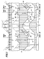
- Figure 1 partially illustrates a knitting loom comprising a plurality of knitting needles 1 slidably mounted in parallel grooves 2 of a needle bed 3.
- the needles of the tray (not shown) are mounted in radial grooves.
- the needles 1 comprise, in this example, a fixed heel 4 engaged with a first cam track 5 and a rocker 6 mounted oscillating in a cutout 7 formed in the stem of the needle 1.
- the bottom of this cutout 7 is flat while the two sides 7a, 7b adjacent to this bottom are formed by arcs of a circle whose center is substantially set back from the bottom of this cutout 7.
- the rocker 6 has on its edge two sides 6a, 6b which form an obtuse angle between them, and are respectively adjacent to two arcs of circles 6c, 6d which have the same center and the same radius as the sides 7a, 7b of the cutout 7.
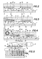
- This rocker 6 has two shaped heels 8 and 9 of rectangular trapezium, the end face of which connects the two parallel and unequal sides is in the extension of the part of the needle rod 1 in which the cutout 7 is formed, when this heel is retracted in this cutout 7.
- heel 8 or 9 When heel 8 or 9 is in its position taken out of the cutting 7 its parallel and unequal edges are perpendicular to the longitudinal axis of the needle 1.
- the movement of the rocker 6 from one to the other of its limit positions s ' accompanies a longitudinal movement of the heels 8 and 9. This feature is very important, insofar as it allows in particular to perform the self-locking of the rocker, as will be explained later.
- the selection member is constituted by a thin rod 10 slidably mounted through a cam 22 and whose free end is capable of projecting out of the profile of this cam 22.
- the other end of this rod 10 is fixed to an electrical conductor 12 disposed between the two poles of a permanent magnet 13.
- This electrical conductor 12 is preferably constituted by a strip of copper or aluminum whose width of the rectangular section is placed in the plane of the air gap of the permanent magnet 13 in order to make the conductor more rigid in this plane.
- this conductor is welded to ribbons 14 and 15 of CuAg forming elbows and whose sections are rotated by 90 ° relative to that of the conductive ribbon 12 to make them flexible in the plane of the air gap.
- the ends of this conductor 12, 14, 15 are anchored to terminals 18 and 19 connected to the secondary of a transformer 16 whose primary is connected to a current pulse source 17.
- the product ⁇ d ⁇ 1,8.10 ⁇ 4 whereas in the case of aluminum this same product ⁇ dr 0,73.10 ⁇ 4. It is therefore possible for the same movement of the rod 10 to reduce the pulse duration and therefore to increase the frequency.
- the magnetic induction can also be brought to 0.8 Tesla and the current pulses can be 10A.
- the end faces 8a of the trapezoidal heels 8 are bevelled, so that when the end of the rod 10 is advanced in the trajectory of the heels 8, the lower edge of these faces bevelled 8a meets the rod 10, and when moving in the direction of the arrow F1 this bevel acts on the rocker 6 like a cam which causes a slight displacement of this rocker 6 in the position illustrated by FIG. 4.
- Figures 1 and 2 show that the initial mechanism sation of the selection which has just been described in detail is associated with two cams 22 and 23 which are arranged on either side of the respective trajectories of the heels 8, 9 of the rockers 6.
- the cam 22 comprises two substantially parallel profiles, one 24 lower and the other 25 upper.
- the cam 23 has a profile 26 whose role will be explained later.
- the actuating rod 10 of the selection initialization mechanism is movable between two positions, one in which it projects from the cam profile 25 to be in the trajectory of the heels 8 which then protrude from the cutouts 7 of the needles 1.
- This selection initialization mechanism is preceded by a fixed cam 27 (FIGS. 1 and 2) disposed in the trajectory of the heels 9 in the out position of the cutouts 7.
- Figure 1 is supplemented by greenhouse cams 28, capable of moving in a back and forth movement in the direction of the double arrow F2. Note also that following the actuating rod 10, the bored cam 25 has a recess 25a to allow the heels 8 to tilt in the cutout 7.
- the parallel faces of the trapezoidal profile of the heel 8 are perpendicular to the longitudinal axis of the needle 1.
- this cam 22 controls the movement of the needles 1 in the knitting position with a positive guidance of the needles when going up or down.
- each needle 1 will comprise two rockers 6 each actuated by an actuating rod 10.
- each rocker always having one of its two heels, we manage to make three different combinations.
- a form of execution of this kind will be described subsequently in relation to a rectilinear trade. The transposition to the circular profession is obvious to the skilled person.
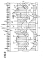
- the variant of FIG. 6 relates to the adaptation of the selection device described in relation to FIGS. 1 to 6 to a straight loom. Given that in such a profession the needle bearing needle bed is fixed and that it is the cam carriage which moves alternately in both directions, the profile of these cams must be symmetrical with respect to the member. Selection.
- This variant the operation of which is also identical to the embodiment of FIG. 1, will not be described again in its entirety, it will be limited to the only modifications necessary for the adaptation of this device to the rectilinear loom. In fact the actual selection mechanism remains unchanged, it is essentially the cam profiles which undergo modifications in relation to the felling or greenhouse cam. These cams 28, acting when the carriage which carries them moves from left to right (arrow F4) must be mounted retractable relative to the heels 8.
- a second set of 28 ⁇ greenhouse or felling cams drawn in phantom lines are intended to come into the trajectory of the heels 8 by a movement perpendicular to the paln of the design when the carriage which carries these cams moves from right to left.
- the respective cam profiles 5 and 25 must have an infection with respect to these greenhouse cams 28 ⁇ as they have with respect to cams 28.
- a second set of cams 27 ⁇ is intended to actuate the heels 9 which have come out , when the carriage moves in the opposite direction to that of arrow F4.
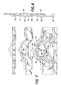
- Figures 7 to 10 The embodiment illustrated in Figures 7 to 10 is illustrated more schematically than the previous embodiment.
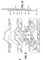
- the various cams have been shown in different thicker dashed lines, the trajectory of each of the projecting heels of the guide groove, the trajectory of the other heels, retracted in this groove being drawn in thinner mixed lines.
- Figures 8 and 10 show in profile the positions of the scales corresponding to the paths illustrated in Figures 7 and 9 respectively.
- the mechanisms for selecting the position of the needles have no longer been shown since they may be similar to those which have been described previously.
- a needle 31 comprising a fixed heel 32 and four movable heels 33, 34, 35 and 36 integral two by two with two rockers 37 and 38 mounted oscillating in two cutouts 39 and 40.
- rockers are similar to the flip-flop 6 in FIG. 1 so that we will not return here to their particularities and their operation, the reader being able to refer to the detailed description made about them in relation to the first embodiment.
- the trajectories of the three heels 32, 34 and 36 which project from the guide groove of the needle 31 have been drawn in thicker lines.
- the trajectories of the other two heels 33 and 35 are drawn in thin mixed lines.
- three heels necessarily protrude from the guide groove of the needle 31 and engage with the cams, the positive guidance of this needle actually uses two heels. In the displacement of the needle in the mesh position illustrated by FIG. 7, it is the heels 32 and 36 which carry out the guidance in the closed cam path.
- the other two knitting positions are the stitch picking position, which consists in bringing out the heels 34 and 35 by retracting the heel 36. In this case, it is these two heels whose lower edge edges respectively engage with the profile 55 respectively 54 of the cam 44 which effect the positive control of the needle.
- the upward movement is effected by acting on the face of lower edge of the heel 34 creating a torque tending to keep the opposite arm carrying the heel 34 against the bottom of the cutout 39 while the downward movement creates a torque in the other direction by acting on the upper edge face of the heel 35 of the rocker 38, creating a torque tending to keep the arm carrying the heel 36 in abutment against the bottom of the cutout 40.
- the non-knitting position is carried out with the heels 32, 33 and 35 projecting out of the guide groove, the needle being guided by the upper and lower edge faces of the heels 33 respectively 32.
- FIG. 9 illustrates the position of the cams for carrying out a mesh transfer of the needles from one needle bed to another.
- the sliding cams 46 and 47 are lowered alternately and the cams 48 and 49 are brought to the plane of the other cams.
- the cam 45 is retracted and half of the cam 42.
- FIG. 10 shows the position of the rockers 37 and 38 with the heels 33 and 36 in the projecting position outside the guide groove. In this case the needle is guided by the heels 32 and 36. It can be seen that during the descent of the needle there is an instant when the needle is not guided positively, but it is not a question here of l 'one of the three knitting positions, which is of no consequence.
- the rocker 38 is actuated by the upper edge face of the heel 36, which tends to move the rocker 38 in its other stable position.
- the heel 35 of the rocker 38 is located behind the cam 44 which prevents this tilting.
- the other transfer position corresponding to the needle bed which receives the transferred meshes according to the operation illustrated in FIGS. 9 and 10 consists in keeping the cams in the same position and bringing out the heels 33 and 35, the needle then being guided by the sole heel 35, but again this is not a knitting operation here and the positive guiding of the needle in this case does not correspond to a necessity.
Landscapes
- Engineering & Computer Science (AREA)
- Textile Engineering (AREA)
- Knitting Machines (AREA)
Applications Claiming Priority (2)
| Application Number | Priority Date | Filing Date | Title |
|---|---|---|---|
| CH840/87A CH670464A5 (de) | 1987-03-06 | 1987-03-06 | |
| CH840/87 | 1987-03-06 |
Publications (2)
| Publication Number | Publication Date |
|---|---|
| EP0285553A1 true EP0285553A1 (de) | 1988-10-05 |
| EP0285553B1 EP0285553B1 (de) | 1991-12-18 |
Family
ID=4196430
Family Applications (1)
| Application Number | Title | Priority Date | Filing Date |
|---|---|---|---|
| EP88810110A Expired - Lifetime EP0285553B1 (de) | 1987-03-06 | 1988-02-23 | Steuervorrichtung für die Strickstellung der Nadeln an einer Strickmaschine |
Country Status (6)
| Country | Link |
|---|---|
| US (1) | US4827740A (de) |
| EP (1) | EP0285553B1 (de) |
| JP (1) | JP2721674B2 (de) |
| CH (1) | CH670464A5 (de) |
| DE (1) | DE3866915D1 (de) |
| ES (1) | ES2029728T3 (de) |
Families Citing this family (9)
| Publication number | Priority date | Publication date | Assignee | Title |
|---|---|---|---|---|
| DE4007253A1 (de) * | 1990-03-08 | 1991-09-12 | Sipra Patent Beteiligung | Strickmaschine |
| CZ280577B6 (cs) * | 1991-12-30 | 1996-02-14 | Uniplet, A.S. | Okrouhlý pletací stroj |
| US5568738A (en) * | 1995-11-28 | 1996-10-29 | Pai Lung Machinery Mill Co., Ltd. | Needle selection device of a circular knitting machine |
| DE19822862C2 (de) * | 1998-05-22 | 2001-05-17 | Sipra Patent Beteiligung | Strickmaschinennadel und damit ausgerüstete Strickmaschine |
| DE19822861C2 (de) * | 1998-05-22 | 2001-05-17 | Sipra Patent Beteiligung | Platine für eine Rundstrickmaschine und dafür geeignete Auswähleinrichtung |
| DE10111930C2 (de) * | 2001-03-13 | 2003-02-27 | Groz Beckert Kg | Systemteil |
| CN101629355B (zh) | 2009-05-31 | 2012-05-23 | 冯加林 | 一种织针组合 |
| HUE035114T2 (en) * | 2010-05-04 | 2018-05-02 | Steps Holding Bv | Circular knitting machine and method for producing knitted article with circular knitting machine |
| IT202100025898A1 (it) * | 2021-10-08 | 2023-04-08 | Santoni & C Spa | Catena di trasmissione per organi di formazione maglia di una macchina circolare per maglieria e macchina circolare per maglieria comprendente tale catena di trasmissione |
Citations (4)
| Publication number | Priority date | Publication date | Assignee | Title |
|---|---|---|---|---|
| DE2008822A1 (de) * | 1969-02-25 | 1970-10-01 | The Bentley Machine Development Company Ltd., Leicester (Großbritannien) | Nadelsteuereinrichtung für Wirk- oder Strickmaschinen |
| DE2024370A1 (de) * | 1969-05-19 | 1970-11-26 | The Warner & Swasey Company, Cleveland, Ohio (V.St.A.) | Strickmaschine |
| US3779042A (en) * | 1971-10-14 | 1973-12-18 | Singer Co | Circular knitting machines for producing a patterned fabric |
| GB2173220A (en) * | 1985-04-01 | 1986-10-08 | Textima Veb K | Multisystem circular knitting machine |
Family Cites Families (9)
| Publication number | Priority date | Publication date | Assignee | Title |
|---|---|---|---|---|
| CH389813A (fr) * | 1962-07-11 | 1965-03-31 | Beguin Rene | Procédé pour la sélection des aiguilles d'une machine à tricoter et dispositif pour la mise en oeuvre de ce procédé |
| DE1804350A1 (de) * | 1967-10-24 | 1970-05-14 | Lebocey & Cie Georges | Verfahren und Vorrichtung zum Auswaehlen der Stricknadeln oder der Strickhilfsmittel auf Strickmaschinen und mit dieser Vorrichtung versehene Strickmaschine |
| FR1594994A (de) * | 1968-12-10 | 1970-06-08 | ||
| ZA697680B (en) * | 1969-10-31 | 1971-01-27 | Gkn Mills Ltd | Apparatus suitable for use in the moulding of concrete |
| DE2010973C3 (de) * | 1970-03-09 | 1982-05-27 | H. Stoll Gmbh & Co, 7410 Reutlingen | Strickmaschine, insbesondere Flachstrickmaschine |
| DE2315334A1 (de) * | 1973-03-28 | 1974-10-10 | Stoll & Co H | Strickmaschine, insbesondere flachstrickmaschine |
| DE2412497A1 (de) * | 1974-03-15 | 1975-09-18 | Singer Alemannia Maschf | Elektromagnetisch-mechanische nadelauswahl-einrichtung fuer strickmaschinen |
| DE3406870C2 (de) * | 1984-02-25 | 1986-06-12 | H. Stoll Gmbh & Co, 7410 Reutlingen | Flachstrickmaschine mit elektromechanischer Auswahl |
| DE3407965A1 (de) * | 1984-03-03 | 1985-09-05 | E.G.O. Elektro-Geräte Blanc u. Fischer, 7519 Oberderdingen | Grillplatte |
-
1987
- 1987-03-06 CH CH840/87A patent/CH670464A5/fr not_active IP Right Cessation
-
1988
- 1988-02-23 EP EP88810110A patent/EP0285553B1/de not_active Expired - Lifetime
- 1988-02-23 ES ES198888810110T patent/ES2029728T3/es not_active Expired - Lifetime
- 1988-02-23 DE DE8888810110T patent/DE3866915D1/de not_active Expired - Fee Related
- 1988-03-03 US US07/163,543 patent/US4827740A/en not_active Expired - Lifetime
- 1988-03-04 JP JP63049911A patent/JP2721674B2/ja not_active Expired - Lifetime
Patent Citations (4)
| Publication number | Priority date | Publication date | Assignee | Title |
|---|---|---|---|---|
| DE2008822A1 (de) * | 1969-02-25 | 1970-10-01 | The Bentley Machine Development Company Ltd., Leicester (Großbritannien) | Nadelsteuereinrichtung für Wirk- oder Strickmaschinen |
| DE2024370A1 (de) * | 1969-05-19 | 1970-11-26 | The Warner & Swasey Company, Cleveland, Ohio (V.St.A.) | Strickmaschine |
| US3779042A (en) * | 1971-10-14 | 1973-12-18 | Singer Co | Circular knitting machines for producing a patterned fabric |
| GB2173220A (en) * | 1985-04-01 | 1986-10-08 | Textima Veb K | Multisystem circular knitting machine |
Also Published As
| Publication number | Publication date |
|---|---|
| US4827740A (en) | 1989-05-09 |
| JPS63227843A (ja) | 1988-09-22 |
| EP0285553B1 (de) | 1991-12-18 |
| DE3866915D1 (de) | 1992-01-30 |
| CH670464A5 (de) | 1989-06-15 |
| ES2029728T3 (es) | 1992-09-01 |
| JP2721674B2 (ja) | 1998-03-04 |
Similar Documents
| Publication | Publication Date | Title |
|---|---|---|
| EP0108700B1 (de) | Fachbildungsvorrichtung mit Nadelwahl | |
| EP0285553B1 (de) | Steuervorrichtung für die Strickstellung der Nadeln an einer Strickmaschine | |
| FR2585042A1 (fr) | Metier a tricoter rectiligne equipe d'aiguilles articulees | |
| EP0161010B1 (de) | Verfahren und Vorrichtung zum Vereinzeln flexibler Flächengebilde, insbesondere Textilwaren und Maschine zum Vereinzeln und zur Führung dieser Flächengebilde | |
| MC1319A1 (fr) | Systeme de commande de levee de fils de chaine d'un metier a tisser | |
| EP0189602B1 (de) | Strickmaschine | |
| EP0131481B1 (de) | Mischwechsler für Webmaschinen | |
| FR2491961A1 (fr) | Mecanique d'armure a commande par poulies | |
| FR2736659A1 (fr) | Dispositif pour la selection de crochets dans une mecanique d'armure de metier a tisser | |
| EP0266286A2 (de) | Vorrichtung zum Schusseintrag bei schützenlosen Webmaschinen | |
| EP0051548B1 (de) | Platine für Schaftmaschine und dgl. | |
| FR2751352A1 (fr) | Dispositif pour effectuer la jonction entre un fil en cours de tricotage et un fil selectionne a tricoter destine a une machine a tricoter | |
| FR2524015A1 (fr) | Dispositif pour inserer des fils de chaine dans des lices a tisser et lamelles appretees | |
| WO1998018987A1 (fr) | Dispositif de selection de fils de trame pour un metier a tisser | |
| FR1465610A (fr) | Perfectionnements apportés aux sélecteurs de trame pour métiers à tisser sans navette | |
| FR2513668A1 (fr) | Metier a tricoter | |
| EP0043778A1 (de) | Verfahren und Anordnung zum Vorlöten von Lötkugeln auf Kontaktfahnen | |
| BE541343A (de) | ||
| EP0119122B1 (de) | Vorrichtung zum Übertragen des Schussfadens an der Eintragsnadel einer Webmaschine und mit einer solchen Vorrichtung versehene Webmaschine | |
| EP0338909A1 (de) | Werkstückzuführung zu einer Nähmaschine | |
| FR2675826A1 (fr) | Dispositif pour former la foule dans un metier a tisser. | |
| FR2491509A1 (fr) | Tricoteuse manuelle | |
| FR2735796A1 (fr) | Metier a tisser le velours faconne de soierie | |
| CH321477A (fr) | Métier à tisser sans navette | |
| BE391838A (de) |
Legal Events
| Date | Code | Title | Description |
|---|---|---|---|
| PUAI | Public reference made under article 153(3) epc to a published international application that has entered the european phase |
Free format text: ORIGINAL CODE: 0009012 |
|
| AK | Designated contracting states |
Kind code of ref document: A1 Designated state(s): CH DE ES GB IT LI |
|
| 17P | Request for examination filed |
Effective date: 19890311 |
|
| RAP1 | Party data changed (applicant data changed or rights of an application transferred) |
Owner name: SIPRA PATENTENTWICKLUNGS- UND BETEILIGUNGSGESELLSC |
|
| 17Q | First examination report despatched |
Effective date: 19910219 |
|
| GRAA | (expected) grant |
Free format text: ORIGINAL CODE: 0009210 |
|
| AK | Designated contracting states |
Kind code of ref document: B1 Designated state(s): CH DE ES GB IT LI |
|
| REF | Corresponds to: |
Ref document number: 3866915 Country of ref document: DE Date of ref document: 19920130 |
|
| GBT | Gb: translation of ep patent filed (gb section 77(6)(a)/1977) | ||
| ITF | It: translation for a ep patent filed | ||
| REG | Reference to a national code |
Ref country code: ES Ref legal event code: FG2A Ref document number: 2029728 Country of ref document: ES Kind code of ref document: T3 |
|
| PLBE | No opposition filed within time limit |
Free format text: ORIGINAL CODE: 0009261 |
|
| STAA | Information on the status of an ep patent application or granted ep patent |
Free format text: STATUS: NO OPPOSITION FILED WITHIN TIME LIMIT |
|
| 26N | No opposition filed | ||
| REG | Reference to a national code |
Ref country code: GB Ref legal event code: IF02 |
|
| PGFP | Annual fee paid to national office [announced via postgrant information from national office to epo] |
Ref country code: CH Payment date: 20020130 Year of fee payment: 15 |
|
| PGFP | Annual fee paid to national office [announced via postgrant information from national office to epo] |
Ref country code: ES Payment date: 20020220 Year of fee payment: 15 |
|
| PGFP | Annual fee paid to national office [announced via postgrant information from national office to epo] |
Ref country code: GB Payment date: 20020227 Year of fee payment: 15 |
|
| PGFP | Annual fee paid to national office [announced via postgrant information from national office to epo] |
Ref country code: DE Payment date: 20020307 Year of fee payment: 15 |
|
| PG25 | Lapsed in a contracting state [announced via postgrant information from national office to epo] |
Ref country code: GB Free format text: LAPSE BECAUSE OF NON-PAYMENT OF DUE FEES Effective date: 20030223 |
|
| PG25 | Lapsed in a contracting state [announced via postgrant information from national office to epo] |
Ref country code: ES Free format text: LAPSE BECAUSE OF NON-PAYMENT OF DUE FEES Effective date: 20030224 |
|
| PG25 | Lapsed in a contracting state [announced via postgrant information from national office to epo] |
Ref country code: LI Free format text: LAPSE BECAUSE OF NON-PAYMENT OF DUE FEES Effective date: 20030228 Ref country code: CH Free format text: LAPSE BECAUSE OF NON-PAYMENT OF DUE FEES Effective date: 20030228 |
|
| PG25 | Lapsed in a contracting state [announced via postgrant information from national office to epo] |
Ref country code: DE Free format text: LAPSE BECAUSE OF NON-PAYMENT OF DUE FEES Effective date: 20030902 |
|
| GBPC | Gb: european patent ceased through non-payment of renewal fee | ||
| REG | Reference to a national code |
Ref country code: CH Ref legal event code: PL |
|
| REG | Reference to a national code |
Ref country code: ES Ref legal event code: FD2A Effective date: 20030224 |
|
| PG25 | Lapsed in a contracting state [announced via postgrant information from national office to epo] |
Ref country code: IT Free format text: LAPSE BECAUSE OF NON-PAYMENT OF DUE FEES;WARNING: LAPSES OF ITALIAN PATENTS WITH EFFECTIVE DATE BEFORE 2007 MAY HAVE OCCURRED AT ANY TIME BEFORE 2007. THE CORRECT EFFECTIVE DATE MAY BE DIFFERENT FROM THE ONE RECORDED. Effective date: 20050223 |