EP0285555A1 - Spannvorrichtung eines Werkzeughalters auf einer Spannbasis in einem Bearbeitungszentrum, insbesondere zum Drehen - Google Patents
Spannvorrichtung eines Werkzeughalters auf einer Spannbasis in einem Bearbeitungszentrum, insbesondere zum Drehen Download PDFInfo
- Publication number
- EP0285555A1 EP0285555A1 EP88810129A EP88810129A EP0285555A1 EP 0285555 A1 EP0285555 A1 EP 0285555A1 EP 88810129 A EP88810129 A EP 88810129A EP 88810129 A EP88810129 A EP 88810129A EP 0285555 A1 EP0285555 A1 EP 0285555A1
- Authority
- EP
- European Patent Office
- Prior art keywords
- tool holder
- trihedron
- base
- portions
- conical
- Prior art date
- Legal status (The legal status is an assumption and is not a legal conclusion. Google has not performed a legal analysis and makes no representation as to the accuracy of the status listed.)
- Granted
Links
- 238000005520 cutting process Methods 0.000 title description 2
- 238000003754 machining Methods 0.000 claims description 6
- 230000004913 activation Effects 0.000 claims description 3
- 238000009434 installation Methods 0.000 claims description 3
- 230000003213 activating effect Effects 0.000 claims description 2
- 230000003042 antagnostic effect Effects 0.000 claims description 2
- 238000009826 distribution Methods 0.000 claims description 2
- 238000004140 cleaning Methods 0.000 claims 1
- 239000012530 fluid Substances 0.000 claims 1
- 238000005507 spraying Methods 0.000 claims 1
- 230000003100 immobilizing effect Effects 0.000 abstract 1
- 230000008878 coupling Effects 0.000 description 3
- 238000010168 coupling process Methods 0.000 description 3
- 238000005859 coupling reaction Methods 0.000 description 3
- 238000010586 diagram Methods 0.000 description 2
- 238000003825 pressing Methods 0.000 description 2
- 208000031968 Cadaver Diseases 0.000 description 1
- 208000037656 Respiratory Sounds Diseases 0.000 description 1
- 239000000919 ceramic Substances 0.000 description 1
- 230000000295 complement effect Effects 0.000 description 1
- 239000007788 liquid Substances 0.000 description 1
- 238000004519 manufacturing process Methods 0.000 description 1
- 239000002184 metal Substances 0.000 description 1
- 206010037833 rales Diseases 0.000 description 1
- 230000000717 retained effect Effects 0.000 description 1
- 238000003466 welding Methods 0.000 description 1
Images

Classifications
-
- B—PERFORMING OPERATIONS; TRANSPORTING
- B23—MACHINE TOOLS; METAL-WORKING NOT OTHERWISE PROVIDED FOR
- B23Q—DETAILS, COMPONENTS, OR ACCESSORIES FOR MACHINE TOOLS, e.g. ARRANGEMENTS FOR COPYING OR CONTROLLING; MACHINE TOOLS IN GENERAL CHARACTERISED BY THE CONSTRUCTION OF PARTICULAR DETAILS OR COMPONENTS; COMBINATIONS OR ASSOCIATIONS OF METAL-WORKING MACHINES, NOT DIRECTED TO A PARTICULAR RESULT
- B23Q3/00—Devices holding, supporting, or positioning work or tools, of a kind normally removable from the machine
- B23Q3/18—Devices holding, supporting, or positioning work or tools, of a kind normally removable from the machine for positioning only
-
- B—PERFORMING OPERATIONS; TRANSPORTING
- B23—MACHINE TOOLS; METAL-WORKING NOT OTHERWISE PROVIDED FOR
- B23B—TURNING; BORING
- B23B29/00—Holders for non-rotary cutting tools; Boring bars or boring heads; Accessories for tool holders
- B23B29/04—Tool holders for a single cutting tool
-
- B—PERFORMING OPERATIONS; TRANSPORTING
- B23—MACHINE TOOLS; METAL-WORKING NOT OTHERWISE PROVIDED FOR
- B23Q—DETAILS, COMPONENTS, OR ACCESSORIES FOR MACHINE TOOLS, e.g. ARRANGEMENTS FOR COPYING OR CONTROLLING; MACHINE TOOLS IN GENERAL CHARACTERISED BY THE CONSTRUCTION OF PARTICULAR DETAILS OR COMPONENTS; COMBINATIONS OR ASSOCIATIONS OF METAL-WORKING MACHINES, NOT DIRECTED TO A PARTICULAR RESULT
- B23Q1/00—Members which are comprised in the general build-up of a form of machine, particularly relatively large fixed members
- B23Q1/0063—Connecting non-slidable parts of machine tools to each other
-
- Y—GENERAL TAGGING OF NEW TECHNOLOGICAL DEVELOPMENTS; GENERAL TAGGING OF CROSS-SECTIONAL TECHNOLOGIES SPANNING OVER SEVERAL SECTIONS OF THE IPC; TECHNICAL SUBJECTS COVERED BY FORMER USPC CROSS-REFERENCE ART COLLECTIONS [XRACs] AND DIGESTS
- Y10—TECHNICAL SUBJECTS COVERED BY FORMER USPC
- Y10T—TECHNICAL SUBJECTS COVERED BY FORMER US CLASSIFICATION
- Y10T407/00—Cutters, for shaping
- Y10T407/22—Cutters, for shaping including holder having seat for inserted tool
- Y10T407/227—Cutters, for shaping including holder having seat for inserted tool with separate means to fasten tool seat to holder
-
- Y—GENERAL TAGGING OF NEW TECHNOLOGICAL DEVELOPMENTS; GENERAL TAGGING OF CROSS-SECTIONAL TECHNOLOGIES SPANNING OVER SEVERAL SECTIONS OF THE IPC; TECHNICAL SUBJECTS COVERED BY FORMER USPC CROSS-REFERENCE ART COLLECTIONS [XRACs] AND DIGESTS
- Y10—TECHNICAL SUBJECTS COVERED BY FORMER USPC
- Y10T—TECHNICAL SUBJECTS COVERED BY FORMER US CLASSIFICATION
- Y10T409/00—Gear cutting, milling, or planing
- Y10T409/30—Milling
- Y10T409/309576—Machine frame
- Y10T409/309912—Machine frame including relatively movable components and means to relatively immobilize these components
-
- Y—GENERAL TAGGING OF NEW TECHNOLOGICAL DEVELOPMENTS; GENERAL TAGGING OF CROSS-SECTIONAL TECHNOLOGIES SPANNING OVER SEVERAL SECTIONS OF THE IPC; TECHNICAL SUBJECTS COVERED BY FORMER USPC CROSS-REFERENCE ART COLLECTIONS [XRACs] AND DIGESTS
- Y10—TECHNICAL SUBJECTS COVERED BY FORMER USPC
- Y10T—TECHNICAL SUBJECTS COVERED BY FORMER US CLASSIFICATION
- Y10T82/00—Turning
- Y10T82/25—Lathe
- Y10T82/2585—Tool rest
- Y10T82/2589—Quick release tool or holder clamp
-
- Y—GENERAL TAGGING OF NEW TECHNOLOGICAL DEVELOPMENTS; GENERAL TAGGING OF CROSS-SECTIONAL TECHNOLOGIES SPANNING OVER SEVERAL SECTIONS OF THE IPC; TECHNICAL SUBJECTS COVERED BY FORMER USPC CROSS-REFERENCE ART COLLECTIONS [XRACs] AND DIGESTS
- Y10—TECHNICAL SUBJECTS COVERED BY FORMER USPC
- Y10T—TECHNICAL SUBJECTS COVERED BY FORMER US CLASSIFICATION
- Y10T82/00—Turning
- Y10T82/25—Lathe
- Y10T82/2585—Tool rest
- Y10T82/2591—Tool post
Definitions
- machining centers are currently going in a direction such that one seeks to increase as much as possible the number of machining operations which can be carried out on a part without releasing the latter from its clamp.
- another solution to the problem posed consists in providing a tool fixing base at a suitable location and in equipping the machine with transfer means capable of successively taking tool holders stored in a store and bringing them in and out. fix it automatically on the base so that the corresponding tools are then in the working position.
- the same machine can comprise several fixing bases and this or these bases can be mounted on mobile supports with simple or crossed slides or, if necessary, with axis of rotation.
- the fixing bases can be arranged so as to receive tool holders supporting tools which are themselves movable in rotation, and in this case, the base will comprise a coupling with rotation drive means acting on the tool when the latter is in place.
- prismatic tool holder bases are already known. These bases have several bearing faces and in particular three faces, two of which form a dihedron, while the third, oriented perpendicular to the edge of the dihedron, is a portion of limited surface. which borders a groove formed in one of the faces of the dihedral.
- the body of the tool holder must then have three corresponding faces, which, when put in place, are applied against the faces of the dihedral and against the third stop face.
- this arrangement does not ensure the position of the tool holder relative to the base with sufficient precision having regard to the machining requirements which are currently posed.
- the object of the present invention is therefore to remedy the shortcomings of known devices and to provide a fixing device capable of being actuated in a simple manner and ensuring stable fixing of the tool holder in a position which is predetermined with the maximum of precision.
- the subject of the present invention is a device for fixing a tool holder comprising a rigid body on a tool fixing base, in a machining center, comprising on the fixing base or on the body of the tool holder, portions of support surfaces, fixed, determining a support trihedron and on the other part of the device portions of projecting surfaces intended to bear each against one of said portions of support surface , and means for applying a bearing force on the body of the tool holder, so as to pressing said portions of projecting surfaces against said portions of bearing surfaces, characterized in that said portions of projecting surfaces are convex cap surfaces, the number and distribution of which are chosen so as to immobilize the body of tool holder in a determined position independently of the machining forces and in that the means for applying a pressing force comprise complementary retaining elements associated on the one hand with the body of the tool holder and on the other hand at the base, and an actuating member moving between an inactive position and a locking position when the body of the tool holder is in its working position, then activating the
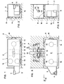
- the tool holder 1 shown in the drawing comprises a prismatic body 2 in the shape of a rectangular parallelepiped provided with an extension 3 on which is fixed, for example by welding, a hard metal or ceramic plate 4.
- the device will therefore be described on the basis of a turning tool, but it is obvious that the body 2 could just as easily serve as a support for other types of tool, including rotary tools, such as drills, or cutters.
- the fixing base 5 is shown diagrammatically, and it can be seen that it has a housing limited by three main planar faces 6, 7 and 8, which form between them an interior tri-rectangle trihedron.
- a housing 9 which can have any suitable shape which will be specified below.
- the faces 6, 7 and 8 will be carefully machined and rectified, at least locally as we will show later. They will be treated so as to present the suitable surface hardness.
- the body 2 of the tool holder has on one of its faces intended to be located opposite the face 8 of the trihedron three spherical caps 14 arranged in a triangle at predetermined locations on the body 2.
- the body 2 On its face located facing the face 7 of the trihedron, the body 2 has two spherical caps 15 which, in a preferred form of the invention are distributed on an axis parallel to the axis of symmetry of the arrangement of the three caps 14.
- a sixth cap 16 is provided on the face of the body 2 which is opposite to the face 6 of the trihedron. This sixth cap is also provided at a predetermined location so as to ensure the stability of the tool holder as will be seen below. It is therefore clear that the only parts of the trihedron to be treated and rectified are located to the right of the caps mentioned above.
- the body of the tool holder comprises a locking arrangement which is constituted by two parallel flanges 17 and 18 which extend across the tool body 2 and are arranged so as to be able to enter the housing 9 of the base.
- These two flanges 17 and 18 are pierced at their central part with cylindrical holes 19 and 20 preferably coaxial in which are engaged locking pins 21 and 22 of cylindrical shape whose length is greater than the thickness of the flanges, and whose outer ends have a conical shape.
- the conical points of the pins 21 and 22 cooperate with the internal faces of two conical housings 23 and 24 which are formed in the sides of the housing 9 of the base.
- the opening angles of the conical tips of the pins 21 and 22 are the same as the opening angles of the conical housings 23 and 24. In a variant, these angles can be the same for each of the two pins 21 and 22 , but in the example of fig. 3 these angles are different. The essential point is however that the common axis of the two housings 23 and 24 is slightly offset from the axis on which the conical points of the two pins 21 and 22 must be when the body 2 is properly supported by its six caps spherical against the faces 6, 7 and 8 of the support trihedron of the base.
- the tool holder bodies with their flanges 17 and 18 and the pins 21 and 22 will therefore be dimensioned and adjusted so that the position of the common axis of the tips of the pins, by ratio at the top of the spherical caps, is exactly adjusted so that, during installation, the offset provided between the respective axes of the conical housings and conical points is achieved.
- the body of the tool holder as a function of the dimensions of the base and to position the spherical caps 14 and 16 so that, taking account of the forces applying to the body of the holder tool during machining, the action line of force F ensures the immobilization and stability of the tool holder.
- This line of action contained in the plane defined by the two axes of the tops of the pins and the tops of the housings will have a predetermined inclination with respect to the planes 7 and 8 of the base.
- a rod 13 is connected for example to a jack (not shown) mounted on the base.
- This rod having at its end two flat wedge-shaped faces 25 and 26, it can be seen that by moving so as to engage these faces 25 and 26 between the rear ends of the pins 21 and 22, it automatically causes the application of the force F.
- the angle of the surfaces 25 and 26 can be adjusted so that the rod is self-wedging, which ensures secure attachment of the tool holder. It suffices when a manipulator brings the tool holder approximately to the position shown in FIG. 3, the pins 21 and 22 being retracted in their holes, and that the actuator actuating the rod 13 is controlled, to achieve the fixing.
- the pins 21 and 22 can be retained in the holes 20 and 19 by balls and spring devices (not shown), or the like.
- the tool holder 27 is also in this case a chisel. Its body 28 has three flat faces 29, 30, 31 which constitute an external tri-rectangle trihedron. It comes to engage, when the tool holder 27 is brought by the manipulator in the vicinity of the base 32, in a housing 33 whose internal faces have projecting spherical caps. Three protruding spherical caps 34 are located in one face of the housing 33 so as to cooperate with the face 29 of the body 27. Two other protruding spherical caps 35 are formed on portions of surfaces of the housing 33 which correspond with the two ends of the face 31.
- the body 28 has in its face 31 in the vicinity of the middle of this face, two projecting flanges 36 and 37 provided with coaxial cylindrical holes 38 and 39 which correspond to holes 20 and 19 of the first embodiment.
- the housing 33 also has, in its end face, a projecting spherical cap 40 which corresponds to the face 30 of the body 28 of the tool holder.
- the jack 41 capable of controlling a rod similar to the rod 13, capable of coming to engage between the flanges 36 and 37.
- Two cylindrical pins with conical heads 43 and 44 are arranged so as to be able to slide in the holes 38 and 39, and are stressed at spacing when the rod of the jack 41 engages between them.
- the retaining means operate in this case as in the first embodiment.
- a housing 42 of the base 32 has opposite planar faces with coaxial and opposite recesses 45 which cooperate with the conical points of the pins 43 and 44, as in the first embodiment.
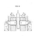
- the diagram in fig. 6 shows the simplified balance sheet of the forces which are at play on the various elements of the retaining device at the time of the action of the jack rod 13.
- the pins exert on the side of the housing in which they are engage a force F1 which is perpendicular to the inclination of the flank of the housing, and has a vertical component F vl (Fig. 6).
- the pins themselves undergo an antagonistic force from the base to the force F vl , which they apply to the flanges of the tool body.
- the forces F vl are greater the smaller the opening angle of the cones of the pin and of the housing.
- the actual forces that the the pins exerted on the tool body are the forces F2 (Fig. 6) constituted by the sum of the forces F vl and the friction forces F f .
- the foce F which applies to the tool body is the sum of the two forces F2.
- the inevitable friction between the cylindrical surface of the pin and the side of the borehole in which it moves will be all the greater as the angle of the point of the pin and that of the housing is more closed. If therefore these angles are more closed on one side of the retainer than on the other, for example on the side turned with reference to FIG. 3 on the side of the face 6, the resulting bearing force F exerted on the tool holder 1 will also have a component directed towards the face 6, so that the spherical cap 16 will be pressed against this face.
- the radius of the spherical caps is determined according to the respective deformations of the tool holder 2 and the base 5 (fig. 1) so that the point of contact of the cap / base is always located inside the surface of the cap. It should be understood that the radius of the spherical cap must be chosen as large as possible and that it can be all the greater as the cooperating parts 2 and 5 are more rigid.
Landscapes
- Engineering & Computer Science (AREA)
- Mechanical Engineering (AREA)
- Cutting Tools, Boring Holders, And Turrets (AREA)
- Jigs For Machine Tools (AREA)
- Gripping On Spindles (AREA)
Applications Claiming Priority (2)
| Application Number | Priority Date | Filing Date | Title |
|---|---|---|---|
| CH861/87 | 1987-03-05 | ||
| CH86187 | 1987-03-05 |
Publications (2)
| Publication Number | Publication Date |
|---|---|
| EP0285555A1 true EP0285555A1 (de) | 1988-10-05 |
| EP0285555B1 EP0285555B1 (de) | 1992-09-16 |
Family
ID=4196894
Family Applications (1)
| Application Number | Title | Priority Date | Filing Date |
|---|---|---|---|
| EP88810129A Expired - Lifetime EP0285555B1 (de) | 1987-03-05 | 1988-03-02 | Spannvorrichtung eines Werkzeughalters auf einer Spannbasis in einem Bearbeitungszentrum, insbesondere zum Drehen |
Country Status (4)
| Country | Link |
|---|---|
| US (1) | US4850255A (de) |
| EP (1) | EP0285555B1 (de) |
| JP (1) | JPS63229204A (de) |
| DE (1) | DE3874584T2 (de) |
Cited By (2)
| Publication number | Priority date | Publication date | Assignee | Title |
|---|---|---|---|---|
| EP0376840A1 (de) * | 1988-12-29 | 1990-07-04 | AEROSPATIALE Société Nationale Industrielle | Vorrichtung zur Befestigung eines zerbrechlichen Gegenstandes, z.B. ein Spiegel |
| EP0455142A3 (en) * | 1990-04-25 | 1992-04-29 | Reko Maschinenbau Gmbh | Profil grinding machine |
Families Citing this family (6)
| Publication number | Priority date | Publication date | Assignee | Title |
|---|---|---|---|---|
| JP2666935B2 (ja) * | 1987-10-30 | 1997-10-22 | 京セラ株式会社 | 切削加工チップ |
| SE463573B (sv) * | 1989-04-24 | 1990-12-10 | Sandvik Ab | Verktyg samt verktygskropp foer brytning av fasta material |
| US5676030A (en) * | 1995-08-14 | 1997-10-14 | Crudgington Machine Tools, Inc. | Multi-spindle CNC lathe |
| US6089148A (en) * | 1999-06-07 | 2000-07-18 | Bloomer; Thomas J | Fixed stroke power press safety stop block |
| US7240593B2 (en) * | 2005-04-19 | 2007-07-10 | Roger Little | Miniature cutting insert holder |
| US8316743B2 (en) * | 2008-11-03 | 2012-11-27 | Fischer Special Tooling | Quick change tool holder |
Citations (2)
| Publication number | Priority date | Publication date | Assignee | Title |
|---|---|---|---|---|
| GB150770A (en) * | 1919-05-07 | 1920-09-07 | Alexander Edward King | Improvements in or relating to adjustable work tables or benches |
| US3175820A (en) * | 1962-11-09 | 1965-03-30 | Portage Machine Company | Rotary table having trimetric adjustment features |
Family Cites Families (15)
| Publication number | Priority date | Publication date | Assignee | Title |
|---|---|---|---|---|
| US2591692A (en) * | 1952-04-08 | Toolholdeb | ||
| US2360567A (en) * | 1942-05-05 | 1944-10-17 | Nicholas P Lloyd | Toolholder |
| US2369904A (en) * | 1943-04-26 | 1945-02-20 | Lulu B Mckee | Lathe |
| US2707419A (en) * | 1953-08-19 | 1955-05-03 | Jergens Tool Specialty Company | Means for locating fixture plates with respect to the beds or platens of machine tools |
| US3130526A (en) * | 1962-05-07 | 1964-04-28 | Cincinnati Milling Machine Co | Mechanism for securing movable machine tool members |
| US3252202A (en) * | 1963-04-30 | 1966-05-24 | Bullard Co | Preset tooling |
| US3466955A (en) * | 1967-05-17 | 1969-09-16 | Carmet Co | Tool holder |
| US3572195A (en) * | 1968-07-22 | 1971-03-23 | Mccrosky Tool Corp | Quick-change toolpost |
| US3694879A (en) * | 1970-09-28 | 1972-10-03 | Kennametal Inc | Tool holder and method of using |
| DE2602096C3 (de) * | 1976-01-21 | 1979-09-27 | Fried. Krupp Huettenwerke Ag, 4630 Bochum | Verbindung aus zwei formschlüssig ineinandergreifenden Teilen, insbesondere zum Befestigen von Schneiden in Drehoder Hobelbänken |
| JPS5438635U (de) * | 1977-08-18 | 1979-03-14 | ||
| JPS6216261Y2 (de) * | 1978-07-21 | 1987-04-24 | ||
| US4390172A (en) * | 1980-11-28 | 1983-06-28 | Presco, Inc. | Precise quick-release positioning mechanism |
| SU1134301A1 (ru) * | 1982-12-22 | 1985-01-15 | Ленинградский Ордена Ленина И Ордена Красного Знамени Механический Институт | Резец |
| US4708040A (en) * | 1987-01-27 | 1987-11-24 | Kennametal Inc. | Lock rod and apparatus for holding a toolholder |
-
1988
- 1988-02-26 US US07/161,150 patent/US4850255A/en not_active Expired - Fee Related
- 1988-03-02 DE DE8888810129T patent/DE3874584T2/de not_active Expired - Fee Related
- 1988-03-02 EP EP88810129A patent/EP0285555B1/de not_active Expired - Lifetime
- 1988-03-04 JP JP63051449A patent/JPS63229204A/ja active Pending
Patent Citations (2)
| Publication number | Priority date | Publication date | Assignee | Title |
|---|---|---|---|---|
| GB150770A (en) * | 1919-05-07 | 1920-09-07 | Alexander Edward King | Improvements in or relating to adjustable work tables or benches |
| US3175820A (en) * | 1962-11-09 | 1965-03-30 | Portage Machine Company | Rotary table having trimetric adjustment features |
Cited By (4)
| Publication number | Priority date | Publication date | Assignee | Title |
|---|---|---|---|---|
| EP0376840A1 (de) * | 1988-12-29 | 1990-07-04 | AEROSPATIALE Société Nationale Industrielle | Vorrichtung zur Befestigung eines zerbrechlichen Gegenstandes, z.B. ein Spiegel |
| FR2641344A1 (fr) * | 1988-12-29 | 1990-07-06 | Aerospatiale | Dispositif de fixation d'un objet fragile tel qu'un miroir |
| US4983028A (en) * | 1988-12-29 | 1991-01-08 | Aeropspatiale Societe Nationale Industrielle | Device for fixing a fragile object, such as mirror |
| EP0455142A3 (en) * | 1990-04-25 | 1992-04-29 | Reko Maschinenbau Gmbh | Profil grinding machine |
Also Published As
| Publication number | Publication date |
|---|---|
| DE3874584D1 (de) | 1992-10-22 |
| EP0285555B1 (de) | 1992-09-16 |
| DE3874584T2 (de) | 1993-03-18 |
| JPS63229204A (ja) | 1988-09-26 |
| US4850255A (en) | 1989-07-25 |
Similar Documents
| Publication | Publication Date | Title |
|---|---|---|
| EP0067766B1 (de) | Bombiereinrichtung eines Werkzeugträgers einer Abkantpresse oder dergleichen | |
| FR2779677A1 (fr) | Appareil manuel a couper les carreaux | |
| EP0285555B1 (de) | Spannvorrichtung eines Werkzeughalters auf einer Spannbasis in einem Bearbeitungszentrum, insbesondere zum Drehen | |
| EP3600736B1 (de) | Spannfutter mit geneigten schiebern | |
| FR2754596A1 (fr) | Guidon reglable pour un fusil d'assaut de la serie m16 a1-a2 -a3 | |
| FR2952898A1 (fr) | Gabarit de positionnement pour la fixation d'une piece d'equipement sur un element de carrosserie d'un vehicule | |
| FR2601609A1 (fr) | Systeme pour l'immobilisation d'une piece reposant sur un support. | |
| FR2547232A1 (fr) | Rectifieuse | |
| EP2500137B1 (de) | Schnellverschlussspindel | |
| EP0245177A1 (de) | Vorrichtung zum Stützen eines Werkstückes zur Ermöglichung der Bearbeitung auf seiner fünften Fläche | |
| WO2020043283A1 (fr) | Pince a tete interchangeable et outil la comportant | |
| EP0262998B1 (de) | Bohrvorrichtung für Holzpaneele und ihr Zusammenbau durch Dübeln | |
| WO2012076767A2 (fr) | Bride de serrage-desserrage | |
| WO2009007572A1 (fr) | Dispositif rotatif de transfert et d'indexation d'objets metalliques, comportant des moyens d'entrainement sans contact | |
| CH688886A5 (fr) | Etau de serrage modulaire. | |
| EP0114443B1 (de) | Werkzeug-Support für Werkzeugmaschine | |
| EP1524054B1 (de) | Spannbackenadapter | |
| EP1331053B1 (de) | Führungsglied für Drehautomat | |
| FR2581338A1 (fr) | Dispositif de changement d'outils pour bras automatique | |
| EP0371890A1 (de) | Magazin zur Lagerung von Werkzeugen und zur Zuführung dieser zu einer Bearbeitungsmaschine | |
| EP0090224A1 (de) | Spannvorrichtung eines Schneideneinsatzes auf einem Werkzeughalter | |
| EP4269815A1 (de) | Werkzeughalter für montagepresse | |
| FR2510918A1 (fr) | Dispositif de poinconnage comportant des moyens de devetissage portes par sa tige de verin et machine poinconneuse equipee de ce dispositif | |
| EP0972609B1 (de) | Haltesystem für eine Werkzeugmaschine | |
| EP1965277B1 (de) | Anker für Uhrhemmungsmechanismus vom Typ Anker und Rad |
Legal Events
| Date | Code | Title | Description |
|---|---|---|---|
| PUAI | Public reference made under article 153(3) epc to a published international application that has entered the european phase |
Free format text: ORIGINAL CODE: 0009012 |
|
| AK | Designated contracting states |
Kind code of ref document: A1 Designated state(s): CH DE FR GB IT LI |
|
| 17P | Request for examination filed |
Effective date: 19881205 |
|
| 17Q | First examination report despatched |
Effective date: 19900126 |
|
| GRAA | (expected) grant |
Free format text: ORIGINAL CODE: 0009210 |
|
| AK | Designated contracting states |
Kind code of ref document: B1 Designated state(s): CH DE FR GB IT LI |
|
| REF | Corresponds to: |
Ref document number: 3874584 Country of ref document: DE Date of ref document: 19921022 |
|
| ITF | It: translation for a ep patent filed | ||
| GBT | Gb: translation of ep patent filed (gb section 77(6)(a)/1977) |
Effective date: 19921215 |
|
| PLBE | No opposition filed within time limit |
Free format text: ORIGINAL CODE: 0009261 |
|
| STAA | Information on the status of an ep patent application or granted ep patent |
Free format text: STATUS: NO OPPOSITION FILED WITHIN TIME LIMIT |
|
| 26N | No opposition filed | ||
| PGFP | Annual fee paid to national office [announced via postgrant information from national office to epo] |
Ref country code: FR Payment date: 19980209 Year of fee payment: 11 |
|
| PGFP | Annual fee paid to national office [announced via postgrant information from national office to epo] |
Ref country code: GB Payment date: 19980220 Year of fee payment: 11 |
|
| PGFP | Annual fee paid to national office [announced via postgrant information from national office to epo] |
Ref country code: DE Payment date: 19980225 Year of fee payment: 11 |
|
| PGFP | Annual fee paid to national office [announced via postgrant information from national office to epo] |
Ref country code: CH Payment date: 19980401 Year of fee payment: 15 |
|
| PG25 | Lapsed in a contracting state [announced via postgrant information from national office to epo] |
Ref country code: GB Free format text: LAPSE BECAUSE OF NON-PAYMENT OF DUE FEES Effective date: 19990302 |
|
| GBPC | Gb: european patent ceased through non-payment of renewal fee |
Effective date: 19990302 |
|
| PG25 | Lapsed in a contracting state [announced via postgrant information from national office to epo] |
Ref country code: FR Free format text: LAPSE BECAUSE OF NON-PAYMENT OF DUE FEES Effective date: 19991130 |
|
| REG | Reference to a national code |
Ref country code: FR Ref legal event code: ST |
|
| PG25 | Lapsed in a contracting state [announced via postgrant information from national office to epo] |
Ref country code: DE Free format text: LAPSE BECAUSE OF NON-PAYMENT OF DUE FEES Effective date: 20000101 |
|
| PG25 | Lapsed in a contracting state [announced via postgrant information from national office to epo] |
Ref country code: LI Free format text: LAPSE BECAUSE OF NON-PAYMENT OF DUE FEES Effective date: 20030331 Ref country code: CH Free format text: LAPSE BECAUSE OF NON-PAYMENT OF DUE FEES Effective date: 20030331 |
|
| REG | Reference to a national code |
Ref country code: CH Ref legal event code: PL |
|
| PG25 | Lapsed in a contracting state [announced via postgrant information from national office to epo] |
Ref country code: IT Free format text: LAPSE BECAUSE OF NON-PAYMENT OF DUE FEES;WARNING: LAPSES OF ITALIAN PATENTS WITH EFFECTIVE DATE BEFORE 2007 MAY HAVE OCCURRED AT ANY TIME BEFORE 2007. THE CORRECT EFFECTIVE DATE MAY BE DIFFERENT FROM THE ONE RECORDED. Effective date: 20050302 |