EP0285575A2 - Dispositif de fixation réglable d'armatures lumineuses dans des faux plafonds - Google Patents
Dispositif de fixation réglable d'armatures lumineuses dans des faux plafonds Download PDFInfo
- Publication number
- EP0285575A2 EP0285575A2 EP88830114A EP88830114A EP0285575A2 EP 0285575 A2 EP0285575 A2 EP 0285575A2 EP 88830114 A EP88830114 A EP 88830114A EP 88830114 A EP88830114 A EP 88830114A EP 0285575 A2 EP0285575 A2 EP 0285575A2
- Authority
- EP
- European Patent Office
- Prior art keywords
- section
- shaped body
- lampholder
- ized
- false
- Prior art date
- Legal status (The legal status is an assumption and is not a legal conclusion. Google has not performed a legal analysis and makes no representation as to the accuracy of the status listed.)
- Withdrawn
Links
Images

Classifications
-
- F—MECHANICAL ENGINEERING; LIGHTING; HEATING; WEAPONS; BLASTING
- F21—LIGHTING
- F21V—FUNCTIONAL FEATURES OR DETAILS OF LIGHTING DEVICES OR SYSTEMS THEREOF; STRUCTURAL COMBINATIONS OF LIGHTING DEVICES WITH OTHER ARTICLES, NOT OTHERWISE PROVIDED FOR
- F21V21/00—Supporting, suspending, or attaching arrangements for lighting devices; Hand grips
- F21V21/02—Wall, ceiling, or floor bases; Fixing pendants or arms to the bases
- F21V21/04—Recessed bases
Definitions
- the present invention relates to a device for adjustably coupling or affixing lighting assemblies to false ceilings, in particular false ceilings of the type consisting of section members and/or panels.
- a problem related to the construction of the mentioned false ceilings is that of coupling or affixing to said false ceilings single lighting assemblies, generally consisting of box-like lampholders, frequently having a very large size, and provided for housing therein one or more fluorescent lamps.
- This lighting assemblies are conventional strictlyly affixed by using rather complex devices which are generally assembled after the assembling of the false ceiling and, accordingly, require a lot of manual labour.
- the task of the present invention is to provide a device for coupling lighting assemblies to false ceilings, of the indicated type, which may be easily and quickly associated to the false ceiling as this latter is constructed, so as to require a very reduced amount of manual labour for the subsequent application of the lampholders to said false ceiling.
- a main object of the present invention is to provide a device for coupling lighting assemblies to the false ceilings of the indicated type, which affords the possibility of affixing said lampholder in an adjustable way, in order to change, as desired, the distance of the lampholder from said false ceiling, within a very broad distance range.
- Another object of the present invention is to provide a device for adjustably coupling lighting assemblies to false ceilings, in particular to false ceilings formed by section members and panels, which comprises a very reduced number of component parts and which, in the meanwhile, affords the possibility of precisely adjusting the distance of the lampholder from the false ceiling.
- Yet another object of the present invention is to provide a coupling device which is adapted to support, in a very reliable way, the single lighting assemblies, at their ends.
- Yet another object of the present invention is to provide such a coupling device which can be easily adapted to all of the fluorescent lampholders which are at present commercially available.
- Yet another object of the present invention is to provide a device for adjustably coupling lighting assemblies to false ceilings, in particular false ceilings of the type formed by section members and metal panels, which has a very reduced cost.
- a device for adjustably coupling lighting assemblies to false ceilings in particular to false ceilings of the type formed by section members and/or metal panels, having the characteristics claimed in claim 1.
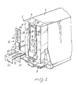
- the adjustable coupling device according to the invention has been herein indicated at the reference number 1, and supports, at one end thereof, a lampholder 2, preferably of the fluorescent lamp type.
- the adjustable coupling device 1 comprises a substantially parallelepipedal box-like body 3, having an open face, which may be snap fitted to the end of the lampholder 2, and an opposite closed face 4.
- two integral ribs 5 and 6 which longitudinally extend along a portion of the height of the face 4 of the half-box shaped body 3.
- the ribs 5 and 6 are provided, at the top thereof, with a substantially rectangular cross-section which is enlarged at the bottom into two opposite portions, thereon there are defined opposite rack portions 7 and 8; each said rack portion is provided with a plurality of teeth having a substantially rectangular cross-section.
- the half-box shaped body 3 is provided with a peripheral edge 9 at the center of which there is defined a substantially rectangular cross-section seat indicated at the reference number 10.
- This seat 10 as shown in figure 1, is provided at a substantially intermediate longitudinal position with respect to the face 4 of the body 3, and the width of the seat 10 substantially corresponds to the transverse distance of the two rack portions 7 and 8.
- the half-box shaped body 3 is provided for association with lamp holder 2 by means of a simple insertion and, if desired, it may be firmly affixed thereto by means of any suitably means, for example by glueing.
- the adjustable coupling device 1 comprises, moreover, as a main part thereof, a preferably metallic small plate, indicated overally at the reference number 11.
- This composite small plate 11 comprises a first flat portion, which substantially vertically extends and has a rectangular shape, being indicated at 12, therewith there is associated, for example by means of welding, a further plate portion 13 of substantially L-shape.
- the L-shape small plate 13 may be affixed to the flat portion 12 by means of any known means: for example by welding to said flat portion 12 a tab portion 14 bent at a right angle and upwardly extending.
- the L-shaped flat portion 13 is welded to the vertically extending flat portion or small plate 12 so as that the greater leg of the L lies in a substantially horizontal plane, and crosses the vertically extending flat portion 12 at a given height.
- the vertically extending flat portion 12 will be divided, from the greater leg of the L, into a lower portion 15 and a top portion 16.
- the flat portion 12, in particular, may be further stabilized by means of a rivet to be inserted into the mentioned slot 19 and hole 20.
- the shorter leg 23 of the L is bent at a right angle and extends substantially downwardly.
- the composite small plate 11 will be directly installed and, to this end, it will be affixed, for example, to an element 24 of the false ceiling, by means of suitable bolt and nut assemblies 25, engaged in an adjustable way in the slots 21 and 22 and coupling the composite plate 11 to the section member 24.
- two half-box shaped bodies 3 will be affixed to the ends of the lampholders 2, and each body 3 will be snap engaged, by means of the cooperation of the teeth of the rack portions 7 and 8 and teeth 17 and 18 of the flat portion 12 so as to affix, at the desired distance from the false ceiling, the lamp holder 2.
- the slot 19 of the vertically extending flat portion 12 will be registered with respect to the hole 20 and, through the slot 19 and hole 20 any suitably permanent affixing means will be introduced, such as, for example, the rivet 26 shown in particular in figure 3.
- Figure 4 shows the lamp-holder 2 fixed to the false ceiling at the two ends thereof, by using two adjustable coupling devices 1 according to the invention.
- the false ceiling consisting of panels P
- the room ceiling S by means of any known means, for example suspending wires F.
- the lampholder 2 may be affixed to the ceiling in a very stable and safe way.
- a further aspect which contributes to improving this coupling is the stabilizing stress of the moment exerted by the weight of the lampholder and each composite plate 11 associated with the coupling devices 1 applied to the ends of said lampholder 2.
Landscapes
- Engineering & Computer Science (AREA)
- General Engineering & Computer Science (AREA)
- Non-Portable Lighting Devices Or Systems Thereof (AREA)
Applications Claiming Priority (2)
| Application Number | Priority Date | Filing Date | Title |
|---|---|---|---|
| IT1995287 | 1987-04-02 | ||
| IT19952/87A IT1203431B (it) | 1987-04-02 | 1987-04-02 | Dispositivo per il fissaggio regolabile di unita' di illuminazione a contro soffitti,in particolare del tipo costituito da profilati e/o da pannelli |
Publications (2)
| Publication Number | Publication Date |
|---|---|
| EP0285575A2 true EP0285575A2 (fr) | 1988-10-05 |
| EP0285575A3 EP0285575A3 (fr) | 1990-01-24 |
Family
ID=11162596
Family Applications (1)
| Application Number | Title | Priority Date | Filing Date |
|---|---|---|---|
| EP88830114A Withdrawn EP0285575A3 (fr) | 1987-04-02 | 1988-03-23 | Dispositif de fixation réglable d'armatures lumineuses dans des faux plafonds |
Country Status (2)
| Country | Link |
|---|---|
| EP (1) | EP0285575A3 (fr) |
| IT (1) | IT1203431B (fr) |
Family Cites Families (8)
| Publication number | Priority date | Publication date | Assignee | Title |
|---|---|---|---|---|
| US3004141A (en) * | 1957-12-16 | 1961-10-10 | Reynolds Metals Co | Sheet metal panel type ceiling construction |
| NL6706004A (fr) * | 1967-04-28 | 1968-10-29 | ||
| DE2102444C3 (de) * | 1971-01-20 | 1975-01-23 | Trilux-Lenze Kg, 5760 Neheimhuesten | Vorrichtung zum Befestigen von Leuchtengehäusen |
| DE2318195C3 (de) * | 1973-04-11 | 1975-12-04 | Trilux-Lenze Kg, 5760 Neheim-Huesten | Vorrichtung zur Befestigung von Deckeneinbauleuchten |
| FR2238117A1 (en) * | 1973-07-20 | 1975-02-14 | Erco Leuchten | Electric light fitting for suspended ceiling - has two electric couplings, component box, lamp fittings, and lamp housing |
| AT377068B (de) * | 1978-01-20 | 1985-02-11 | Trilux Lenze Gmbh & Co Kg | Befestigungsvorrichtung fuer eine deckeneinbau-leuchte |
| DE2915545C2 (de) * | 1979-04-18 | 1983-12-08 | Trilux-Lenze Gmbh + Co Kg, 5760 Arnsberg | Vorrichtung zur Befestigung einer Deckeneinbauleuchte mit einem nach außen deckenparallel abgesetzten Befestigungsrand an Deckenträgern |
| SE455225B (sv) * | 1985-05-23 | 1988-06-27 | Ecophon Ab | Festanordning for upphengning av ett foremal sasom en belysningsarmatur |
-
1987
- 1987-04-02 IT IT19952/87A patent/IT1203431B/it active
-
1988
- 1988-03-23 EP EP88830114A patent/EP0285575A3/fr not_active Withdrawn
Also Published As
| Publication number | Publication date |
|---|---|
| EP0285575A3 (fr) | 1990-01-24 |
| IT8719952A0 (it) | 1987-04-02 |
| IT1203431B (it) | 1989-02-15 |
Similar Documents
| Publication | Publication Date | Title |
|---|---|---|
| US4723749A (en) | Channel clip | |
| JPH0628908A (ja) | 照明設備及びその製造方法 | |
| EP2951366B1 (fr) | Agrafe pour boiserie périmétrique | |
| US3948473A (en) | Universal cable rack | |
| US4494346A (en) | Ceiling system and panel-securing device therefor | |
| EP0285575A2 (fr) | Dispositif de fixation réglable d'armatures lumineuses dans des faux plafonds | |
| US4723199A (en) | Tubular electric lamp fixture | |
| JPH0317373Y2 (fr) | ||
| JPH097418A (ja) | 埋込形照明器具システム及び埋込形照明器具 | |
| JPS6282603A (ja) | ランプ支持装置 | |
| JPH03675Y2 (fr) | ||
| JPS6237844Y2 (fr) | ||
| JPS6211464Y2 (fr) | ||
| JPH0427052Y2 (fr) | ||
| JPS621685Y2 (fr) | ||
| JPH077602B2 (ja) | 照明器具用ルーバ | |
| JPH0622019Y2 (ja) | 天井下地パネル取り付け金物 | |
| JPS5935927Y2 (ja) | 白熱灯用ソケツト台 | |
| JPS6217925Y2 (fr) | ||
| JPS5855526Y2 (ja) | 照明器具のル−バ固定装置 | |
| JPH0620820Y2 (ja) | 格子状パネル | |
| JP2856334B2 (ja) | システム天井用照明器具の取付脚 | |
| JP2549312Y2 (ja) | 照明器具用枠支持装置 | |
| JPH0541455Y2 (fr) | ||
| JPS5853372Y2 (ja) | 天井下地材吊持連結金具 |
Legal Events
| Date | Code | Title | Description |
|---|---|---|---|
| PUAI | Public reference made under article 153(3) epc to a published international application that has entered the european phase |
Free format text: ORIGINAL CODE: 0009012 |
|
| AK | Designated contracting states |
Kind code of ref document: A2 Designated state(s): BE CH DE ES FR GB GR LI NL |
|
| PUAL | Search report despatched |
Free format text: ORIGINAL CODE: 0009013 |
|
| AK | Designated contracting states |
Kind code of ref document: A3 Designated state(s): BE CH DE ES FR GB GR LI NL |
|
| 17P | Request for examination filed |
Effective date: 19900515 |
|
| 17Q | First examination report despatched |
Effective date: 19930323 |
|
| STAA | Information on the status of an ep patent application or granted ep patent |
Free format text: STATUS: THE APPLICATION HAS BEEN WITHDRAWN |
|
| 18W | Application withdrawn |
Withdrawal date: 19930602 |