EP0285712B1 - Charnière dégondable - Google Patents
Charnière dégondable Download PDFInfo
- Publication number
- EP0285712B1 EP0285712B1 EP19870302968 EP87302968A EP0285712B1 EP 0285712 B1 EP0285712 B1 EP 0285712B1 EP 19870302968 EP19870302968 EP 19870302968 EP 87302968 A EP87302968 A EP 87302968A EP 0285712 B1 EP0285712 B1 EP 0285712B1
- Authority
- EP
- European Patent Office
- Prior art keywords
- hinge
- collar
- leaf
- pin
- assembly according
- Prior art date
- Legal status (The legal status is an assumption and is not a legal conclusion. Google has not performed a legal analysis and makes no representation as to the accuracy of the status listed.)
- Expired
Links
- 230000006835 compression Effects 0.000 claims description 13
- 238000007906 compression Methods 0.000 claims description 13
- 239000002184 metal Substances 0.000 claims description 5
- 230000000295 complement effect Effects 0.000 claims description 3
- 239000012858 resilient material Substances 0.000 claims description 2
- 238000000926 separation method Methods 0.000 description 4
- 230000037431 insertion Effects 0.000 description 2
- 238000003780 insertion Methods 0.000 description 2
- 230000000712 assembly Effects 0.000 description 1
- 238000000429 assembly Methods 0.000 description 1
- 230000004323 axial length Effects 0.000 description 1
- 238000010276 construction Methods 0.000 description 1
- 230000001419 dependent effect Effects 0.000 description 1
- 239000000463 material Substances 0.000 description 1
- 230000002093 peripheral effect Effects 0.000 description 1
- 239000004033 plastic Substances 0.000 description 1
- 229920003023 plastic Polymers 0.000 description 1
- -1 polytetrafluoroethylene Polymers 0.000 description 1
- 229920001343 polytetrafluoroethylene Polymers 0.000 description 1
- 239000004810 polytetrafluoroethylene Substances 0.000 description 1
- 238000003466 welding Methods 0.000 description 1
Images

Classifications
-
- E—FIXED CONSTRUCTIONS
- E05—LOCKS; KEYS; WINDOW OR DOOR FITTINGS; SAFES
- E05D—HINGES OR SUSPENSION DEVICES FOR DOORS, WINDOWS OR WINGS
- E05D7/00—Hinges or pivots of special construction
- E05D7/10—Hinges or pivots of special construction to allow easy separation or connection of the parts at the hinge axis
- E05D7/1044—Hinges or pivots of special construction to allow easy separation or connection of the parts at the hinge axis in an axial direction
- E05D7/105—Hinges or pivots of special construction to allow easy separation or connection of the parts at the hinge axis in an axial direction requiring a specific angular position
Definitions
- the present invention relates to a lift-off hinge assembly, particularly for use in hingedly connecting a vehicle door to a vehicle body.
- a lift-off hinge assembly including a first hinge leaf hingedly connected to a second hinge leaf by a hinge pin rotatably located in one hinge leaf, the hinge pin having a bearing portion upon which the other hinge leaf is seated and being connected to the other hinge leaf by a removable axially compressible collar.
- the collar is located in the hinge eye of the other hinge leaf and is compressed towards the bearing portion to place the collar under axial compression so that it rotatably locks the hinge pin and the other hinge leaf together.
- a lift-off hinge assembly including a first hinge leaf hingedly connected to a second hinge leaf by a hinge pin rotatably located in one hinge leaf, the hinge pin having a bearing portion upon which the other hinged leaf is seated and being connected to the other hinge leaf by a removable axially compressible collar which is located at least in part within the hinge eye of said other hinge leaf and compression means arranged to urge the collar towards the bearing portion to place the collar under axial compression so that it rotatably locks the hinge pin and other hinge leaf together, characterised in that the collar is of frusto-conical shape and the hinge eye includes an inclined surface portion complementary to the inclined surface of the collar, the hinge pin having a head portion including a connection portion having a diameter less than the minimum diameter of the hinge eye, the collar having an internal axially extending bore in which the connection portion is received, the collar on axial compression being moved toward said bearing portion to cause the collar to wedgingly locate between the connection portion and inclined surface portion and thereby
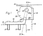
- the hinge assembly 10 includes a hinge leaf 12 which is hingedly connected to hinge leaf 14 by means of a hinge pin 16.
- leaf 12 is intended to be secured to a vehicle door 15 say by welding and leaf 14 is intended to be secured to the vehicle body 13 by means of bolts 17.
- the hinge pin 16 has a constant diameter portion 18 which is rotatably received in a bush 20 located in a bore 22 formed in support arm 14 a of leaf 14.
- the bush 20 is conveniently formed from a suitable plastics material such as polytetrafluoroethylene, which may be reinforced for instance with a metal mesh.
- the pin portion 18 forms the majority of the length of pin 16 and provides a large rotative surface area for rotatably supporting large loads.
- the pin 16 is provided with a head portion of relatively short axial extent.
- the head portion includes a connection portion 26 and a bearing portion 27.
- the connection portion 26 is slidingly received in an aperture 26 a formed in a support arm 28 which forms part of leaf 12.
- the support arm 28 bears upon the bearing portion 27 which in turn bears upon support arm 14 a via an annular flange 30 of bush 20.
- the upper portion of support arm 14 a is provided with a projection 34 which is spaced from the upper edge 14 b of the support arm 14 a to form a groove 14 c .
- the support arm 28 has an arcuate portion 32 which is arranged to pass through the groove 14 c during relative angular movement of the hinge leaves about their hinge axes.
- the arcuate portion 32 terminates at a radially inwardly directed shoulder 36.
- the support arm 28 has an arcuate portion 32 which terminates at a radially outwardly located shoulder 42.
- the arcuate portion is provided with a recess 46 of sufficient dimensions to enable the projection 34 to pass therethrough on withdrawal of support arm 28 from the head portion of the pin.
- the position of the recess 46 along the length of arcuate portion 32 determines the relative angular position of leaves 12, 14 at which separation of the leaves can be effected. In use, this position is normally chosen to enable the door to be lifted at a position whereat it is less likely to interfere with the vehicle body whilst being lifted to separate the hinge leaves.
- At least leaf 12 is conveniently made from metal sheeting by stamping and folding operations.
- At least two hinge assemblies are used to support a vehicle door and the weight of the door applied to the hinges during opening and closing is carried by the relatively long pin portions 18.
- the relatively long pin portions 18 In use at least two hinge assemblies are used to support a vehicle door and the weight of the door applied to the hinges during opening and closing is carried by the relatively long pin portions 18.
- a relatively small amount dictated by the length of connection portion 26.
- a door check is provided to prevent the door opening to a position whereat the hinge leaves may be separated by raising of the door.
- the hinge pin 16 projects sufficiently far beneath the hinge leaf 14 to receive a circlip 50 which prevents the hinge pin 16 from being axially withdrawn from leaf 14. If desired other types of stop means providing a similar function as circlip 50 may be used to prevent axial withdrawal of the pin 16.
- the aperture 26 a formed in hinge leaf 12 is of circular cross-section and has a minimum diameter portion 26 b which is greater than the diameter of head portion of the pin.
- the head portion of the pin is smooth walled and of cylindrical shape. Accordingly location of hinge leaf 12 onto the head portion 24 is facilitated during remounting due to the clearance between the aperture 26 a and head portion of the pin.
- an axially compressible collar 60 which is generally frusto-conical in shape.
- the collar 60 has an axially extending bore 61 of slightly greater diameter than the head portion of the pin to facilitate insertion of the collar onto the head portion and also its removal from the head portion when in an axially relaxed condition.
- a bolt 65 is provided which is screw threadedly received in a threaded bore 66 formed in the upper portion of the hinge pin 16. Tightening of the bolt 65 places the collar under axial compression which causes the collar to move into the aperture 26 a . Initially, the inclined outer surface of the collar acts against the walls of the aperture 26 a to cause the head portion of the pin to be axially aligned within the aperture 26 a and thereafter, further compression causes the collar to wedgingly locate between the head portion of the pin and the walls of the aperture 26 a to thereby rotatably lock hinge leaf 12 to the pin 16.
- the lower end of pin 16 may be provided with means for preventing rotation of pin 16 during tightening of the bolt 65, for instance such means may take the form of a socket for receiving an Allen key.
- the collar 60 is preferably made from a resilient material which regains its original shape after axial compression.
- the collar 60 may be in the form of a split ring which enables the bore of the collar to contract on axial compression of the collar to thereby positively grip the head portion of the pin.
- the split ring may be conveniently formed from a sintered metal.
- the aperture an inclined surface 67 complementary to the inclined surface of the collar.
- the provision of surface 67 facilitates centralisation of the collar during initial axial compression and also provides a large seat for the collar.
- the minimum diameter portion 26 c preferably has an axially extending face which serves as an abutment face during initial remounting of the hinge leaf 12 and thereby serves to resist demounting of the hinge leaf 12 from the head portion of the pin prior to insertion of the collar 60 and bolt 65.
- connection portion 26 is of shorter axial extent than the aperture 26 a .
- projection 34 may be omitted so that the hinge leaves are separable at any angular position.
- connection portion 26 may be extended and provided with a peripheral groove for the reception of a resilient clip which is arranged to apply axial compression on the collar 60.
Landscapes
- Engineering & Computer Science (AREA)
- Mechanical Engineering (AREA)
- Hinge Accessories (AREA)
- Closing And Opening Devices For Wings, And Checks For Wings (AREA)
- Pivots And Pivotal Connections (AREA)
Claims (7)
- Un ensemble de charnière dégondable comprenant une première paumelle (14) de charnière reliée à charnière à une deuxième paumelle (12) de charnière par une fiche de charnière (16) logée à rotation dans une paumelle de charnière, la fiche de paumelle comportant une partie de support (27) sur laquelle l'autre paumelle de charnière est montée et étant reliée à l'autre paumelle (12) de charnière par un collier amovible (60) compressible axialement qui est situé au moins en partie à l'intérieur de l'oeillet (26a) de charnière de ladite autre paumelle de charnière et des moyens de compression (65) disposés de manière à solliciter le collier vers la partie de support pour placer le collier sous compression axiale de façon à ce qu'il verrouille à rotation la fiche de charnière et l'autre paumelle de charnière entre elles, caractérisé en ce que le collier (60) est de forme tronconique et en ce que l'oeillet (26a) de charnière comprend une partie (67) de surface inclinée complémentaire de la surface inclinée du collier, la fiche de charnière comportant une partie de tête comprenant une partie (26) de connexion d'un diamètre inférieur au diamètre minimal de l'oeillet (26a) de charnière, le collier (60) comportant un alésage interne (61) s'étendant axialement dans lequel la partie de connexion (26) est recue, le collier étant déplacé, par compression axiale, vers ladite partie (27) de support pour amener le collier à se situer en coincement entre la partie de connexion (26) et la partie (67) de surface inclinée et à verrouiller ainsi en rotation la paumelle (12) de charnière à la fiche (16) de charnière.
- Un ensemble de charnière dégondable selon la revendication 1, dans lequel le collier s'étend axialement sur la majeure partie de la dimension axiale de l'oeillet de charnière.
- Un ensemble de charnière selon la revendication 1 ou 2, dans lequel la partie (26) de connexion comporte une dimension axiale de l'oeillet (26a) de charnière formée dans ladite autre paumelle de charnière.
- Un ensemble de charnière selon la revendication 1, 2 ou 3, dans lequel au moins ladite autre paumelle de charnière est un élément métallique fabriqué à la presse.
- Un ensemble de charnière selon la revendication 1, 2, 3 ou 4, dans lequel le collier (60) est en une matière élastique.
- Un ensemble de charnière selon la revendication 5, dans lequel le collier (60) est en forme d'anneau fendu.
- Un ensemble de charnière selon la revendication 6, dans lequel le collier (60) est en métal fritté.
Priority Applications (3)
| Application Number | Priority Date | Filing Date | Title |
|---|---|---|---|
| GB08619907A GB2180884B (en) | 1985-08-16 | 1986-08-15 | Lift-off hinge assembly |
| DE8787302968T DE3774698D1 (de) | 1987-04-06 | 1987-04-06 | Aushaengbares scharnier. |
| EP19870302968 EP0285712B1 (fr) | 1987-04-06 | 1987-04-06 | Charnière dégondable |
Applications Claiming Priority (1)
| Application Number | Priority Date | Filing Date | Title |
|---|---|---|---|
| EP19870302968 EP0285712B1 (fr) | 1987-04-06 | 1987-04-06 | Charnière dégondable |
Publications (2)
| Publication Number | Publication Date |
|---|---|
| EP0285712A1 EP0285712A1 (fr) | 1988-10-12 |
| EP0285712B1 true EP0285712B1 (fr) | 1991-11-21 |
Family
ID=8197846
Family Applications (1)
| Application Number | Title | Priority Date | Filing Date |
|---|---|---|---|
| EP19870302968 Expired EP0285712B1 (fr) | 1985-08-16 | 1987-04-06 | Charnière dégondable |
Country Status (2)
| Country | Link |
|---|---|
| EP (1) | EP0285712B1 (fr) |
| DE (1) | DE3774698D1 (fr) |
Families Citing this family (2)
| Publication number | Priority date | Publication date | Assignee | Title |
|---|---|---|---|---|
| US5237723A (en) * | 1991-04-12 | 1993-08-24 | Itw Ltd. | Door hinge |
| ES2126470B1 (es) * | 1995-11-10 | 1999-11-16 | Scharwaechter Gmbh Co Kg | Bisagra para puertas de vehiculos motorizados. |
Family Cites Families (4)
| Publication number | Priority date | Publication date | Assignee | Title |
|---|---|---|---|---|
| US2780830A (en) * | 1955-06-20 | 1957-02-12 | Jr Archer W Kammerer | Pin retainer |
| DE3406984C2 (de) * | 1984-02-13 | 1993-11-18 | Scharwaechter Gmbh Co Kg | Aushängbares Flügelscharnier |
| GB2180884B (en) * | 1985-08-16 | 1988-12-14 | Ihw Eng Ltd | Lift-off hinge assembly |
| DE8609628U1 (de) * | 1986-04-09 | 1986-06-05 | Dr. Hahn GmbH & Co KG, 4050 Mönchengladbach | Band für Türen, Fenster und dgl. |
-
1987
- 1987-04-06 EP EP19870302968 patent/EP0285712B1/fr not_active Expired
- 1987-04-06 DE DE8787302968T patent/DE3774698D1/de not_active Expired - Lifetime
Also Published As
| Publication number | Publication date |
|---|---|
| EP0285712A1 (fr) | 1988-10-12 |
| DE3774698D1 (de) | 1992-01-02 |
Similar Documents
| Publication | Publication Date | Title |
|---|---|---|
| CA2369251C (fr) | Charniere a ressort | |
| DE69510524T2 (de) | Anordnung zur Befestigung eines Elementes an einer Kraftfahrzeugkarosserie | |
| DE19755046C1 (de) | Schwingungsdämpfer oder Federbein | |
| US4557470A (en) | Gas pressure spring with a safety device | |
| US5987703A (en) | Detachable door hinge for a motor vehicle door | |
| AU2002322234B2 (en) | Automotive door hinge with structurally integrated pivot | |
| US20200109582A1 (en) | Door hinge assembly incorporating a latch to facilitate selective door removal | |
| US20220243510A1 (en) | Vehicle hinge and method for producing a hinge half for a vehicle hinge | |
| US5669302A (en) | Mounting device for bearings placed on shaft extensions | |
| US4858274A (en) | Lift-off hinge assembly | |
| JP2003514152A (ja) | いかなる所望のドア位置にも無限に可変である、一体型ドアストップを備えたドアヒンジ | |
| AU2002322234A1 (en) | Automotive door hinge with structurally integrated pivot | |
| GB2180884A (en) | Lift-off hinge assembly | |
| EP0889810A1 (fr) | Vehicule equipe d'un tendeur de sangle fixe au plancher de ce vehicule | |
| EP2417049B1 (fr) | Organe de préhension de charge, en particulier moufle inférieure d'un engin de levage | |
| EP0285712B1 (fr) | Charnière dégondable | |
| US4715090A (en) | Demountable hinges | |
| US5237723A (en) | Door hinge | |
| EP2829332A1 (fr) | Bague de verrouillage | |
| US5930867A (en) | Door hinge | |
| US5920960A (en) | Door lock for motor vehicle doors | |
| EP0199692A1 (fr) | Charnière pour portes de véhicules automobiles et analogues | |
| EP0365430B1 (fr) | Anneau de levage perfectionné pour la prise latérale de charges lourdes | |
| EP0292296B1 (fr) | Charnière démontable | |
| GB2204635A (en) | Lift-off hinge assembly |
Legal Events
| Date | Code | Title | Description |
|---|---|---|---|
| PUAI | Public reference made under article 153(3) epc to a published international application that has entered the european phase |
Free format text: ORIGINAL CODE: 0009012 |
|
| AK | Designated contracting states |
Kind code of ref document: A1 Designated state(s): BE DE ES FR |
|
| 17P | Request for examination filed |
Effective date: 19890526 |
|
| 17Q | First examination report despatched |
Effective date: 19900518 |
|
| GRAA | (expected) grant |
Free format text: ORIGINAL CODE: 0009210 |
|
| AK | Designated contracting states |
Kind code of ref document: B1 Designated state(s): BE DE ES FR |
|
| PG25 | Lapsed in a contracting state [announced via postgrant information from national office to epo] |
Ref country code: BE Effective date: 19911121 |
|
| REF | Corresponds to: |
Ref document number: 3774698 Country of ref document: DE Date of ref document: 19920102 |
|
| ET | Fr: translation filed | ||
| PG25 | Lapsed in a contracting state [announced via postgrant information from national office to epo] |
Ref country code: ES Free format text: LAPSE BECAUSE OF FAILURE TO SUBMIT A TRANSLATION OF THE DESCRIPTION OR TO PAY THE FEE WITHIN THE PRESCRIBED TIME-LIMIT Effective date: 19920304 |
|
| PLBE | No opposition filed within time limit |
Free format text: ORIGINAL CODE: 0009261 |
|
| STAA | Information on the status of an ep patent application or granted ep patent |
Free format text: STATUS: NO OPPOSITION FILED WITHIN TIME LIMIT |
|
| 26N | No opposition filed | ||
| REG | Reference to a national code |
Ref country code: FR Ref legal event code: TP Ref country code: FR Ref legal event code: CD |
|
| PGFP | Annual fee paid to national office [announced via postgrant information from national office to epo] |
Ref country code: FR Payment date: 20010409 Year of fee payment: 15 |
|
| PG25 | Lapsed in a contracting state [announced via postgrant information from national office to epo] |
Ref country code: FR Free format text: LAPSE BECAUSE OF NON-PAYMENT OF DUE FEES Effective date: 20021231 |
|
| REG | Reference to a national code |
Ref country code: FR Ref legal event code: ST |
|
| PGFP | Annual fee paid to national office [announced via postgrant information from national office to epo] |
Ref country code: DE Payment date: 20060330 Year of fee payment: 20 |