EP0285743A2 - Réseau linéaire de dipoles demi-onde comportant des dipoles quart d'onde aux extrémités - Google Patents
Réseau linéaire de dipoles demi-onde comportant des dipoles quart d'onde aux extrémités Download PDFInfo
- Publication number
- EP0285743A2 EP0285743A2 EP88100257A EP88100257A EP0285743A2 EP 0285743 A2 EP0285743 A2 EP 0285743A2 EP 88100257 A EP88100257 A EP 88100257A EP 88100257 A EP88100257 A EP 88100257A EP 0285743 A2 EP0285743 A2 EP 0285743A2
- Authority
- EP
- European Patent Office
- Prior art keywords
- wave
- antenna
- dipoles
- wave dipoles
- quarter
- Prior art date
- Legal status (The legal status is an assumption and is not a legal conclusion. Google has not performed a legal analysis and makes no representation as to the accuracy of the status listed.)
- Withdrawn
Links
- 230000010363 phase shift Effects 0.000 claims abstract description 14
- 230000001939 inductive effect Effects 0.000 claims abstract description 7
- 230000003321 amplification Effects 0.000 description 3
- 238000003199 nucleic acid amplification method Methods 0.000 description 3
- 239000004020 conductor Substances 0.000 description 2
- 235000010678 Paulownia tomentosa Nutrition 0.000 description 1
- 240000002834 Paulownia tomentosa Species 0.000 description 1
- 238000004458 analytical method Methods 0.000 description 1
- 238000011161 development Methods 0.000 description 1
- 230000018109 developmental process Effects 0.000 description 1
Images

Classifications
-
- H—ELECTRICITY
- H01—ELECTRIC ELEMENTS
- H01Q—ANTENNAS, i.e. RADIO AERIALS
- H01Q21/00—Antenna arrays or systems
- H01Q21/06—Arrays of individually energised antenna units similarly polarised and spaced apart
- H01Q21/08—Arrays of individually energised antenna units similarly polarised and spaced apart the units being spaced along or adjacent to a rectilinear path
- H01Q21/10—Collinear arrangements of substantially straight elongated conductive units
-
- H—ELECTRICITY
- H01—ELECTRIC ELEMENTS
- H01Q—ANTENNAS, i.e. RADIO AERIALS
- H01Q11/00—Electrically-long antennas having dimensions more than twice the shortest operating wavelength and consisting of conductive active radiating elements
- H01Q11/12—Resonant antennas
- H01Q11/14—Resonant antennas with parts bent, folded, shaped or screened or with phasing impedances, to obtain desired phase relation of radiation from selected sections of the antenna or to obtain desired polarisation effect
- H01Q11/16—Resonant antennas with parts bent, folded, shaped or screened or with phasing impedances, to obtain desired phase relation of radiation from selected sections of the antenna or to obtain desired polarisation effect in which the selected sections are collinear
Definitions
- the invention relates to an antenna for receiving and transmitting or transmitting electromagnetic energy.
- An antenna with at least two half-wave dipoles is known, which are arranged side by side on an axis. All two half-wave dipoles arranged side by side (adjacent) are connected to the leads of an inductively phase-rotating circuit with a phase shift of 180 ° el., The distance of which is ⁇ / 8. The free end of one of the end half-wave dipoles is the active routing of the antenna (Karl Rothammel: "Antenna Handbook", Sofia, 1977).
- a disadvantage of the known antenna is its low effectiveness, which consists in its insufficient amplification factor.
- the invention has for its object to provide an antenna with an increased gain.
- an antenna which contains n pairs of half-wave dipoles which are arranged on one axis.
- the half-wave dipoles of each pair are over a corresponding phase-rotating current circuit with an inductive character.
- the active lead-out of the antenna is led out from the free end of one of the end half-wave dipoles.
- a quarter-wave dipole is arranged on the same axis on the side of the end half-wave dipole, the passive lead-out of the antenna being led out from the end of the quarter-wave dipole adjacent to the active lead-out.
- connection between the pairs of half-wave dipoles and between the end half-wave dipoles and their corresponding quarter-wave dipoles is capacitive, the phase shift having an inductive character and the phase shift having a capacitive character being 60 to 120 ° el.
- the advantages of the antenna according to the invention are its increased effectiveness, i. H. in the higher gain factor and in the increased utilization factor of the antenna surface.
- 1 consists of n arranged on an axis 0-0 pairs 11, 12, ..., 1 n half-wave dipoles 21-31, 22-32, ..., 2 n -3 n .
- the half-wave dipoles 21-31, 22-32, ..., 2 n -3 n are at their mutually facing ends to an inductively phase-rotating circuit 41, 42, ... or 4 n with a phase shift of 60 to 120 ° el. interconnected.
- the connection 5 between the individual pairs 11, 12, ..., 1 n has a capacitive character with a phase shift of 60 to 120 ° el.
- the connection 8 with the half-wave dipoles has a capacitive character with a phase shift of 60 to 120 ° el.
- the free end of the first half-wave dipole 21 is the active lead-out of the antenna, which is connected to the inner conductor of a coaxial line.
- the passive lead-out of the antenna is the adjacent end of the quarter-wave dipole 6, which is connected to the grounded external conductor of the coaxial line.
- the leads of the antenna can also be derived from the free end of the last half-wave dipole 3 n and the adjacent end of the quarter-wave dipole 7.
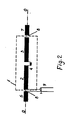
- the antenna according to FIG. 2 contains a pair 1 of half-wave dipoles 2, 3 which are connected to one another via an inductively phase-rotating circuit 4 designed as a coil with a phase shift of 60 to 120 ° el.
- a quarter-wave dipole 6 or 7 is arranged on the axis 0-0, which is connected to the pair 1 via a capacitive connection 8 with a phase shift of 60 to 120 ° el the air gap between the quarter-wave dipoles 6, 7 and their adjacent half-wave dipoles 2, 3.
- the active lead-out of the antenna is derived from the free end of the half-wave dipole 2 and the passive lead-out from the adjacent end of the quarter-wave dipole 6.
- the active lead-out can also be led out from the free end of the half-wave dipole 3 and the passive lead-out from the adjacent end of the quarter-wave dipole 7.
- antenna systems with several elements can be formed with a suitable amplitude-phase supply and coordination between the elements of the system.
- the antenna works in receive or transmit mode. It represents a colinear series of half-wave dipoles 2, 3 with alternating capacitive and inductive phase shifts, each by 60 to 120 ° el.
- the quarter-wave dipoles 6, 7 have the function of a coordinating element.
- an amplification factor of 5 is used for a phase shift with an inductive and capacitive character of 90 ° el.
- the meter wave range for frequencies from 160 MHz to 200 MHz , 7 ⁇ B for a frequency of 168 MHz with respect to the half-wave dipole 1 reached.
- a gain factor of 4.4 ⁇ B for a frequency of 525 MHz with respect to the half-wave dipole is achieved for frequencies from 450 MHz to 540 MHz.
- the antenna has an asymmetrical lead-out, which is a direct connection with an asymmetrical Lei tung, z. B. a coaxial line.
- the asymmetrical line can also be connected via a coordination link.
- the antenna can also be connected to a symmetrical line via a balancing and coordination element.
Landscapes
- Variable-Direction Aerials And Aerial Arrays (AREA)
- Radar Systems Or Details Thereof (AREA)
- Support Of Aerials (AREA)
- Details Of Aerials (AREA)
Applications Claiming Priority (2)
| Application Number | Priority Date | Filing Date | Title |
|---|---|---|---|
| BG8778857A BG45028A1 (fr) | 1987-03-12 | 1987-03-12 | |
| BG78857/87 | 1987-03-12 |
Publications (2)
| Publication Number | Publication Date |
|---|---|
| EP0285743A2 true EP0285743A2 (fr) | 1988-10-12 |
| EP0285743A3 EP0285743A3 (fr) | 1990-03-28 |
Family
ID=3918686
Family Applications (1)
| Application Number | Title | Priority Date | Filing Date |
|---|---|---|---|
| EP88100257A Withdrawn EP0285743A3 (fr) | 1987-03-12 | 1988-01-11 | Réseau linéaire de dipoles demi-onde comportant des dipoles quart d'onde aux extrémités |
Country Status (15)
| Country | Link |
|---|---|
| US (1) | US4872021A (fr) |
| EP (1) | EP0285743A3 (fr) |
| JP (1) | JPS63260203A (fr) |
| CN (1) | CN1016300B (fr) |
| AU (1) | AU598916B2 (fr) |
| BG (1) | BG45028A1 (fr) |
| BR (1) | BR8801085A (fr) |
| CS (1) | CS26288A3 (fr) |
| DK (1) | DK690887A (fr) |
| FI (1) | FI875668L (fr) |
| HU (1) | HUT46825A (fr) |
| MA (1) | MA21206A1 (fr) |
| NO (1) | NO880036L (fr) |
| PL (1) | PL271135A1 (fr) |
| YU (1) | YU788A (fr) |
Cited By (5)
| Publication number | Priority date | Publication date | Assignee | Title |
|---|---|---|---|---|
| RU2157581C1 (ru) * | 1999-01-26 | 2000-10-10 | Государственное унитарное предприятие "Воронежский научно-исследовательский институт связи" | Коллинеарная антенная система бикоаксиальных полуволновых вибраторов |
| RU2190907C2 (ru) * | 2000-09-26 | 2002-10-10 | Омский государственный технический университет | Вибраторная решетка |
| RU2385519C1 (ru) * | 2009-04-20 | 2010-03-27 | Министерство обороны Российской Федерации Государственное образовательное учреждение высшего профессионального образования ВОЕННАЯ АКАДЕМИЯ СВЯЗИ имени С.М. Буденного | Рупорная коллинеарно-микрополосковая антенна |
| ITMI20120011A1 (it) * | 2012-01-05 | 2013-07-06 | Opticos Srl | Antenna a dipolo per casco di protezione |
| RU2498466C1 (ru) * | 2012-05-11 | 2013-11-10 | Открытое акционерное общество Научно-производственный комплекс "Русская радиоэлектроника" | Коллинеарная антенна |
Families Citing this family (12)
| Publication number | Priority date | Publication date | Assignee | Title |
|---|---|---|---|---|
| US5568161A (en) * | 1994-08-05 | 1996-10-22 | Glassmaster Company | Sectionalized antenna |
| US6518934B1 (en) * | 2001-10-29 | 2003-02-11 | Northrop Grumman Corporation | Parasitically driven dipole array |
| RU2211511C1 (ru) * | 2002-01-21 | 2003-08-27 | Новочеркасский военный институт связи | Антенна для подвижной связи |
| US6771227B2 (en) * | 2002-09-19 | 2004-08-03 | Antenniques Corporation | Collinear antenna structure |
| US7098861B2 (en) * | 2004-12-28 | 2006-08-29 | Cisco Technology, Inc. | Hooked stub collinear array antenna |
| GB0515191D0 (en) * | 2005-07-25 | 2005-08-31 | Smith Stephen | Abualeiz antenna |
| JP2008306441A (ja) * | 2007-06-07 | 2008-12-18 | Dx Antenna Co Ltd | 多方向アンテナ及び組合せ多方向アンテナ |
| WO2009043055A2 (fr) * | 2007-09-28 | 2009-04-02 | Bhom Llc | Système et procédé d'extraction d'hydrocarbures par chauffage par radiofréquence in situ de formations géologiques carbonifères |
| FI125655B (fi) * | 2010-06-08 | 2015-12-31 | Cojot Oy | Yhdistelmäantenni |
| CN102110904A (zh) * | 2011-01-12 | 2011-06-29 | 中兴通讯股份有限公司 | 天线及天线排列方法 |
| EP2831950B1 (fr) * | 2012-03-29 | 2023-07-19 | Commonwealth Scientific and Industrial Research Organisation | Antenne réseau en mosaïque connectée améliorée |
| JP6411593B1 (ja) * | 2017-08-04 | 2018-10-24 | 株式会社ヨコオ | 車載用アンテナ装置 |
Family Cites Families (7)
| Publication number | Priority date | Publication date | Assignee | Title |
|---|---|---|---|---|
| BE381315A (fr) * | 1930-07-21 | |||
| US1966491A (en) * | 1930-12-01 | 1934-07-17 | Bell Telephone Labor Inc | Antenna system |
| GB436254A (en) * | 1934-07-18 | 1935-10-08 | Harold Lister Kirke | Improvements in and relating to wireless aerial systems |
| US2112287A (en) * | 1936-02-03 | 1938-03-29 | Rca Corp | Antenna |
| US2667577A (en) * | 1951-07-14 | 1954-01-26 | Motorola Inc | Antenna |
| US3016536A (en) * | 1958-05-14 | 1962-01-09 | Eugene G Fubini | Capacitively coupled collinear stripline antenna array |
| US3427624A (en) * | 1966-07-13 | 1969-02-11 | Northrop Corp | Low profile antenna having horizontal tunable top loading member |
-
1987
- 1987-03-12 BG BG8778857A patent/BG45028A1/xx unknown
- 1987-12-22 FI FI875668A patent/FI875668L/fi not_active Application Discontinuation
- 1987-12-28 JP JP62336726A patent/JPS63260203A/ja active Pending
- 1987-12-29 DK DK690887A patent/DK690887A/da not_active Application Discontinuation
-
1988
- 1988-01-05 YU YU00007/88A patent/YU788A/xx unknown
- 1988-01-06 NO NO880036A patent/NO880036L/no unknown
- 1988-01-11 EP EP88100257A patent/EP0285743A3/fr not_active Withdrawn
- 1988-01-14 CS CS88262A patent/CS26288A3/cs unknown
- 1988-01-19 HU HU88193A patent/HUT46825A/hu unknown
- 1988-02-11 CN CN88100814.1A patent/CN1016300B/zh not_active Expired
- 1988-03-08 AU AU12804/88A patent/AU598916B2/en not_active Ceased
- 1988-03-08 MA MA21447A patent/MA21206A1/fr unknown
- 1988-03-11 BR BR8801085A patent/BR8801085A/pt unknown
- 1988-03-11 PL PL27113588A patent/PL271135A1/xx unknown
- 1988-03-14 US US07/167,668 patent/US4872021A/en not_active Expired - Fee Related
Cited By (7)
| Publication number | Priority date | Publication date | Assignee | Title |
|---|---|---|---|---|
| RU2157581C1 (ru) * | 1999-01-26 | 2000-10-10 | Государственное унитарное предприятие "Воронежский научно-исследовательский институт связи" | Коллинеарная антенная система бикоаксиальных полуволновых вибраторов |
| RU2190907C2 (ru) * | 2000-09-26 | 2002-10-10 | Омский государственный технический университет | Вибраторная решетка |
| RU2385519C1 (ru) * | 2009-04-20 | 2010-03-27 | Министерство обороны Российской Федерации Государственное образовательное учреждение высшего профессионального образования ВОЕННАЯ АКАДЕМИЯ СВЯЗИ имени С.М. Буденного | Рупорная коллинеарно-микрополосковая антенна |
| ITMI20120011A1 (it) * | 2012-01-05 | 2013-07-06 | Opticos Srl | Antenna a dipolo per casco di protezione |
| EP2613406A1 (fr) * | 2012-01-05 | 2013-07-10 | Nolangroup S.p.A. | Antenne dipolaire pour casques |
| US9070978B2 (en) | 2012-01-05 | 2015-06-30 | Nolangroup S.P.A. | Dipole antenna for safety helmets |
| RU2498466C1 (ru) * | 2012-05-11 | 2013-11-10 | Открытое акционерное общество Научно-производственный комплекс "Русская радиоэлектроника" | Коллинеарная антенна |
Also Published As
| Publication number | Publication date |
|---|---|
| FI875668A7 (fi) | 1988-09-13 |
| DK690887D0 (da) | 1987-12-29 |
| AU598916B2 (en) | 1990-07-05 |
| CS26288A3 (en) | 1992-01-15 |
| AU1280488A (en) | 1988-09-15 |
| HUT46825A (en) | 1988-11-28 |
| DK690887A (da) | 1988-09-13 |
| BG45028A1 (fr) | 1989-03-15 |
| FI875668A0 (fi) | 1987-12-22 |
| CN88100814A (zh) | 1988-09-21 |
| MA21206A1 (fr) | 1988-10-01 |
| NO880036L (no) | 1988-09-13 |
| FI875668L (fi) | 1988-09-13 |
| CN1016300B (zh) | 1992-04-15 |
| PL271135A1 (en) | 1988-12-08 |
| EP0285743A3 (fr) | 1990-03-28 |
| YU788A (en) | 1990-12-31 |
| US4872021A (en) | 1989-10-03 |
| NO880036D0 (no) | 1988-01-06 |
| BR8801085A (pt) | 1988-10-18 |
| JPS63260203A (ja) | 1988-10-27 |
Similar Documents
| Publication | Publication Date | Title |
|---|---|---|
| DE2631026C2 (fr) | ||
| DE69411334T2 (de) | Streifenleitungsresonator | |
| DE69723366T2 (de) | Oberflächenmontierte Antenne und Kommunikationsgerät mit einer derartigen Antenne | |
| DE69605501T2 (de) | Chip Antenne | |
| DE69523999T2 (de) | Auf Oberflächen montierbare Antennen und Verfahren zu deren Frequenzabstimmung | |
| DE2632772C2 (de) | Mikrowellen-Gruppen-Antenne in Streifenleitungstechnik | |
| DE3243529A1 (de) | Sende/empfangsantenne mit mehreren einzelantennen und einer reziproken speiseeinrichtung | |
| DE202016008306U1 (de) | Z-förmige Doppelring-NFC-Antenne gewickelter Art und Antennensystem | |
| DE102013005984A1 (de) | Abgeschirmtes System | |
| EP1370886A2 (fr) | Dispositif pour recevoir et/ou emettre des faisceaux radar | |
| EP0114958B1 (fr) | Dispositif de couplage à micro-ondes en forme d'anneau hybride | |
| DE102016007052A1 (de) | Leiterplattenanordnung zur Signalversorgung eines Strahlers | |
| DE3427629C2 (fr) | ||
| DE102023200363A1 (de) | Leistungsteilungsvorrichtung, Wellenleiterantenne und Verfahren zum Herstellen einer Leistungsteilungvorrichtung | |
| WO2004082072A1 (fr) | Antenne multibande a capacite terminale | |
| DE19934671C1 (de) | Planare Antenne | |
| DE19531951C1 (de) | Hochfrequenzschaltverteiler | |
| DE2502376C2 (fr) | ||
| EP0518310B1 (fr) | Circuit de combinaison ou de distribution de signaux de puissance à hautes fréquences | |
| DD287634A7 (de) | Antenne | |
| DE19616252C2 (de) | Induktiv eingespeiste magnetisch wirksame Breitbandantenne | |
| DE3238806C2 (de) | Symmetriereinrichtung | |
| DE3741789C1 (en) | 180@ microwave hybrid | |
| DE1766070C2 (de) | Anordnung für die Zusammenschaltung der Ausgänge mehrerer Hochfrequenzverstärker | |
| DE424669C (de) | Antenne fuer gerichtete elektrische Wellen |
Legal Events
| Date | Code | Title | Description |
|---|---|---|---|
| PUAI | Public reference made under article 153(3) epc to a published international application that has entered the european phase |
Free format text: ORIGINAL CODE: 0009012 |
|
| AK | Designated contracting states |
Kind code of ref document: A2 Designated state(s): AT BE CH DE ES FR GB GR IT LI NL SE |
|
| PUAL | Search report despatched |
Free format text: ORIGINAL CODE: 0009013 |
|
| AK | Designated contracting states |
Kind code of ref document: A3 Designated state(s): AT BE CH DE ES FR GB GR IT LI NL SE |
|
| 17P | Request for examination filed |
Effective date: 19900509 |
|
| STAA | Information on the status of an ep patent application or granted ep patent |
Free format text: STATUS: THE APPLICATION HAS BEEN WITHDRAWN |
|
| 18W | Application withdrawn |
Withdrawal date: 19920311 |