EP0285821A2 - Procédé et dispositif de compactage de matériaux de moulage pour moules de fonderie - Google Patents
Procédé et dispositif de compactage de matériaux de moulage pour moules de fonderie Download PDFInfo
- Publication number
- EP0285821A2 EP0285821A2 EP88103415A EP88103415A EP0285821A2 EP 0285821 A2 EP0285821 A2 EP 0285821A2 EP 88103415 A EP88103415 A EP 88103415A EP 88103415 A EP88103415 A EP 88103415A EP 0285821 A2 EP0285821 A2 EP 0285821A2
- Authority
- EP
- European Patent Office
- Prior art keywords
- model
- molding
- plate
- vibrations
- oscillating
- Prior art date
- Legal status (The legal status is an assumption and is not a legal conclusion. Google has not performed a legal analysis and makes no representation as to the accuracy of the status listed.)
- Withdrawn
Links
- 238000000465 moulding Methods 0.000 title claims abstract description 44
- 238000000034 method Methods 0.000 title claims abstract description 23
- 238000007906 compression Methods 0.000 claims description 19
- 230000006835 compression Effects 0.000 claims description 15
- 239000012778 molding material Substances 0.000 claims description 14
- 230000010355 oscillation Effects 0.000 claims description 7
- 238000005056 compaction Methods 0.000 claims description 3
- 238000005429 filling process Methods 0.000 claims description 3
- 230000001133 acceleration Effects 0.000 description 2
- 230000005284 excitation Effects 0.000 description 2
- 230000003534 oscillatory effect Effects 0.000 description 2
- 238000010276 construction Methods 0.000 description 1
- 238000013016 damping Methods 0.000 description 1
- 230000003247 decreasing effect Effects 0.000 description 1
- 238000000280 densification Methods 0.000 description 1
- 230000001419 dependent effect Effects 0.000 description 1
- 238000006073 displacement reaction Methods 0.000 description 1
- 230000000694 effects Effects 0.000 description 1
- 230000002349 favourable effect Effects 0.000 description 1
- 230000005484 gravity Effects 0.000 description 1
- 230000001771 impaired effect Effects 0.000 description 1
- 238000011835 investigation Methods 0.000 description 1
- 238000011089 mechanical engineering Methods 0.000 description 1
- 230000010534 mechanism of action Effects 0.000 description 1
- 230000000704 physical effect Effects 0.000 description 1
- 239000004576 sand Substances 0.000 description 1
- 230000035939 shock Effects 0.000 description 1
Images

Classifications
-
- B—PERFORMING OPERATIONS; TRANSPORTING
- B22—CASTING; POWDER METALLURGY
- B22C—FOUNDRY MOULDING
- B22C15/00—Moulding machines characterised by the compacting mechanism; Accessories therefor
- B22C15/28—Compacting by different means acting simultaneously or successively, e.g. preliminary blowing and finally pressing
- B22C15/30—Compacting by different means acting simultaneously or successively, e.g. preliminary blowing and finally pressing by both pressing and jarring devices
Definitions
- the invention is based on a method for compressing the molding material of foundry molds in a molding space, which is delimited at the bottom by a model plate with at least one model, and laterally by a molding box with a filling frame, and in which the compression is carried out in several stages by vibrations of the model on the one hand and by pressing. or gas pressure compression takes place on the other hand.
- the requirement to treat the molding material in several stages, namely by pre-compression and post-compression, is based on the physical properties of the molding material.
- the plastic properties and good plasticity required for the sharp-edged image of the model have a negative effect on its flowability, especially with green sand which is essential for the filling process.
- Strongly profiled models, ie model surfaces with deep recesses, so-called bales with deep and narrow contours, are difficult to fill due to these molding material properties.
- the pre-compaction takes place in that the molding machine table with the overlying molding box and filling frame including the entire model device is excited vertically by a pneumatically driven vibrating anvil in such a way that the molding material filled in the molding space is brought to the tiles and pre-compressed by repeated impact impulses.
- this method has the decisive disadvantage that the mechanical shock excitation with impact impacts is extremely noisy (110-120 dBA), which no longer meets today's requirements for noise protection.
- the entire molding device is subject to high wear.
- the present invention is based on the object of specifying a compression method which is distinguished by a high molding material density even with critical model contours, but at the same time also by a drastically reduced noise development.
- the method according to the invention should work with little wear and be cost-effective to implement.
- the model carries out vibratory movements relative to the molding box.
- the invention is therefore based on a departure from the principle which is common in the vibrating and vibration molding machines, in that the model with its molding box and filling frame and the molding table are no longer shaken, but only by the model, if necessary, with its model plate relative to the in Keeping other parts at rest.
- This relative movement of the model leads to a dimensional enlargement of the impression made in the molding material. Investigations by the applicant have, however, surprisingly shown that these dimensional deviations again in the subsequent densification can be eliminated without the pre-compression of the molding material being impaired.
- Another important advantage of the method according to the invention is that the relative movements between the model and the box wall, which take place entirely or preferably in the vertical direction, transmit shear forces to the molding material, which ensure better filling and compression of the mold, especially in the critical edge area.
- the vibrating and vibrating devices which have been customary to date, with a uniform excitation of the entire molding device, however, there are no such relative movements between the model contour and the box walls.
- the oscillatory movements are carried out exclusively by the model and thus also relative to the model plate. In general, however, it is preferred for practical reasons not to disconnect the model from the model plate and instead to initiate the oscillatory movements via the model plate.
- the vibrations should at least preferably take place in the vertical direction. Certain vibrations in the horizontal direction are, however, quite permissible.
- the frequency of the vibrations is preferably between 10 Hz and 200 Hz, it being pointed out that this does not have to be harmonic vibrations and the frequency indication relates to the vibrations with the greatest amplitude, which may be overlaid by smaller vibrations.
- vibration widths of the order of magnitude of a few millimeters can be realized without problems. Accordingly, high pre-compression is obtained in the area of the model contour.
- the time for carrying out the vibration compaction is at the discretion of the person skilled in the art.
- the vibrations can take place during the filling of the molding material, instead or additionally only at the end of the filling process and / or during the post-compression phase by pressing or gas pressure.
- Vibration compression can also take place in a single step or distributed over several time intervals.
- the vibrations can be generated by pneumatic, hydraulic, mechanical or electrical forces, preferably by the overpressure of the operating air pressure network.
- a practically conventional molding machine can be used as the device for carrying out the method according to the invention, in which it is only necessary to ensure that the model, if appropriate, can carry out vibrations with its model plate relative to the molding box and filling frame.
- a vibrating device which vibrates the latter between the molding table of the molding machine and the model.
- This vibrating device can be built into the molding table, into the model plate or into any part in between, in special cases also into the model itself. It is particularly favorable if the vibrating device is installed in the model carrier, which is present anyway and is arranged between the mold table and the model plate. This enables a very compact design.
- the vibrating device itself, construction principles known per se can be used. It consists of at least two components which are guided such that they can move relative to one another, in particular vertically.
- One or an additional movable component is used to bring about the desired back and forth movement configured as a control element for generating an intermittent drive, wherein the model can return to its rest position by prestressed springs.
- the one component can be a stationary base plate connected to the model carrier, while the movable component is designed as an oscillating plate braced with the model plate, which is driven by compressed air that can be fed into the gap between the two plates, and the compressed air supply is controlled by means of a in the base plate guided control piston happens.
- a molding table 1 is guided in a manner known per se in a cylinder 2 so that it can be raised and lowered.
- the molding table 1 carries, via a base 3 and an intermediate frame 4, a molding box 5 with a filling frame 6. Above the filling frame 6 there is a press ram 7 with which the filled molding material 8 is subsequently compressed in a manner known per se.
- the model plate 8 with its model 9 is vertically displaceable relative to the molding box 5 and filling frame 6.
- the model plate 8 is dimensioned so that its outer contour is smaller than that of the molding box 5.
- This vibrating device consists of a lower base plate 11, which is fixedly connected to the center of the base 3, and of an upper, vertically movable vibrating plate 12 on which the model plate 8 is secured against Transverse displacement is firmly connected.
- the centering of the model or the model plate relative to the molding box 5 is carried out using means known per se.
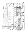
- the structure of the oscillating device 10 is clear from FIG. 2.
- the oscillating plate 12 is vertically displaceably supported on the base plate 11 by a plurality of guide bolts 13 distributed over the circumference.
- the oscillating plate 12 is prestressed in the direction of its rest position, that is to say in the direction of the base plate 11, by a plurality of prestressed spring elements, for example plate springs 14, arranged on the guide bolts 13.
- a control piston 15 is vertically displaceably mounted such that its upper piston surface can abut against the underside of the oscillating plate 12. It is designed as a stepped piston with a radially larger, upper piston part.
- the so born Dete lower ring surface 15 a is acted upon by a ring line 16 and a compressed air connection 17 with excess pressure.
- both the oscillating plate 12 and the control piston 15 are in their lower limit position.
- the control piston 15 lifts up and, with its outer surface at an appropriate stroke position, releases an annular gap 18, as a result of which the compressed air flows into the gap between the base plate and the oscillating plate.
- the pressure builds up in the said gap and thus also over the radially larger upper end face of the control piston 15.
- the oscillating plate 12, together with the clamped model lifts off from the base plate as soon as the gas pressure force in the plate gap exceeds the sum of the prestressing forces of the springs 14 and that of the mass forces.
- the plate gap opens radially on the outside, so that the compressed air flows out into the cavity of the base 3 via the gap open at the edge.
- the spring forces which increase in proportion to the stroke, and the decreasing excess pressure in the gap limit the upward stroke of the oscillating plate and, after the dynamic balance of forces has been reached, finally bring it back to the starting position.
- the movement sequence described can be significantly influenced by changing the control piston dimensions. It is both possible that the control piston and the vibrating plate perform soft vibrations without their masses colliding mechanically. Mixed operation is also possible, for example soft oscillation of the oscillating plate combined with a hard impact of the control piston on the oscillating plate or soft reversal of movement in the top dead center of the control piston with a hard impact of the oscillating plate on the fixed base plate.
- the oscillating device described also manages with very short start-up and follow-up phases, which are essentially only dependent on the switching time of the supply air valve.
- the system according to the invention can therefore be operated with short cycle times.
- the oscillating device is arranged between the molding table and the model plate. It is but of course within the scope of the invention to vary its position as well as its mechanism of action as desired. The only important thing is that the vibrations of the model take place relative to the molding box.
- the vibrating device can also be arranged on the outside of the molding machine or separately from it and can be coupled to the vibrating plate by connecting elements, plungers or the like.
Landscapes
- Engineering & Computer Science (AREA)
- Mechanical Engineering (AREA)
- Casting Devices For Molds (AREA)
Applications Claiming Priority (2)
| Application Number | Priority Date | Filing Date | Title |
|---|---|---|---|
| DE3711886 | 1987-04-08 | ||
| DE3711886 | 1987-04-08 |
Publications (2)
| Publication Number | Publication Date |
|---|---|
| EP0285821A2 true EP0285821A2 (fr) | 1988-10-12 |
| EP0285821A3 EP0285821A3 (fr) | 1988-11-30 |
Family
ID=6325157
Family Applications (1)
| Application Number | Title | Priority Date | Filing Date |
|---|---|---|---|
| EP88103415A Withdrawn EP0285821A3 (fr) | 1987-04-08 | 1988-03-05 | Procédé et dispositif de compactage de matériaux de moulage pour moules de fonderie |
Country Status (2)
| Country | Link |
|---|---|
| EP (1) | EP0285821A3 (fr) |
| DD (1) | DD281358A5 (fr) |
Cited By (3)
| Publication number | Priority date | Publication date | Assignee | Title |
|---|---|---|---|---|
| EP0380758A3 (fr) * | 1989-01-30 | 1991-10-16 | Rütgerswerke Aktiengesellschaft | Dispositif et procédé pour le remplissage dosé de moules stationnaires |
| EP1222979A4 (fr) * | 2000-04-13 | 2004-11-24 | Sintokogio Ltd | Procede et dispositif de compression pour sable de fonderie |
| EP1208928A4 (en) * | 2000-04-21 | 2005-08-17 | Sintokogio Ltd | Die molding machine and pattern carrier |
Family Cites Families (6)
| Publication number | Priority date | Publication date | Assignee | Title |
|---|---|---|---|---|
| US1605096A (en) * | 1925-01-19 | 1926-11-02 | Donald J Campbell | Pneumatically-operated molding machine |
| DE610379C (de) * | 1933-10-06 | 1935-03-18 | Zimmermann Gustav | Ruettelformmaschine |
| US2155099A (en) * | 1938-01-19 | 1939-04-18 | Earl F Oyster | Method of manufacturing sand molds for metal castings |
| DE851661C (de) * | 1948-10-02 | 1952-10-06 | Eisenwerke Ag Deutsche | Vorrichtung zum Herstellen von Giessformen auf Press- und Ruettelpress-Formmaschinen |
| DE973607C (de) * | 1949-12-06 | 1960-04-14 | Rheinstahl Eisenwerk Hilden Ag | Modelleinrichtung zum Herstellen von Giessformen auf Press- und Ruettelpress-Formmaschinen |
| DE2843598A1 (de) * | 1978-10-06 | 1980-04-17 | Arenco Bmd Maschfab | Verfahren und vorrichtung zum verdichten von giessereiformsand |
-
1988
- 1988-03-05 EP EP88103415A patent/EP0285821A3/fr not_active Withdrawn
- 1988-04-06 DD DD31446588A patent/DD281358A5/de not_active IP Right Cessation
Cited By (5)
| Publication number | Priority date | Publication date | Assignee | Title |
|---|---|---|---|---|
| EP0380758A3 (fr) * | 1989-01-30 | 1991-10-16 | Rütgerswerke Aktiengesellschaft | Dispositif et procédé pour le remplissage dosé de moules stationnaires |
| EP1222979A4 (fr) * | 2000-04-13 | 2004-11-24 | Sintokogio Ltd | Procede et dispositif de compression pour sable de fonderie |
| EP1208928A4 (en) * | 2000-04-21 | 2005-08-17 | Sintokogio Ltd | Die molding machine and pattern carrier |
| US7237593B2 (en) | 2000-04-21 | 2007-07-03 | Sintokogio, Ltd. | Molding machine and a pattern carrier used therefor |
| KR100838875B1 (ko) * | 2000-04-21 | 2008-06-16 | 신토고교 가부시키가이샤 | 주형 조형기 및 패턴 캐리어 |
Also Published As
| Publication number | Publication date |
|---|---|
| DD281358A5 (de) | 1990-08-08 |
| EP0285821A3 (fr) | 1988-11-30 |
Similar Documents
| Publication | Publication Date | Title |
|---|---|---|
| EP0326870B1 (fr) | Procédé et dispositif de compactage de sable de fonderie | |
| EP0706864B1 (fr) | Procédé pour la fabrication de blocs de construction évidés | |
| DE2843598A1 (de) | Verfahren und vorrichtung zum verdichten von giessereiformsand | |
| EP0285821A2 (fr) | Procédé et dispositif de compactage de matériaux de moulage pour moules de fonderie | |
| DE648303C (de) | Ruettelformmaschine | |
| DE3301562C1 (de) | Vorrichtung zum Herstellen von Betonsteinen | |
| DE1963640C3 (de) | Rüttelanlage zur Herstellung von Formkörpern durch Verdichtung | |
| DE102005002497B3 (de) | Verfahren und Vorrichtung zum Herstellen von Hohlbausteinen | |
| DE102004009382B3 (de) | Verfahren und Vorrichtung zum Herstellen von Betonsteinen | |
| DE2552852C3 (de) | Verfahren zum Verdichten von Formkörpern aus Beton o.dgl. plastischen Massen | |
| DE2443837C3 (de) | Verfahren zur Herstellung von Preßformkörpern, insbesondere Kalksandsteinen, sowie Preßvorrichtung zur Durchführung des Verfahrens | |
| DE2418036C3 (de) | Vorrichtung zum Verdichten oder Verformen | |
| DE2453634A1 (de) | Verfahren und vorrichtung zum verdichten von formkoerpern aus beton o.dgl. plastischen massen | |
| DE10061449A1 (de) | Verdichtungseinrichtung zur Verdichtung von aus körniger Masse bestehenden Produktkörpern | |
| CH662072A5 (de) | Maschine zum herstellen von giessformen. | |
| DE2918392C2 (de) | Rüttel-Preßformmaschine zur Herstellung von Sandformen für Gießereizwecke | |
| DE841718C (de) | Verfahren und Vorrichtung zur Herstellung verdichteter Formlinge aus keramischen Massen od. dgl. | |
| DE3329585C2 (fr) | ||
| DE2358201C3 (de) | Rüttelpreßformmaschine | |
| DE2702838C2 (de) | Formwerkzeug zur Herstellung von gelochten Kunststeinrohlingen in einer Steinpresse | |
| AT223103B (de) | Verfahren und Vorrichtung zum Pressen von körnigen, zähen plastischen Massen | |
| DE693402C (de) | tels einer Fall- oder Schlagpresse | |
| DE8003948U1 (de) | Vorrichtung zum formen von gegenstaenden aus plastischen werkstoffen | |
| DE3414715A1 (de) | Anlage zum formen von werkstuecken aus halbtrockenmassen | |
| DE1259513B (de) | Ambossruettler |
Legal Events
| Date | Code | Title | Description |
|---|---|---|---|
| PUAI | Public reference made under article 153(3) epc to a published international application that has entered the european phase |
Free format text: ORIGINAL CODE: 0009012 |
|
| PUAL | Search report despatched |
Free format text: ORIGINAL CODE: 0009013 |
|
| AK | Designated contracting states |
Kind code of ref document: A2 Designated state(s): CH DE ES FR GB IT LI SE |
|
| AK | Designated contracting states |
Kind code of ref document: A3 Designated state(s): CH DE ES FR GB IT LI SE |
|
| STAA | Information on the status of an ep patent application or granted ep patent |
Free format text: STATUS: THE APPLICATION IS DEEMED TO BE WITHDRAWN |
|
| 18D | Application deemed to be withdrawn |
Effective date: 19890531 |