EP0285827B1 - Drehmomentmesser mit Vernier-Effekt - Google Patents
Drehmomentmesser mit Vernier-Effekt Download PDFInfo
- Publication number
- EP0285827B1 EP0285827B1 EP88103492A EP88103492A EP0285827B1 EP 0285827 B1 EP0285827 B1 EP 0285827B1 EP 88103492 A EP88103492 A EP 88103492A EP 88103492 A EP88103492 A EP 88103492A EP 0285827 B1 EP0285827 B1 EP 0285827B1
- Authority
- EP
- European Patent Office
- Prior art keywords
- shaft
- section
- phase
- inductor
- vernier
- Prior art date
- Legal status (The legal status is an assumption and is not a legal conclusion. Google has not performed a legal analysis and makes no representation as to the accuracy of the status listed.)
- Expired - Lifetime
Links
- 230000000694 effects Effects 0.000 title description 3
- 230000006698 induction Effects 0.000 claims abstract description 17
- 230000010363 phase shift Effects 0.000 claims abstract description 11
- 230000000712 assembly Effects 0.000 claims 1
- 238000000429 assembly Methods 0.000 claims 1
- 238000005259 measurement Methods 0.000 abstract description 10
- 238000004804 winding Methods 0.000 description 10
- 238000010586 diagram Methods 0.000 description 7
- 230000035945 sensitivity Effects 0.000 description 4
- 230000001965 increasing effect Effects 0.000 description 3
- 238000012550 audit Methods 0.000 description 2
- 239000004020 conductor Substances 0.000 description 2
- 238000011161 development Methods 0.000 description 2
- 238000009499 grossing Methods 0.000 description 2
- 210000000056 organ Anatomy 0.000 description 2
- 239000006096 absorbing agent Substances 0.000 description 1
- 230000003321 amplification Effects 0.000 description 1
- 230000005611 electricity Effects 0.000 description 1
- 235000021183 entrée Nutrition 0.000 description 1
- 230000001939 inductive effect Effects 0.000 description 1
- 238000003780 insertion Methods 0.000 description 1
- 230000037431 insertion Effects 0.000 description 1
- 230000003993 interaction Effects 0.000 description 1
- 238000000034 method Methods 0.000 description 1
- 238000003199 nucleic acid amplification method Methods 0.000 description 1
- 238000012545 processing Methods 0.000 description 1
- 230000035939 shock Effects 0.000 description 1
- 230000001360 synchronised effect Effects 0.000 description 1
Images



Classifications
-
- G—PHYSICS
- G01—MEASURING; TESTING
- G01L—MEASURING FORCE, STRESS, TORQUE, WORK, MECHANICAL POWER, MECHANICAL EFFICIENCY, OR FLUID PRESSURE
- G01L3/00—Measuring torque, work, mechanical power, or mechanical efficiency, in general
- G01L3/02—Rotary-transmission dynamometers
- G01L3/04—Rotary-transmission dynamometers wherein the torque-transmitting element comprises a torsionally-flexible shaft
- G01L3/10—Rotary-transmission dynamometers wherein the torque-transmitting element comprises a torsionally-flexible shaft involving electric or magnetic means for indicating
- G01L3/109—Rotary-transmission dynamometers wherein the torque-transmitting element comprises a torsionally-flexible shaft involving electric or magnetic means for indicating involving measuring phase difference of two signals or pulse trains
-
- G—PHYSICS
- G01—MEASURING; TESTING
- G01L—MEASURING FORCE, STRESS, TORQUE, WORK, MECHANICAL POWER, MECHANICAL EFFICIENCY, OR FLUID PRESSURE
- G01L3/00—Measuring torque, work, mechanical power, or mechanical efficiency, in general
- G01L3/02—Rotary-transmission dynamometers
- G01L3/04—Rotary-transmission dynamometers wherein the torque-transmitting element comprises a torsionally-flexible shaft
- G01L3/10—Rotary-transmission dynamometers wherein the torque-transmitting element comprises a torsionally-flexible shaft involving electric or magnetic means for indicating
- G01L3/101—Rotary-transmission dynamometers wherein the torque-transmitting element comprises a torsionally-flexible shaft involving electric or magnetic means for indicating involving magnetic or electromagnetic means
-
- G—PHYSICS
- G01—MEASURING; TESTING
- G01L—MEASURING FORCE, STRESS, TORQUE, WORK, MECHANICAL POWER, MECHANICAL EFFICIENCY, OR FLUID PRESSURE
- G01L3/00—Measuring torque, work, mechanical power, or mechanical efficiency, in general
- G01L3/02—Rotary-transmission dynamometers
- G01L3/04—Rotary-transmission dynamometers wherein the torque-transmitting element comprises a torsionally-flexible shaft
- G01L3/10—Rotary-transmission dynamometers wherein the torque-transmitting element comprises a torsionally-flexible shaft involving electric or magnetic means for indicating
- G01L3/101—Rotary-transmission dynamometers wherein the torque-transmitting element comprises a torsionally-flexible shaft involving electric or magnetic means for indicating involving magnetic or electromagnetic means
- G01L3/104—Rotary-transmission dynamometers wherein the torque-transmitting element comprises a torsionally-flexible shaft involving electric or magnetic means for indicating involving magnetic or electromagnetic means involving permanent magnets
-
- G—PHYSICS
- G01—MEASURING; TESTING
- G01L—MEASURING FORCE, STRESS, TORQUE, WORK, MECHANICAL POWER, MECHANICAL EFFICIENCY, OR FLUID PRESSURE
- G01L3/00—Measuring torque, work, mechanical power, or mechanical efficiency, in general
- G01L3/02—Rotary-transmission dynamometers
- G01L3/04—Rotary-transmission dynamometers wherein the torque-transmitting element comprises a torsionally-flexible shaft
- G01L3/10—Rotary-transmission dynamometers wherein the torque-transmitting element comprises a torsionally-flexible shaft involving electric or magnetic means for indicating
- G01L3/101—Rotary-transmission dynamometers wherein the torque-transmitting element comprises a torsionally-flexible shaft involving electric or magnetic means for indicating involving magnetic or electromagnetic means
- G01L3/105—Rotary-transmission dynamometers wherein the torque-transmitting element comprises a torsionally-flexible shaft involving electric or magnetic means for indicating involving magnetic or electromagnetic means involving inductive means
Definitions
- the present invention relates to a vernier effect torque meter.
- the device shown in Figure 1 is also known.
- sections A and B are set the rotors 2 and 3 of two identical alternators; the rotors are respectively associated with two armatures 4 and 5 fixed to a common carcass 6 connected to the shaft 1 by bearings 7 and 8.
- Armatures 4 and 5 are electrically connected by connections 9 and 10 to a phase comparator 11.
- the measured phase shift is proportional to the torsion existing between sections A and B.
- Flanges 12 and 13 allow the device to be inserted into a line of shafts comprising the shafts 14 and 15 provided with flanges 16, 17.
- the torque exerted by a driving shaft 14 for example on the driven shaft is proportional to the torsion between the points A and B.
- the torque is therefore proportional to the measurement of the phase shift.
- N is the frequency of rotation of the tree and n the number of. pairs of alternator poles
- the frequency of the induced currents is nN; let ⁇ be the angle of twist between A and B; the phase shift corresponds to n ⁇ measured at the frequency nN.
- the precision limit of the phase meter is the most small time interval dt0 separating the waves emitted by the armature 4 and 5
- the smallest angle of torsion detected is ⁇ 0 linked to dt0 by the relation It can be seen that the measurement is all the more difficult the higher the speed; however, the latter is imposed by the system to be measured and cannot be chosen.
- An object of the present invention is to provide a torque meter giving the sensitivity, to a tree undergoing a given torsion, is multiplied by a factor equal to several tens.
- said first heteropolar vernier inductor comprises a crown of 2 alternating poles and a magnetic toothing comprising p + 1 teeth.
- said second means is a 2-pole alternator.
- said second means is a heteropolar vernier inductor comprising a crown of 2 poles in phase with the previous magnetic toothing comprising p ⁇ 1 teeth.
- the first means comprises a 2-pole alternator having an inductor linked to the shaft in the vicinity of said second section and an armature supplying a first 2-pole stator rotating practically at the speed of the shaft carrying the stator information with 2 poles of phase and constituting one of the elements of said heteropolar vernier inductor, the other element being a wheel comprising p ⁇ 1 teeth.
- said first means is a rigid elongated element fixed by a part integral with said shaft in the vicinity of said second section and extending between said first and second section so as to mechanically transmit the phase of the second section at the level of the first .
- said elongated element is a tube coaxial with the shaft.
- Figure 2 is a diagram explaining the principles of development and operation of the inventive torque meter.
- brace I The elements joined by the brace I are linked to the shaft 20 and rotate with it.
- brace II The elements joined by brace II are fixed.
- an organ 21 which provides a measurement of the phase of B.
- the measurement is transmitted by an organ 22 linked to 21 and received in a heteropolar vernier inductor 23, 24 linked to the tree which amplifies the torsion of the tree and transforms it in the form of a phase shift of a first magnetic induction 25 linked to the tree and which rotates with it.
- This induction is received by a dipole receiver 28.
- a member 26 linked to the shaft provides a phase reference in the form of a fixed induction 27 relative to the shaft which rotates with the shaft and which is received by a fixed dipole receiver 29.
- a phase comparator 30 connected to the outputs of receivers 28 and 29 provides information proportional to the phase shift, therefore to the angle of twist.
- a heteropolar vernier inductor allows very high measurement accuracy; suppose that the vernier inductor 23 comprises a ring of 2 magnetic poles cooperating with a toothing of p + 1 teeth and that a phase shift ⁇ at B is communicated by the member 22 to one of the elements of the vernier inductor heteropolar.
- the phase reference member 26 can be a dipole alternator.
- the relation (3) means that the precision of the measurement is increased by a multiplying factor equal to p.
- the number p can easily be 50 or more, which shows that the accuracy of the device can be significantly increased compared to that of the devices of the prior art, the reading frequency not exceeding that of line rotation. tree.
- the reference member 26 is another heteropolar vernier inductor, comprising 2 p alternating poles cooperating with a wheel with p-1 teeth, to which the phase difference existing between A and B is communicated, this vernier results in two macropoles phase shifted from - p ⁇ .
- the sensitivity of the measurement is then further doubled compared to the previous case.
- the sensitivity of the measurement can then exceed by 2 orders of magnitude that of the apparatus of the prior art.
- the device comprises two heteropolar vernier inductors and the phase of section B is transmitted to them electrically.
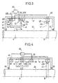
- an inductor 47 of an alternator 48 with 2p poles 47A comprising a stator armature 49 of the same polarity.
- the armature current 49 feeds two stators 42 and 52 arranged in the vicinity of section 4. These stators are each provided with a winding (resp. 42A, 52A) has 2p poles, therefore of the same polarity as the armature 49. It follows that the poles of the armature of the alternator 48 are reproduced in line with the bores of stators 42 and 52.
- the windings 42A and 52A therefore each behave as 2p poles linked to the shaft, having the phase of point B. They constitute the first part of the heteropolar vernier inductors announced.
- the stators 42 and 52 are also provided with dipole windings 42B, 52B (receivers), the respective outputs 43, 53 of which are connected to a phase comparator 60.
- the stators 42, 52 and 49 are arranged in a common magnetic carcass 61 linked to the shaft by bearings 62 and 63.
- the heteropolar vernier inductors comprise, in addition to the poles 42A, 52A, wheels 41 and 51 respectively comprising a toothed crown 44 with p-1 teeth and 45 with p + 1 teeth.
- the crowns are connected to the shaft by a common disc 64 welded to the shaft.
- FIG. 4 represents an alternative embodiment in which the 2p pole windings and the dipole windings are arranged on either side of the toothed rotors.
- the proximity of the teeth and the receptors ensures better smoothing of the output voltages sent to the comparator. Smoothing can be further improved by judicious tilting of the stator teeth.
- the two embodiments given with reference to FIGS. 3 and 4 are suitable for torque meters intended for measuring the torques of lines of shafts of large diameter rotating at relatively low speed (less than 3000 revolutions / minute).
- a disc 71 secured to a tube 72 extending coaxially with the shaft to beyond section A.
- This tube is rigid and transmits without torsion from B to A the torsion phase existing in section B.
- the tube 72 In the vicinity of point A, the tube 72 is surrounded by two stators with dipole coils 73 and 74.
- the tube carries, encased in its thickness, two rings of 2p alternating magnet magnets 75 and 76. At the level of the magnets 75 and 76 are arranged respectively two crowns of teeth 77 and 78, linked to the shaft 70 by a common disc 79.
- Crown 77 has p + 1 teeth
- crown 78 has p-1.
- the windings 73 and 74 are fixed to a carcass 80 linked to the shaft by bearings 81 and 82.
- a bearing 83 (optional) serves as a guide for the tube 72.
- the dipole windings are electrically connected to a phase comparator 85.
- the heteropolar vernier inductors are therefore here constituted one by magnets 75 and the ring gear 77, the others by the magnets 76 and the ring gear 78.
- FIG. 6 It is possible (FIG. 6) to advantageously provide the shaft with a magnetic yoke 93 covered with a layer 94 of a good conductor of electricity; the tube 72 is surrounded by a massive cylinder head 95 and provided with a crown of small alternating magnets 96.
- This assembly constitutes a torsional vibration damper with eddy currents.
- FIG. 7 the elements common to FIGS. 5 and 7 have been given the same reference number.
- the magnet rings 75A, 76A are this time linked to the shaft by a support 79A.
- the groups of p-1 and p + 1 teeth, 77A and 78A use the tube 72 as a rim and pass through it.
- the flows are, as before, communicated to the stator windings 73 and 74.
- the interaction of the phases of A and B by means of a vernier heteropolar inductor can be carried out at any level of the tree AB.
- the components of the torque meter can be mounted directly on the shaft to be monitored; alternatively, the torque meter can be mounted on a shaft section provided at its ends with flanges for its insertion in a line of shaft to be monitored.
- FIG. 8 schematically represents a torque meter intended for measuring the torsion of shafts that are not very sensitive to torsion.
- An armature 171 with N pairs of poles is linked to the shaft 101 at B. It faces a rotating inductor 172 of polarity M with magnets for example. Induced currents create M pairs of poles rotating at the speed of the inductor.
- the inductor and the two teeth which rotate at the same speed are driven if possible by a single motor 176, 176 ′ to the axis 177, which is extremely torsion-free.
- Reference 178 designates the stator carcass.
- the device described above makes it possible to measure the torsions of a shaft at very low speeds of rotation thereof, but also when stationary. It therefore allows the calibration of the shaft.
Landscapes
- Physics & Mathematics (AREA)
- General Physics & Mathematics (AREA)
- Electromagnetism (AREA)
- Electron Sources, Ion Sources (AREA)
- Synchronous Machinery (AREA)
- Investigation Of Foundation Soil And Reinforcement Of Foundation Soil By Compacting Or Drainage (AREA)
- Steroid Compounds (AREA)
- Eye Examination Apparatus (AREA)
- Food-Manufacturing Devices (AREA)
- Knives (AREA)
- Surgical Instruments (AREA)
- Measurement Of Length, Angles, Or The Like Using Electric Or Magnetic Means (AREA)
- Arrangements For Transmission Of Measured Signals (AREA)
Claims (9)
- Einrichtung zur Messung der Torsion zwischen einer ersten (A) und einer zweiten Querschnittsebene (B) einer drehenden Welle, dadurch gekennzeichnet, daß sie folgende Bestandteile aufweist:- ein erstes mit der Welle in Höhe des zweiten Querschnitts (B) verbundenes Mittel (21) zur Gewinnung und zur Übermittlung einer die Phase in Höhe des zweiten Querschnitts (B) wiedergebenden Information in den Bereich des ersten Querschnitts (B),- einen heteropolaren Vernierinduktor, von dem ein Element (23) mit der Welle in Höhe des ersten Querschnitts (A) verbunden ist und der die Information über sein anderes Element (24) empfängt und in Form einer Phasenverschiebung einer ersten resultierenden magnetischen Induktion (25) verstärkt, die an die Bezugsmarke der Welle gebunden ist und mit dieser umläuft,- einen ersten ortsfesten Dipol-Aufnehmer (28), der von der genannten magnetischen Induktion induktiv beeinflußt wird,- einen zweiten ortsfesten Dipol-Aufnehmer (29), der von einer zweiten magnetischen Induktion (27), die der Bezugsmarke der Welle im Bereich des ersten Querschnitts (A) zugeordnet ist, induktiv beeinflußt wird und die durch ein zweites einen Phasenbezug bildendes Mittel (26) geliefert wird, und einen Phasenkomparator (30), der an seinen Eingängen die von den Aufnehmern (28, 29) abgegebenen Signale empfängt und ein Ausgangssignal liefert, das der Differenz zwischen den Phasen der genannten Signale und somit dem Torsionswinkel proportional ist.
- Einrichtung nach Anspruch 1, dadurch gekennzeichnet, daß der erste heteropolare Vernierinduktor einen Kranz (23) mit 2p alternierenden Polen und eine magnetischen Zahnung mit p ± 1 Zähnen aufweist.
- Einrichtung nach Anspruch 1 oder 2, dadurch gekennzeichnet, daß das zweite Mittel (26) ein zweipoliger Wechselstromgenerator ist.
- Einrichtung nach Anspruch 1 oder 2, dadurch gekennzeichnet, daß das zweite Mittel (26) ein heteropolarer Vernierinduktor mit einem mit dem vorhergehenden Kranz phasengleichen Kranz mit 2p Polen, und mit einer magnetischen Zahnung mit p + 1 Zähnen ist.
- Einrichtung nach Anspruch 3, dadurch gekennzeichnet, daß das erste Mittel einen Wechselstromgenerator (48) mit 2p Polen aufweist, der einen mit der Welle in Höhe des zweiten Querschnitts verbundenen Induktor (47) besitzt, und daß es eine Ankerwicklung (49) aufweist, die einen ersten Stator (42) mit 2p Polen speist und praktisch mit der Geschwindigkeit der die Phaseninformation tragenden Welle umläuft und das eine der Elemente des heteropolaren Vernierinduktors bildet, während das andere Element ein Rad mit p ± 1 Zähnen ist.
- Einrichtung nach Anspruch 4, dadurch gekennzeichnet, daß das erste Mittel einen Wechselstromgenerator (48) mit 2p Polen aufweist, der einen mit der Welle in Höhe des zweiten Querschnitts verbundenen Induktor (47) besitzt, und daß es eine Ankerwicklung (49) aufweist, die einen ersten Stator (52) mit 2p Polen speist und praktisch mit der Geschwindigkeit der die Phaseninformation tragenden Welle umläuft und das eine der Elemente des zweiten heteropolaren Vernierinduktors bildet, wahrend die anderen Elemente ein magnetisches Rad (44) mit p±1 Zähnen bzw. ein magnetisches Rad (45) mit p∓1 Zähnen ist.
- Einrichtung nach Anspruch 6, dadurch gekennzeichnet, daß die magnetischen Räder (44, 45) zwischen einem Stator (42, 52) und einem Aufnehmer (46, 58) angeordnet sind.
- Einrichtung nach den Ansprüchen 1 bis 4, dadurch gekennzeichnet, daß das erste Mittel ein starres, längliches Element (72) ist, das durch ein fest mit der Welle in Höhe des zweiten Querschnitts (B) verbundenes Teil (71) befestigt ist und sich zwischen dem ersten (A) und dem zweiten Querschnitt (B) erstreckt, derart, daß es ohne Verdrehung mechanisch die Phase des zweiten Querschnitts (B) in den Bereich des ersten Querschnitts (A) überträgt.
- Einrichtung zur Messung der Torsion zwischen einem ersten (A) und einem zweiten Querschnitt (B) einer Welle bei sehr niedrigen Umdrehungsgeschwindigkeiten derselben und sogar bei Stillstand, dadurch gekennzeichnet, daß sie folgende Bestandteile aufweist:- eine erste Ankerwicklung mit N Polpaaren (171), die in Höhe des zweiten Querschnitts (B) festgekeilt istd und einem umlaufenden Induktor der Polarität N mit Magneten gegenübersteht,- zwei Verniereinheiten, bestehend aus einer zweiten und einer dritten Ankerwicklung (171', 171"), die in Höhe des ersten Querschnitts (A) festgekeilt sind und von dem in der ersten Ankerwicklung (171) induzierten Strom durchflossen werden,- wobei die zweiten und dritten Ankerwicklungen (171', 171") magnetischen Zahnungen (173, 174) gegenüberstehen, die N+1 bzw. N-1 Zähne besitzen,- einen ersten (175A) und einen zweiten festen Aufnehmer (175B), welche die von den beiden Verniereinheiten (171', 171") erzeugten Induktionen aufnehmen, und- ein Mittel zum Messen der Phasenverschiebung zwischen den genannten Induktionen, die der Torsion proportional ist.
Priority Applications (1)
| Application Number | Priority Date | Filing Date | Title |
|---|---|---|---|
| AT88103492T ATE64008T1 (de) | 1987-03-17 | 1988-03-07 | Drehmomentmesser mit vernier-effekt. |
Applications Claiming Priority (2)
| Application Number | Priority Date | Filing Date | Title |
|---|---|---|---|
| FR8703638 | 1987-03-17 | ||
| FR8703638A FR2612633B1 (fr) | 1987-03-17 | 1987-03-17 | Couplemetre a effet vernier |
Publications (3)
| Publication Number | Publication Date |
|---|---|
| EP0285827A2 EP0285827A2 (de) | 1988-10-12 |
| EP0285827A3 EP0285827A3 (en) | 1988-10-19 |
| EP0285827B1 true EP0285827B1 (de) | 1991-05-29 |
Family
ID=9349066
Family Applications (1)
| Application Number | Title | Priority Date | Filing Date |
|---|---|---|---|
| EP88103492A Expired - Lifetime EP0285827B1 (de) | 1987-03-17 | 1988-03-07 | Drehmomentmesser mit Vernier-Effekt |
Country Status (5)
| Country | Link |
|---|---|
| US (1) | US4918997A (de) |
| EP (1) | EP0285827B1 (de) |
| AT (1) | ATE64008T1 (de) |
| DE (1) | DE3862984D1 (de) |
| FR (1) | FR2612633B1 (de) |
Cited By (2)
| Publication number | Priority date | Publication date | Assignee | Title |
|---|---|---|---|---|
| DE10160760A1 (de) * | 2001-12-11 | 2003-06-26 | Walterscheid Gmbh Gkn | Antriebswelle mit Mitteln zur Drehmomentmessung |
| US7104133B2 (en) | 2002-03-28 | 2006-09-12 | Kabushiki Kaisha Toshiba | Torsional vibration measuring instrument |
Families Citing this family (11)
| Publication number | Priority date | Publication date | Assignee | Title |
|---|---|---|---|---|
| FR2649558B1 (fr) * | 1989-07-07 | 1991-09-20 | Thomson Csf | Dispositif de mesure dynamique du couple d'un moteur autosynchrone et dispositif de commande asservie d'un moteur autosynchrone utilisant ce dispositif |
| US7198969B1 (en) * | 1990-09-24 | 2007-04-03 | Tessera, Inc. | Semiconductor chip assemblies, methods of making same and components for same |
| TW227601B (de) * | 1993-01-25 | 1994-08-01 | Gen Electric | |
| FR2712982B1 (fr) * | 1993-11-26 | 1996-02-09 | Labinal | Dispositif de mesure différentielle de couple. |
| DE19941464A1 (de) | 1999-09-01 | 2001-03-15 | Hella Kg Hueck & Co | Induktiver Positionssensor |
| GB0219745D0 (en) * | 2002-08-23 | 2002-10-02 | Fast Technology Ag | Torque sensor adaptor |
| US8001848B2 (en) * | 2007-12-18 | 2011-08-23 | Deere & Company | Torque measurement method and apparatus |
| DE102008006865B4 (de) * | 2008-01-31 | 2024-02-29 | HELLA GmbH & Co. KGaA | Induktiver Drehmomentsensor |
| EP2478338B1 (de) * | 2009-09-16 | 2015-10-14 | Micro-Sensys GmbH | Anordnung zur bestimmung von verdrehungen von lang gestreckten körpern |
| US8742715B2 (en) | 2011-06-09 | 2014-06-03 | Simmonds Precision Products, Inc. | System and method for providing control of an electric motor using inductive rotary sensor |
| JP6059620B2 (ja) * | 2013-09-12 | 2017-01-11 | Ntn株式会社 | トルクセンサユニット |
Family Cites Families (5)
| Publication number | Priority date | Publication date | Assignee | Title |
|---|---|---|---|---|
| US3194065A (en) * | 1961-04-04 | 1965-07-13 | Meredith W Wilson | Digital vernier torquemeter |
| SE321811B (de) * | 1966-03-16 | 1970-03-16 | Jungner Instrument Ab | |
| GB1201310A (en) * | 1966-09-27 | 1970-08-05 | Rolls Royce | Electrical pulse transmitting apparatus |
| GB1281339A (en) * | 1968-09-13 | 1972-07-12 | Hawker Siddeley Dynamics Ltd | Improvements in the measurements of twist in rotating shafts |
| JPS58167934A (ja) * | 1982-03-29 | 1983-10-04 | Omron Tateisi Electronics Co | トルク検出装置 |
-
1987
- 1987-03-17 FR FR8703638A patent/FR2612633B1/fr not_active Expired
-
1988
- 1988-03-07 AT AT88103492T patent/ATE64008T1/de not_active IP Right Cessation
- 1988-03-07 EP EP88103492A patent/EP0285827B1/de not_active Expired - Lifetime
- 1988-03-07 DE DE8888103492T patent/DE3862984D1/de not_active Expired - Fee Related
- 1988-03-17 US US07/169,535 patent/US4918997A/en not_active Expired - Fee Related
Cited By (3)
| Publication number | Priority date | Publication date | Assignee | Title |
|---|---|---|---|---|
| DE10160760A1 (de) * | 2001-12-11 | 2003-06-26 | Walterscheid Gmbh Gkn | Antriebswelle mit Mitteln zur Drehmomentmessung |
| DE10160760B4 (de) * | 2001-12-11 | 2005-06-16 | Gkn Walterscheid Gmbh | Antriebswelle mit Mitteln zur Drehmomentmessung |
| US7104133B2 (en) | 2002-03-28 | 2006-09-12 | Kabushiki Kaisha Toshiba | Torsional vibration measuring instrument |
Also Published As
| Publication number | Publication date |
|---|---|
| ATE64008T1 (de) | 1991-06-15 |
| EP0285827A2 (de) | 1988-10-12 |
| US4918997A (en) | 1990-04-24 |
| FR2612633A1 (fr) | 1988-09-23 |
| EP0285827A3 (en) | 1988-10-19 |
| FR2612633B1 (fr) | 1989-05-05 |
| DE3862984D1 (de) | 1991-07-04 |
Similar Documents
| Publication | Publication Date | Title |
|---|---|---|
| EP0522941B1 (de) | Einrichtung zur Messung der Winkellage eines Rotors in bezüglich eines Stators | |
| EP0285827A2 (de) | Drehmomentmesser mit Vernier-Effekt | |
| EP0251918B1 (de) | Winkelpositionsaufnehmer und Winkelpositionsmessgerät mit mehreren von diesen Aufnehmern | |
| EP0682238B1 (de) | Magnetisches Torsionsmessgerät zur absoluten Messung von Verdrehung und Drehmoment | |
| EP0170558A1 (de) | Anordnung zum Erzeugen und/oder Empfangen von Wechselmagnetfeldern für mit magnetischer Kernresonanz arbeitende Apparate | |
| EP0681690B1 (de) | Messvorrichtung zur differentiellen messung von momenten | |
| EP1285220B1 (de) | Sternschaltung mit sensoren | |
| EP1037015A1 (de) | Magnetische Positions- und Richtungserfassung | |
| CA1072194A (fr) | Codeur de position associe a une machine a reluctance variable | |
| EP0479674B1 (de) | Vervollkommnung der Einrichtungen zur Messung der Bremsmomente, erzeugt durch elektromagnetische Bremsvorrichtungen und Regeleinrichtungen dieser Momente | |
| EP0443937B1 (de) | Geschwindigkeitsmessaufnehmer für den Ausgang eines Getriebes | |
| EP0500431B1 (de) | Winkelgeber, insbesondere für drehende Maschinen mit sehr hoher Laufgeschwindigkeit | |
| EP0343074B1 (de) | Vorrichtung zum Messen von Winkelphasenverschiebungen und Anwendung als Torsionsmessgerät | |
| EP0401084B1 (de) | Vorrichtung mit mehreren Winkelpositionssensoren | |
| EP1166295B1 (de) | Verfahren zur positionsbestimmung eines beweglichen elements in mindestens einem hauptluftspalt eines elektromagnetischen aktuators | |
| FR2637683A1 (fr) | Dispositif pour la mesure de la position angulaire et du deplacement lineaire de deux pieces l'une par rapport a l'autre | |
| FR3105436A1 (fr) | Dispositif et procédé de mesure des pertes fer dans un échantillon magnétique doux soumis à un champ magnétique tournant | |
| EP0370839B1 (de) | Messanordnung für Winkelposition und Linearverschiebung | |
| FR3114654A1 (fr) | Dispositif de mesure de vitesse de rotation et train d’atterrissage équipé d’un tel dispositif | |
| EP0336795A1 (de) | Mechanischer Mehrfach-Trägheitssensor | |
| FR2473724A1 (fr) | Capteur de mesure de vitesse angulaire | |
| FR2547056A1 (fr) | Dispositif pour detecter les defauts dans des tubes metalliques | |
| FR2521296A1 (fr) | Circuit d'alimentation d'une sonde a courants de foucault | |
| FR2609554A1 (fr) | Dispositif de mesure de l'angle interne d'une machine electrique | |
| BE480124A (fr) | Système de transmission du mouvement à distance |
Legal Events
| Date | Code | Title | Description |
|---|---|---|---|
| PUAI | Public reference made under article 153(3) epc to a published international application that has entered the european phase |
Free format text: ORIGINAL CODE: 0009012 |
|
| PUAL | Search report despatched |
Free format text: ORIGINAL CODE: 0009013 |
|
| AK | Designated contracting states |
Kind code of ref document: A2 Designated state(s): AT CH DE FR GB IT LI SE |
|
| AK | Designated contracting states |
Kind code of ref document: A3 Designated state(s): AT CH DE FR GB IT LI SE |
|
| 17P | Request for examination filed |
Effective date: 19890417 |
|
| 17Q | First examination report despatched |
Effective date: 19900328 |
|
| RAP1 | Party data changed (applicant data changed or rights of an application transferred) |
Owner name: SOCIETE ANONYME DITE: CEGELEC |
|
| GRAA | (expected) grant |
Free format text: ORIGINAL CODE: 0009210 |
|
| AK | Designated contracting states |
Kind code of ref document: B1 Designated state(s): AT CH DE FR GB IT LI SE |
|
| REF | Corresponds to: |
Ref document number: 64008 Country of ref document: AT Date of ref document: 19910615 Kind code of ref document: T |
|
| REF | Corresponds to: |
Ref document number: 3862984 Country of ref document: DE Date of ref document: 19910704 |
|
| GBT | Gb: translation of ep patent filed (gb section 77(6)(a)/1977) | ||
| ITF | It: translation for a ep patent filed | ||
| PLBE | No opposition filed within time limit |
Free format text: ORIGINAL CODE: 0009261 |
|
| STAA | Information on the status of an ep patent application or granted ep patent |
Free format text: STATUS: NO OPPOSITION FILED WITHIN TIME LIMIT |
|
| 26N | No opposition filed | ||
| EAL | Se: european patent in force in sweden |
Ref document number: 88103492.0 |
|
| PGFP | Annual fee paid to national office [announced via postgrant information from national office to epo] |
Ref country code: GB Payment date: 19970213 Year of fee payment: 10 |
|
| PGFP | Annual fee paid to national office [announced via postgrant information from national office to epo] |
Ref country code: FR Payment date: 19970214 Year of fee payment: 10 |
|
| PGFP | Annual fee paid to national office [announced via postgrant information from national office to epo] |
Ref country code: DE Payment date: 19970220 Year of fee payment: 10 Ref country code: AT Payment date: 19970220 Year of fee payment: 10 |
|
| PGFP | Annual fee paid to national office [announced via postgrant information from national office to epo] |
Ref country code: SE Payment date: 19970221 Year of fee payment: 10 |
|
| PGFP | Annual fee paid to national office [announced via postgrant information from national office to epo] |
Ref country code: CH Payment date: 19970226 Year of fee payment: 10 |
|
| PG25 | Lapsed in a contracting state [announced via postgrant information from national office to epo] |
Ref country code: GB Free format text: LAPSE BECAUSE OF NON-PAYMENT OF DUE FEES Effective date: 19980307 Ref country code: AT Free format text: LAPSE BECAUSE OF NON-PAYMENT OF DUE FEES Effective date: 19980307 |
|
| PG25 | Lapsed in a contracting state [announced via postgrant information from national office to epo] |
Ref country code: SE Free format text: LAPSE BECAUSE OF NON-PAYMENT OF DUE FEES Effective date: 19980308 |
|
| PG25 | Lapsed in a contracting state [announced via postgrant information from national office to epo] |
Ref country code: LI Free format text: LAPSE BECAUSE OF NON-PAYMENT OF DUE FEES Effective date: 19980331 Ref country code: FR Free format text: THE PATENT HAS BEEN ANNULLED BY A DECISION OF A NATIONAL AUTHORITY Effective date: 19980331 Ref country code: CH Free format text: LAPSE BECAUSE OF NON-PAYMENT OF DUE FEES Effective date: 19980331 |
|
| GBPC | Gb: european patent ceased through non-payment of renewal fee |
Effective date: 19980307 |
|
| REG | Reference to a national code |
Ref country code: CH Ref legal event code: PL |
|
| PG25 | Lapsed in a contracting state [announced via postgrant information from national office to epo] |
Ref country code: DE Free format text: LAPSE BECAUSE OF NON-PAYMENT OF DUE FEES Effective date: 19981201 |
|
| EUG | Se: european patent has lapsed |
Ref document number: 88103492.0 |
|
| REG | Reference to a national code |
Ref country code: FR Ref legal event code: ST |
|
| PG25 | Lapsed in a contracting state [announced via postgrant information from national office to epo] |
Ref country code: IT Free format text: LAPSE BECAUSE OF NON-PAYMENT OF DUE FEES;WARNING: LAPSES OF ITALIAN PATENTS WITH EFFECTIVE DATE BEFORE 2007 MAY HAVE OCCURRED AT ANY TIME BEFORE 2007. THE CORRECT EFFECTIVE DATE MAY BE DIFFERENT FROM THE ONE RECORDED. Effective date: 20050307 |