EP0285924A2 - Chaussure de ski - Google Patents
Chaussure de ski Download PDFInfo
- Publication number
- EP0285924A2 EP0285924A2 EP88104788A EP88104788A EP0285924A2 EP 0285924 A2 EP0285924 A2 EP 0285924A2 EP 88104788 A EP88104788 A EP 88104788A EP 88104788 A EP88104788 A EP 88104788A EP 0285924 A2 EP0285924 A2 EP 0285924A2
- Authority
- EP
- European Patent Office
- Prior art keywords
- folding element
- ski boot
- shoe
- pressure plate
- boot according
- Prior art date
- Legal status (The legal status is an assumption and is not a legal conclusion. Google has not performed a legal analysis and makes no representation as to the accuracy of the status listed.)
- Granted
Links
Images



Classifications
-
- A—HUMAN NECESSITIES
- A43—FOOTWEAR
- A43B—CHARACTERISTIC FEATURES OF FOOTWEAR; PARTS OF FOOTWEAR
- A43B5/00—Footwear for sporting purposes
- A43B5/04—Ski or like boots
- A43B5/0427—Ski or like boots characterised by type or construction details
- A43B5/0435—Adjustment of the boot to the foot
- A43B5/0443—Adjustment of the boot to the foot to the instep of the foot, e.g. metatarsals; Metatarsal clamping devices
-
- A—HUMAN NECESSITIES
- A43—FOOTWEAR
- A43B—CHARACTERISTIC FEATURES OF FOOTWEAR; PARTS OF FOOTWEAR
- A43B5/00—Footwear for sporting purposes
- A43B5/04—Ski or like boots
- A43B5/0427—Ski or like boots characterised by type or construction details
- A43B5/0429—Adjustment of the boot to calf or shin, i.e. fibula, tibia
- A43B5/0433—Adjustment of the boot to calf or shin, i.e. fibula, tibia to the width of calf or shin, i.e. fibula, tibia
Definitions
- the invention relates to a ski boot according to the preamble of claim 1.
- Such a ski boot is described for example in AT-B 380 774.
- a pressure plate is arranged between the outer shoe and the inner shoe, which can be tensioned by means of a pull rope.
- One end of the pull rope is attached to a shoulder tab of the rear shaft part.
- the traction cable is guided over the pressure plate, deflected by means of a deflection roller mounted on the other side of the shoe, and again guided back via the pressure plate to an angle roller, which is mounted in the attachment tab. Due to the fact that the traction cable acts twice directly on the pressure plate transversely to the longitudinal direction of the foot, a locally excessive load is exerted on the foot of the skier.
- an instep bandage is arranged between the outer boot and the inner boot, which can be tensioned or relaxed by means of two pull ropes, which are led to the rear of the ski boot via deflections (see brochure from Kastinger 1980).
- an exact adjustment of the instep band to the foot of the respective skier is required to prevent the formation of pressure points.
- this may not be possible in the mass production of ski boots.
- the object of the invention is to eliminate the disadvantages of the known designs and to provide a ski boot in which the fixing of the foot in the ski boot is brought about without the risk of pressure points occurring.
- this object is achieved according to the invention by the measure of the characterizing part of this claim.
- the use of a folding element ensures a particularly favorable force distribution on the pressure plate and thus also in the instep area of the skier.
- a folding element is used, which rests with one side against the pressure plate and with its other side against the inner wall of the outer shoe and its position can be adjusted by means of the pull rope.
- a folding element designed in this way cannot be found in any of the provisions mentioned.
- two pairs of connecting lugs which can be actuated by the handle by means of the rod provided with the two opposite threaded sections, act on an adjusting member.
- This adjusting element can be arranged either in the heel area of the ski shoe according to FIG. 3, in the front area of the ski shoe shaft according to FIG. 4, or on the rear of the ski shoe shaft according to FIG.
- this known solution does not remedy the disadvantage which occurs in the prior art taken into account, namely the risk of local pressure points, and the measure according to the invention of providing a folding element within the meaning of claim 1 is not suggested.
- EP-A1-165 495 deviates from the solution just treated in that a push-off plate (presser 6) is provided, on which a plate and an unspecified fastening plate are arranged.
- the plate carries the two pairs of connecting straps (here designated 4 and 10), each of which acts on the plate at separate joint axes which are spaced apart from one another.
- the length dimension of the two driver pawls (pawls 3) which can be actuated by means of the rod is lengthened to an extent which corresponds to the distance between the two joint axes.
- a connecting rod with lower and upper connecting straps is articulated on the outer shoe or on the pressure plate.
- claim 2 allow direct actuation of the folding element by the cable.
- the use of a T-shaped end piece at the end of the cable pull remote from the handle is necessary for this.
- the individual links of the folding element must have bores for the cable to be passed through.
- the upper end of the folding element could also be attached to the pressure plate. For manufacturing reasons, however, it has proven to be useful if the features of claim 4 or 5 are realized to support the folding element on the pressure plate.
- the folding element can be arranged in the area of the instep (see Claim 6) or above the heel in the rear upper area (see Claim 7) or in the sole area (see Claim 8). It is ensured by the features of claim 9 that the handle does not hinder skiing, particularly in this embodiment.
- the measure of claim 10 enables on the one hand a reliable holding of the inner shoe in relation to the outer shoe in the spread position of the folding element and, on the other hand, after loosening the pull rope, an automatic return of the folding element to the extended position without additional springs being required for this.
- the subject of claim 11 ensures a good adaptation of the pressure plate to the foot of the skier.
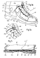
- FIG. 1 shows a diagram of the first embodiment of the ski boot with the pull rope loosened, with part of the outer shoe broken away
- FIG. 2 is a partially sectioned side view of the ski boot, likewise with the pull rope loosened
- FIG. 3 shows a partially sectioned side view with the pull rope pulled.
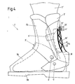
- 4 shows a partial section through a second embodiment, in which the traction cable is in the loosened position.
- Fig.1a shows a modification of the arrangement of the pull rope on the folding element, similar to Fig.1, Fig.1b shows a modification of the support of the folding element on the pressure plate.
- 5 shows a partial section through the sole of a ski boot, in which embodiment the pull rope is in the loosened position.
- 1 denotes the ski boot in its entirety. It has an inner shoe 2 split into two halves in the region of the shaft and an outer shoe 3.
- the latter consists of a base part 3a, a front shaft part 3b and a rear shaft part 3c.
- the shaft parts 3b and 3c are articulated to the base part 3a by means of axles 4 and 5, respectively, in order to make it easier to get in and on the other hand to drive in the template.
- a sole 3d is attached to the base part 3a.
- the front shaft part 3b carries a tensioning strap 6, which is fastened to the latter with a section and can be brought into engagement with a buckle 6a for holding the rear shaft part 3 by means of its free end region.
- the tensioning belt 6 has teeth 6b in a known manner for better engagement with the buckle 6a. With 7 the only indicated lower leg of the skier is designated.
- a pressure plate 8 is placed on the inner shoe 2, which is made of a material which is flexible in the transverse direction and is adapted to the shape of the inner shoe.
- the pressure plate 8 carries hooks 8a or projections at its upper end. In order to increase the flexibility of the pressure plate 8, it has notches 8b in the area of its two sides, which are preferably triangular.
- a folding element 9 is supported with its edges, the opposite edges of which bear against the inside of the outer shoe 3.
- the folding element 9 is penetrated by a pull rope 10, one end of which is attached to the end of the folding element 9.
- the opposite end of the folding element 9 is supported on the hook 8a.
- the adjoining plates of the folding element 9 enclose an angle of 70-90 ° with the tension cable 10 tensioned and an angle of 130-160 ° with the tension cable 10 loosened.
- the other end of the pull rope is attached to a winding roller 1, the axis 12 of which passes through the outer shoe 3 and a e.g. designed as a handle 13 carries.
- the knob 13 is held in place by friction.
- the distance between the pressure plate 8 and the outer shoe 3 is denoted by a 1 (see FIG. 2).
- the pull rope 10 is first loosened by means of the rotary knob 13 and the tensioner of the tensioning belt 6 is opened so that the rear shaft part 3 c can be pivoted back together with the associated half of the inner boot 2.
- the skier's foot is then inserted into the inner shoe 2 until it rests on the sole 3d.
- the rear shaft part 3c is pivoted forward and held on the front shaft part 3b by means of the tensioning belt 6 and the buckle 6a.
- the rotary knob 13 is turned.
- the individual plates of the folding element 9 press Pressure plate 8 away from the inside of the outer shoe 3, so that there is an increased distance a2 between the pressure plate 8 and the outer shoe 3 (see Fig. 3).
- the turning of the rotary knob 13 is ended.
- the foot of the skier is thus fixed in ski boot 1.
- the rotary knob 13 is first turned in the opposite direction, so that the pull rope 10 is loosened. Then the tensioning belt 6 is opened by means of the tensioner. The rear shaft part 3c can then be pivoted back and the foot can be pulled out of the inner shoe 2.
- the ski boot 1 ⁇ shown in Figure 4 differs from the ski boot described first in that the pressure plate 8 ⁇ , the folding element 9 ⁇ , the pull rope 10 ⁇ and the tensioning device in the form of a winding roller 11 ⁇ , which can be rotated with the rotary knob 13 ⁇ , not in Area of the instep, but located in the rear shaft area 3 ⁇ c in the ski boot 1 ⁇ .
- the remaining structure of the ski boot 1 ⁇ corresponds to that of the ski boot 1 described first.
- the folding element 9element has eyelets 9 ⁇ a on the side faces of its members, through which the pulling rope 10 ⁇ is guided.
- the free end 10 ⁇ b of the pull rope 10 ⁇ which is remote from the handle 13 ⁇ is attached to the base part 3 ⁇ a of the outer shoe 3 ⁇ .
- the pull rope 10 ⁇ is actuated — similarly to the exemplary embodiment according to FIG. 1 — via a winding roller 11 ⁇ by means of a handle 13 ⁇ designed as a rotary knob.
- the variant shown in Fig.1b relates to another type of support of the folding element 9 ′′′ on the pressure plate 8 ′′′.
- the member of the folding element 9 ′′′ facing the pressure plate 8 ′′′ has extensions 9 ′′′ a which engage in slots 8 ′′′ a of the pressure plate 8 ′′′.
- FIGS. 1a and 1b correspond to what has already been described. For the sake of better distinction, they were simply marked with digits " designated.
- FIG. 5 shows the use of the invention in the sole area of a ski boot 1 IV , only the sole area being shown in section in this FIG.
- the folding element 9 IV is arranged between the inner shoe 2 IV and the outer shoe 3 IV
- the pressure plate 8 IV which in the present case consists of a rigid material, on the outer shoe 3 IV , preferably in the front sole area, by means of a transverse axis 3 IV e is articulated.
- Paragraph 3 IV f of the ski boot 1 IV is suitable for accommodating the winding roller 11 IV and the axis 12 IV of the handle, not shown here, designed as a rotary knob.
- the handle can also be designed in the form of a key, in which case the axis 12 IV , as is known per se in the case of such devices, is provided with an angular cross-section to which the key provided with a congruent connection area can be adapted.
- ski boots in which entry is not from the rear, as shown, but from the front are also to be covered by the protection of the invention.
- the tongue must be covered on its inside with a further pressure plate, which ensures a smooth sliding of the folding element when tensioning and when loosening the pull rope.
- FIGS. 1a and 1b can be used in conjunction with one of the embodiments according to FIGS. 4 or 5.
- a combination of the configuration according to FIGS. 1a and 1b with that according to FIG. 1 is also conceivable.
- the articulated arrangement of the pressure plate according to FIG. 5 can also be used in connection with the configuration according to one of FIGS. 1, 1a or 4.
Landscapes
- Health & Medical Sciences (AREA)
- General Health & Medical Sciences (AREA)
- Physical Education & Sports Medicine (AREA)
- Footwear And Its Accessory, Manufacturing Method And Apparatuses (AREA)
Applications Claiming Priority (2)
| Application Number | Priority Date | Filing Date | Title |
|---|---|---|---|
| AT85887A AT389212B (de) | 1987-04-08 | 1987-04-08 | Skischuh |
| AT858/87 | 1987-04-08 |
Publications (3)
| Publication Number | Publication Date |
|---|---|
| EP0285924A2 true EP0285924A2 (fr) | 1988-10-12 |
| EP0285924A3 EP0285924A3 (en) | 1990-09-12 |
| EP0285924B1 EP0285924B1 (fr) | 1993-05-19 |
Family
ID=3501427
Family Applications (1)
| Application Number | Title | Priority Date | Filing Date |
|---|---|---|---|
| EP19880104788 Expired - Lifetime EP0285924B1 (fr) | 1987-04-08 | 1988-03-25 | Chaussure de ski |
Country Status (3)
| Country | Link |
|---|---|
| EP (1) | EP0285924B1 (fr) |
| AT (1) | AT389212B (fr) |
| DE (1) | DE3881092D1 (fr) |
Cited By (2)
| Publication number | Priority date | Publication date | Assignee | Title |
|---|---|---|---|---|
| US4945660A (en) * | 1987-11-10 | 1990-08-07 | Salomon S.A. | Ski boot |
| US5386650A (en) * | 1987-11-27 | 1995-02-07 | Kneissl Dachstein Sportartikel Aktiengellschaft | Ski boot with a damping device between the shell and shaft |
Families Citing this family (1)
| Publication number | Priority date | Publication date | Assignee | Title |
|---|---|---|---|---|
| FR3117744B1 (fr) * | 2020-12-18 | 2023-11-17 | Salomon Sas | Chaussure de ski et dispositif de serrage |
Family Cites Families (6)
| Publication number | Priority date | Publication date | Assignee | Title |
|---|---|---|---|---|
| DE2317408C2 (de) * | 1972-04-17 | 1982-12-23 | Etablissements François Salomon et Fils, 74011 Annecy, Haute-Savoie | Skischuh |
| FR2345097A1 (fr) * | 1976-03-24 | 1977-10-21 | Salomon & Fils F | Chaussure de ski comportant un systeme de tenue de pied actionne par la fermeture d'une partie de la chaussure |
| DE2738523C3 (de) * | 1977-08-26 | 1981-04-02 | Bernhard 5500 Trier Kirsch | Skistiefel |
| IT8122770U1 (it) * | 1981-01-31 | 1982-07-31 | Nordica Spa | Dispositivo di regolazione particolarmente per scarponi da sci |
| IT1174106B (it) * | 1984-05-29 | 1987-07-01 | Nordica Spa | Dispositivo di azionamento del pressore del collo del piede particolarmente in scorponi da sci |
| AT380774B (de) * | 1984-10-31 | 1986-07-10 | Lintner Dachstein Sportschuh | Skischuh |
-
1987
- 1987-04-08 AT AT85887A patent/AT389212B/de not_active IP Right Cessation
-
1988
- 1988-03-25 DE DE8888104788T patent/DE3881092D1/de not_active Expired - Fee Related
- 1988-03-25 EP EP19880104788 patent/EP0285924B1/fr not_active Expired - Lifetime
Cited By (2)
| Publication number | Priority date | Publication date | Assignee | Title |
|---|---|---|---|---|
| US4945660A (en) * | 1987-11-10 | 1990-08-07 | Salomon S.A. | Ski boot |
| US5386650A (en) * | 1987-11-27 | 1995-02-07 | Kneissl Dachstein Sportartikel Aktiengellschaft | Ski boot with a damping device between the shell and shaft |
Also Published As
| Publication number | Publication date |
|---|---|
| ATA85887A (de) | 1989-04-15 |
| EP0285924A3 (en) | 1990-09-12 |
| EP0285924B1 (fr) | 1993-05-19 |
| DE3881092D1 (de) | 1993-06-24 |
| AT389212B (de) | 1989-11-10 |
Similar Documents
| Publication | Publication Date | Title |
|---|---|---|
| DE69418650T2 (de) | Sportschuh | |
| DE3153702C2 (de) | Skibindung | |
| DE69701720T2 (de) | Blockiervorrichtung | |
| AT395803B (de) | Verschnuerung fuer einen schischuh | |
| DE1875053U (de) | Verschnuerung fuer schuhe, insbesondere sportschuhe (skischuhe). | |
| DE2714251C2 (fr) | ||
| EP0548806B1 (fr) | Fixation de ski | |
| DE3201702C2 (fr) | ||
| DE102007002367A1 (de) | Stiefel, insbesondere Ski- oder Snowboardstiefel | |
| DE3635168A1 (de) | Skischuh | |
| DE2712001A1 (de) | Skistiefel mit einem system zum halten des fusses, das durch schliessen eines teils des stiefels betaetigt wird | |
| EP0339068A1 (fr) | Fixation de securite pour appareils de sport | |
| DE884766C (de) | Sicherheits-Skibindung | |
| DE3740147A1 (de) | Fuehrungs- und halteeinrichtung fuer ein system zum spannen und/oder schliessen zweier zueinander beweglicher schuhteile | |
| DE69303554T2 (de) | Vorrichtung zum Festklemmen des Oberteils eines Skistiefels | |
| EP4051046B1 (fr) | Chaussure, en particulier chaussure tactique, comprenant un système de laçage de chaussure | |
| EP0285924B1 (fr) | Chaussure de ski | |
| DE3431746A1 (de) | Skischuh, insbesondere tourenskischuh | |
| DE2348905A1 (de) | Ausloesebindung | |
| EP0836869A2 (fr) | Fixation pour planche de surf des neiges | |
| DE202008000605U1 (de) | Rundschlinge zum Lösen, Anpassen, Fixieren und Spannen eines Bandes an einem Fixpunkt zur Aufnahme einer Slackline sowie eine Installationsvorrichtung für eine Slackline | |
| AT357078B (de) | Skibindung mit einem zusatzgeraet zum tourengehen | |
| DE477883C (de) | Skibindung | |
| AT244822B (de) | Fersenabstützvorrichtung für Skibindungen | |
| DE20219280U1 (de) | Koppelelement, insbesondere für Schuhbänder |
Legal Events
| Date | Code | Title | Description |
|---|---|---|---|
| PUAI | Public reference made under article 153(3) epc to a published international application that has entered the european phase |
Free format text: ORIGINAL CODE: 0009012 |
|
| AK | Designated contracting states |
Kind code of ref document: A2 Designated state(s): CH DE FR IT LI |
|
| PUAL | Search report despatched |
Free format text: ORIGINAL CODE: 0009013 |
|
| AK | Designated contracting states |
Kind code of ref document: A3 Designated state(s): CH DE FR IT LI |
|
| 17P | Request for examination filed |
Effective date: 19901227 |
|
| RAP1 | Party data changed (applicant data changed or rights of an application transferred) |
Owner name: TMC CORPORATION |
|
| 17Q | First examination report despatched |
Effective date: 19920221 |
|
| RAP1 | Party data changed (applicant data changed or rights of an application transferred) |
Owner name: HTM SPORT- UND FREIZEITGERAETE GESELLSCHAFT M.B.H. |
|
| GRAA | (expected) grant |
Free format text: ORIGINAL CODE: 0009210 |
|
| AK | Designated contracting states |
Kind code of ref document: B1 Designated state(s): CH DE FR IT LI |
|
| REF | Corresponds to: |
Ref document number: 3881092 Country of ref document: DE Date of ref document: 19930624 |
|
| ITF | It: translation for a ep patent filed | ||
| ET | Fr: translation filed | ||
| PGFP | Annual fee paid to national office [announced via postgrant information from national office to epo] |
Ref country code: FR Payment date: 19940103 Year of fee payment: 7 |
|
| PGFP | Annual fee paid to national office [announced via postgrant information from national office to epo] |
Ref country code: DE Payment date: 19940105 Year of fee payment: 7 |
|
| RAP2 | Party data changed (patent owner data changed or rights of a patent transferred) |
Owner name: HTM SPORT- UND FREIZEITGERAETE AKTIENGESELLSCHAFT |
|
| REG | Reference to a national code |
Ref country code: CH Ref legal event code: PFA Free format text: HTM SPORT- UND FREIZEITGERAETE AKTIENGESELLSCHAFT |
|
| ITPR | It: changes in ownership of a european patent |
Owner name: TRASFORMAZIONE SOCIETARIA;HTM - SPORT - UND FREITZ |
|
| PGFP | Annual fee paid to national office [announced via postgrant information from national office to epo] |
Ref country code: CH Payment date: 19940307 Year of fee payment: 7 |
|
| PLBE | No opposition filed within time limit |
Free format text: ORIGINAL CODE: 0009261 |
|
| STAA | Information on the status of an ep patent application or granted ep patent |
Free format text: STATUS: NO OPPOSITION FILED WITHIN TIME LIMIT |
|
| 26N | No opposition filed | ||
| PG25 | Lapsed in a contracting state [announced via postgrant information from national office to epo] |
Ref country code: LI Effective date: 19950331 Ref country code: CH Effective date: 19950331 |
|
| PG25 | Lapsed in a contracting state [announced via postgrant information from national office to epo] |
Ref country code: FR Free format text: LAPSE BECAUSE OF NON-PAYMENT OF DUE FEES Effective date: 19951130 |
|
| REG | Reference to a national code |
Ref country code: CH Ref legal event code: PL |
|
| PG25 | Lapsed in a contracting state [announced via postgrant information from national office to epo] |
Ref country code: DE Effective date: 19951201 |
|
| REG | Reference to a national code |
Ref country code: FR Ref legal event code: ST |
|
| PG25 | Lapsed in a contracting state [announced via postgrant information from national office to epo] |
Ref country code: IT Free format text: LAPSE BECAUSE OF NON-PAYMENT OF DUE FEES;WARNING: LAPSES OF ITALIAN PATENTS WITH EFFECTIVE DATE BEFORE 2007 MAY HAVE OCCURRED AT ANY TIME BEFORE 2007. THE CORRECT EFFECTIVE DATE MAY BE DIFFERENT FROM THE ONE RECORDED. Effective date: 20050325 |