EP0286015A2 - Procédé et dispositif pour écumer des matériaux polymères à haute viscosité - Google Patents
Procédé et dispositif pour écumer des matériaux polymères à haute viscosité Download PDFInfo
- Publication number
- EP0286015A2 EP0286015A2 EP88105241A EP88105241A EP0286015A2 EP 0286015 A2 EP0286015 A2 EP 0286015A2 EP 88105241 A EP88105241 A EP 88105241A EP 88105241 A EP88105241 A EP 88105241A EP 0286015 A2 EP0286015 A2 EP 0286015A2
- Authority
- EP
- European Patent Office
- Prior art keywords
- gas
- polymer
- housing
- disks
- mixer
- Prior art date
- Legal status (The legal status is an assumption and is not a legal conclusion. Google has not performed a legal analysis and makes no representation as to the accuracy of the status listed.)
- Granted
Links
Images


Classifications
-
- B—PERFORMING OPERATIONS; TRANSPORTING
- B29—WORKING OF PLASTICS; WORKING OF SUBSTANCES IN A PLASTIC STATE IN GENERAL
- B29B—PREPARATION OR PRETREATMENT OF THE MATERIAL TO BE SHAPED; MAKING GRANULES OR PREFORMS; RECOVERY OF PLASTICS OR OTHER CONSTITUENTS OF WASTE MATERIAL CONTAINING PLASTICS
- B29B7/00—Mixing; Kneading
- B29B7/74—Mixing; Kneading using other mixers or combinations of mixers, e.g. of dissimilar mixers ; Plant
- B29B7/7404—Mixing devices specially adapted for foamable substances
- B29B7/7433—Plants
-
- B—PERFORMING OPERATIONS; TRANSPORTING
- B29—WORKING OF PLASTICS; WORKING OF SUBSTANCES IN A PLASTIC STATE IN GENERAL
- B29B—PREPARATION OR PRETREATMENT OF THE MATERIAL TO BE SHAPED; MAKING GRANULES OR PREFORMS; RECOVERY OF PLASTICS OR OTHER CONSTITUENTS OF WASTE MATERIAL CONTAINING PLASTICS
- B29B7/00—Mixing; Kneading
- B29B7/30—Mixing; Kneading continuous, with mechanical mixing or kneading devices
- B29B7/34—Mixing; Kneading continuous, with mechanical mixing or kneading devices with movable mixing or kneading devices
- B29B7/38—Mixing; Kneading continuous, with mechanical mixing or kneading devices with movable mixing or kneading devices rotary
- B29B7/40—Mixing; Kneading continuous, with mechanical mixing or kneading devices with movable mixing or kneading devices rotary with single shaft
- B29B7/44—Mixing; Kneading continuous, with mechanical mixing or kneading devices with movable mixing or kneading devices rotary with single shaft with paddles or arms
-
- B—PERFORMING OPERATIONS; TRANSPORTING
- B29—WORKING OF PLASTICS; WORKING OF SUBSTANCES IN A PLASTIC STATE IN GENERAL
- B29B—PREPARATION OR PRETREATMENT OF THE MATERIAL TO BE SHAPED; MAKING GRANULES OR PREFORMS; RECOVERY OF PLASTICS OR OTHER CONSTITUENTS OF WASTE MATERIAL CONTAINING PLASTICS
- B29B7/00—Mixing; Kneading
- B29B7/30—Mixing; Kneading continuous, with mechanical mixing or kneading devices
- B29B7/34—Mixing; Kneading continuous, with mechanical mixing or kneading devices with movable mixing or kneading devices
- B29B7/38—Mixing; Kneading continuous, with mechanical mixing or kneading devices with movable mixing or kneading devices rotary
- B29B7/46—Mixing; Kneading continuous, with mechanical mixing or kneading devices with movable mixing or kneading devices rotary with more than one shaft
- B29B7/48—Mixing; Kneading continuous, with mechanical mixing or kneading devices with movable mixing or kneading devices rotary with more than one shaft with intermeshing devices, e.g. screws
- B29B7/481—Mixing; Kneading continuous, with mechanical mixing or kneading devices with movable mixing or kneading devices rotary with more than one shaft with intermeshing devices, e.g. screws provided with paddles, gears or discs
-
- B—PERFORMING OPERATIONS; TRANSPORTING
- B29—WORKING OF PLASTICS; WORKING OF SUBSTANCES IN A PLASTIC STATE IN GENERAL
- B29B—PREPARATION OR PRETREATMENT OF THE MATERIAL TO BE SHAPED; MAKING GRANULES OR PREFORMS; RECOVERY OF PLASTICS OR OTHER CONSTITUENTS OF WASTE MATERIAL CONTAINING PLASTICS
- B29B7/00—Mixing; Kneading
- B29B7/30—Mixing; Kneading continuous, with mechanical mixing or kneading devices
- B29B7/58—Component parts, details or accessories; Auxiliary operations
- B29B7/72—Measuring, controlling or regulating
- B29B7/728—Measuring data of the driving system, e.g. torque, speed, power, vibration
-
- B—PERFORMING OPERATIONS; TRANSPORTING
- B29—WORKING OF PLASTICS; WORKING OF SUBSTANCES IN A PLASTIC STATE IN GENERAL
- B29B—PREPARATION OR PRETREATMENT OF THE MATERIAL TO BE SHAPED; MAKING GRANULES OR PREFORMS; RECOVERY OF PLASTICS OR OTHER CONSTITUENTS OF WASTE MATERIAL CONTAINING PLASTICS
- B29B7/00—Mixing; Kneading
- B29B7/74—Mixing; Kneading using other mixers or combinations of mixers, e.g. of dissimilar mixers ; Plant
- B29B7/7476—Systems, i.e. flow charts or diagrams; Plants
- B29B7/748—Plants
-
- B—PERFORMING OPERATIONS; TRANSPORTING
- B29—WORKING OF PLASTICS; WORKING OF SUBSTANCES IN A PLASTIC STATE IN GENERAL
- B29B—PREPARATION OR PRETREATMENT OF THE MATERIAL TO BE SHAPED; MAKING GRANULES OR PREFORMS; RECOVERY OF PLASTICS OR OTHER CONSTITUENTS OF WASTE MATERIAL CONTAINING PLASTICS
- B29B7/00—Mixing; Kneading
- B29B7/80—Component parts, details or accessories; Auxiliary operations
- B29B7/82—Heating or cooling
- B29B7/826—Apparatus therefor
-
- B—PERFORMING OPERATIONS; TRANSPORTING
- B29—WORKING OF PLASTICS; WORKING OF SUBSTANCES IN A PLASTIC STATE IN GENERAL
- B29B—PREPARATION OR PRETREATMENT OF THE MATERIAL TO BE SHAPED; MAKING GRANULES OR PREFORMS; RECOVERY OF PLASTICS OR OTHER CONSTITUENTS OF WASTE MATERIAL CONTAINING PLASTICS
- B29B7/00—Mixing; Kneading
- B29B7/80—Component parts, details or accessories; Auxiliary operations
- B29B7/86—Component parts, details or accessories; Auxiliary operations for working at sub- or superatmospheric pressure
-
- Y—GENERAL TAGGING OF NEW TECHNOLOGICAL DEVELOPMENTS; GENERAL TAGGING OF CROSS-SECTIONAL TECHNOLOGIES SPANNING OVER SEVERAL SECTIONS OF THE IPC; TECHNICAL SUBJECTS COVERED BY FORMER USPC CROSS-REFERENCE ART COLLECTIONS [XRACs] AND DIGESTS
- Y10—TECHNICAL SUBJECTS COVERED BY FORMER USPC
- Y10S—TECHNICAL SUBJECTS COVERED BY FORMER USPC CROSS-REFERENCE ART COLLECTIONS [XRACs] AND DIGESTS
- Y10S261/00—Gas and liquid contact apparatus
- Y10S261/26—Foam
Definitions
- the assignee of this invention pioneered the development and application of methods and apparatus for foaming hot melt thermoplastic adhesives or so-called "hot melts" widely used throughout the industry for adhering many diverse products, as well as polymeric coatings and paints.
- hot melt adhesive foam system is disclosed in U. S. Patent No. 4,059,466 of Scholl et al wherein a solid mixture of hot melt thermoplastic adhesive and blowing agent is heated and melted in a heated reservoir at a temperature above the melting temperature of the adhesive but below the decomposition temperature of the blowing agent.
- the molten adhesive and solid blowing agent mixture is then pressurized by a gear pump and supplied under pressure as, for example, 300 pounds per square inch, to a hot melt dispenser. Between the pump and the outlet of the hot melt dispenser, the molten adhesive and solid blowing agent mixture is further heated to a higher temperature at which the blowing agent decomposes and evolves a gas as, for example, nitrogen, which, at that pressure goes into solution with the liquid adhesive.
- the pressurized liquid/gas adhesive solution is then supplied to a valved type outlet at the adhesive dispenser from which the adhesive is dispensed at atmospheric pressure. Upon emerging from the outlet nozzle of the dispenser, the gas evolves from the solution in the form of small bubbles causing the adhesive to expand volumetrically.
- the resultant adhesive in an uncompressed state sets up as a homogeneous solid foam having gas cells substantially evenly distributed throughout the adhesive.
- the methods for mixing the gaseous foaming agent with the molten adhesive and pressurizing the gas into solution in the adhesive is the use of a one or two-step gear pump.
- a molten adhesive and foaming gas flow into the interior of the gear pump where the meshing teeth of a pair of gears causes the gas and molten adhesive to be thoroughly mixed and the gas to be forced under pressure into solution to form a molten adhesive/gas solution.
- the gear pump is operable to increase the pressure of the gas and molten adhesive mixture to a pressure of approximately 300 pounds per square inch at which pressure the gas contained within the molten polymer is maintained in solution with the molten polymer, a condition in which it remains until dispensed at atmospheric pressure to form the foam.
- the intermeshing gear teeth of the pump operate as multiple small pistons to pull incoming liquid into the pump, pressurize it, and dispense it from the pump outlet.
- Hot melt adhesive compositions which have been foamed employing a gear pump as disclosed, for example, in U. S. Patent No. 4,059,714 include conventional polyethylene-based hot melt adhesive compositions, such as Eastabond A-3 and A-32 manufactured by Eastman Chemical Company. These materials range in viscosity from about 2,200 cps to 20,000-35,000 cps at the usual dispensing temperatures of about 350° to 400°F.
- thermoplastic resins for example, when foaming thermoplastics such as polyisobutylene-based materials and polyethylene-based hot melts but for thermosetting materials such as silicone RTV (room temperature vulcanizing) rubbers such temperature rise results in premature curing of the material giving it very short "open time” or even causing its setting up in the foaming equipment causing equipment stoppage.
- thermosetting materials such as silicone RTV (room temperature vulcanizing) rubbers
- temperature rise results in premature curing of the material giving it very short "open time” or even causing its setting up in the foaming equipment causing equipment stoppage.
- temperature rise can cause degradation of the polymer depending on its chemical structure or premature foaming in the system because of the increase in vapor pressure of the gas with temperature increase.
- This invention in one of its main aspects is predicated upon the discovery that solutions of gas in polymeric materials having high viscosities on the order of 50,000 to above 1,000,000 cps can be achieved with commercially acceptable throughput rates and with minimal and acceptable temperature rise of the polymeric material by force feeding the gas and polymeric material into and through a low energy input mixer with a low pressure drop across the mixer such that a combination of circumstances causing premature foaming or reaction of the material is avoided. That is, by mixing the gas and polymeric material in a low energy input mixer, the introduction of heat into the system, which can cause premature foaming or curing of the polymer material is avoided. The problem of too high a pressure drop across the mixer causing premature foaming is likewise avoided.
- mixing the foam producing gas with the polymeric material is accomplished by means of a disk mixer having a series of spaced disks on a rotating shaft within and extending along a housing containing the gas and polymeric material under pressure. It has been found that by mixing the gas and polymer in such a disk mixer that a solution of gas bubbles in the polymeric material under pressure can be achieved such that when the solution is dispensed, with release of pressure, there is produced continuous and immediate foaming of the polymeric material with the gas being released from solution and becoming entrapped in the polymer to form a homogeneous foam.
- the present invention provides a unique system for foaming high viscosity materials which overcomes the shortcomings described above found in previously known systems for foaming relatively lower viscosity materials.
- the system includes a pump which is capable of transferring or moving very high viscosity materials with low shear and low energy input to the materials.
- Second, the overall pressure drop of the system is kept sufficiently low relative to the temperature increase of the material to maintain the gas in solution throughout the system and up to the discharge nozzle to avoid foaming of the material prior to discharge. Specifically, sufficient pressure differential across the nozzle is provided to maintain the gas in solution prior to discharge, yet to permit foaming after discharge.
- a mixing device is provided which is sufficiently efficient in mixing to provide a homogeneous mix of polymer and gas with no adverse temperature rise which would cause cross-linking of thermosetting materials or premature foaming.
- One form of disk mixing apparatus employed in the present invention includes a tubular housing having a pair of substantially parallel, oppositely driven shafts extending along the length of the housing having a series of spaced, solid, flat disks on each shaft substantially perpendicularly to the axis thereof with the disks of one shaft intermeshing with the disks on the other shaft, and a stator within the housing extending along the length of the housing and having a surface contour corresponding closely to the contour of a portion of the intermeshing disks.
- the intermeshing disks serve to divide the housing into a series of compartments along its length.
- the polymer to be foamed is introduced in liquid form at one end of the housing.
- a polymer/gas solution outlet extends from the other end of the housing.
- the foaming gas is introduced into the polymer either upstream of the disk mixer as gas bubbles or in the mixer itself where it fills a head space above the polymer.
- the parallel shafts are driven in opposite directions causing the intermeshing disks to rotate with respect to one another. Rotation of the disks causes laminar flow of the polymer material with respect to the faces of the disks and stretches the added gas bubbles generating the necessary surface area for dissolution of the gas in the polymer to occur.
- rotation of the disks causes relative motion of the polymer material between shafts, the polymer material entraining the gas in the head space and forcing the gas into solution in the polymer.
- the mixer breaks up large bubbles of gas in the polymer and entrains very small bubbles at the nip formed between the disks and the wall of the housing. Rotation of the disks also causes the gas/polymer solution to be conveyed along the length of the housing through the series of individual compartments.
- the mixer in another form of the disk mixing apparatus employed in the present invention, includes a tubular housing and a driven shaft extending along the length of the housing having a series of spaced disks substantially perpendicularly to the axis thereof.
- the disks are toothed about their outer circumference to provide a profile of arcuately spaced teeth with slots therebetween.
- the teeth extend substantially to the inner wall of the housing whereby the spaced slots form with the fixed inner wall of the housing a series of circumferentially-spaced chambers between teeth.
- the chambers serve to divide the housing into a series of rotating compartments from disk to disk along its length.
- the polymer to be foamed and the foaming gas are introduced in liquid and gaseous form, respectively, at one end of the housing.
- a polymer/gas solution outlet extends from the other end of the housing.
- the shaft is driven causing the disks to rotate with rotation of the shaft. Rotation of the disks causes the breakup of gas bubbles in the polymer, shearing of the polymer material in the disk slots with respect to the fixed inner wall of the housing, and cutting and twisting of the polymer as it moves between disks thereby stretching and breaking up the added gas bubbles and generating the necessary surface area for dissolution of the gas in the polymer to occur.
- the result of the mixing operation is that a polymeric material such as a polymeric material suitable for use as a adhesive, sealant, coating, gasketing material, and many other uses is produced having a dispersion and solution of gas bubbles therein.
- the polymer/gas solution is then transferred out the polymer/gas outlet under pressure to a dispensing device such as a valved nozzle from which the material is dispensed at atmospheric pressure.
- solution is used to describe the liquid polymer containing a dissolved gas supplied under high pressure to the dispensing device, which creates a foamed polymeric structure when dispensed at atmospheric pressure.
- solution as used in the specification and the claims of the application is intended to define and encompass the broader generic definition of solution which is a homogeneous mixture of a gas and a molten or liquid polymer, whether or not the gas molecules are in fact dissolved or dispersed among the polymer molecules.
- the gas Upon emerging from the outlet nozzle of the dispenser, the gas evolves from the solution in the form of small bubbles, which enlarge causing the polymer material to expand volumetrically.
- the resultant product in an uncompressed state becomes a homogeneous foam having gas pores or cells, which may be of various forms including both open and closed cells, substantially evenly distributed throughout the polymer.
- the polymeric foam such as a hot melt adhesive
- the foaming of the material an adhesive bond of greatly improved strength is achieved with a given volume of hot melt adhesive over a conventional non-foamed adhesive.
- this invention achieves continuous foaming of a variety of polymeric materials having a wide range of viscosities extending above 1,000,000 centipoises. That is, a significant feature of this invention is its applicability to a wide range of classes of thermoplastic and thermosetting materials which may not be suitable for foaming otherwise because of their relatively high viscosity and sensitivity to temperature rise.
- the present invention is capable of mixing a foaming gas with relatively high viscosity polymer materials and placing that gas in solution at commercially practicable throughput rates with minimal and acceptable temperature rise of the material to provide a continuous output of foamed polymeric material.
- diverse thermoplastic and thermosetting materials may be reliably foamed with uniform quality output of low density foam material at commercially practicable throughput rates.
- the present invention is useful for foaming both thermoplastic and thermosetting polymeric materials.
- thermoplastic material includes any natural or synthetic thermoplastic polymer or polymeric compositions.
- a thermoplastic material is a normally solid or semi-solid material at use temperatures and it melts or liquifies upon heating to a higher temperature. Upon cooling, the material solidifies or returns to a solid or semi-solid state.
- thermoplastic hot melt adhesive or “hot melt adhesive” is a term which is well known in the art and this material has the same characteristics of liquification upon heating and, upon cooling, solidification to a solid, semi-solid or tacky state.
- thermosetting material includes any natural or synthetic thermosetting polymer or polymeric compositions.
- Thermosetting resins are often liquids at some stage of processing, which are cured by heat, catalyst or other chemical means. After being fully cured, thermosets are substantially infusible and insoluble and cannot be liquified by heat.
- thermoplastic materials include polymers of ethylenically unsaturated monomers, such as polyethylene, polypropylene, polybutylenes, polystyrenes, poly ( -methyl styrene), polyvinyl chloride, polyvinyl acetate, polymethyl methacrylate, polyethyl acrylate, polyacrylonitrile and the like; copolymers of ethylenically unsaturated monomers such as copolymers of ethylene and propylene, ethylene and styrene, and polyvinyl acetate, styrene and maleic anhydride; styrene and methyl methacrylate; styrene and ethyl acrylate; styrene and acrylonitrile; methyl methacrylate and ethyl acrylate and the like; and polymers and copolymers of conjugated dienes such as polybutadiene, polyisoprene, and polych
- thermosetting materials useful in this invention include synthetic butyl rubbers, synthetic isoprene rubbers, silicone RTV (room temperature vulcanizing) rubbers, styrenebutadiene rubber, ethylene-propylene-diene rubber, acrylonitrile-styrene-butatiene rubber and the like; saturated and unsaturated polyesters including alkyds and other polyesters; nylons and other polyamides; polyesteramides and polyurethanes; chlorinated polyethers, epoxy polymers, cellulose esters such as cellulose acetate butyrate, and the like. These materials can have viscosities extending above 1,000,000 cps.
- thermoplastic material is sometimes used herein interchangeably with “hot melt,” “melt,” “hot melt thermoplastic” or ' ⁇ hot melt adhesive.” It is, of course, to be appreciated that all these compositions are characterized by their thermo plastic nature as above defined.
- thermoplastic or hot melt adhesive compositions having markedly different viscosities (as measured by the Brookfield viscometer) employed in the operating examples which follow are conventional polyethylene-based adhesive compositions manufactured by Eastman Chemical Company. One is “Eastabond A-3” having a viscosity of 2,200 cps at 350°F. The other is “Eastabond A-32" having a viscosity of 35,000-40,000 cps at 350°F.
- thermoplastic material is a polyisobutylene-based thermoplastic sealing and caulking material sold by Tremco Company under the name Tremco Butyl Sealant JS-792. This material has a viscosity in the range of 740,000 cps at 375°F and 970,000 cps at 350°F.
- thermosetting material is a relatively highly viscous polymer material, Dow Corning 732 RTV manufactured by Dow Corning Company, which is a thermosetting RTV silicone rubber.
- gases may be employed in the practice of this invention including air, nitrogen, oxygen, carbon dioxide, methane, ethane, butane, propane, helium, argon, neon, fluorocarbons such as dichlorodifluoroethane and monochlorotrifluoromethane, or other gases, or mixtures of any of these gases.
- gases can be varied again according to the types of polymeric materials and other additives employed.
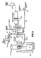
- a schematic illustration of a system for performing the method of this invention is shown.
- the apparatus employs a bulk source of polymeric material such as a bulk melter 10 containing heating means for liquifying a solid or semi-solid polymer material and pumping it from the tank.
- a bulk melter is shown in U. S. Patent No. 4,073,409 also assigned to the assignee of this invention and that description is incorporated herein by reference.
- the pump is a cartridge-type gear pump, however, any pump capable of providing sufficient pressure to pump the material from the bulk container is suitable. This could include a dual axis screw pump integrated with the disk mixer. Alternatively, hot melt could be provided from conventional, commercially available hot melt dispensers.
- the source of polymer material is of course not heated.
- the material to be foamed is conveyed through line 12, which may be a hose capable of conveying heated material under pressure, to the upstream end of a disk mixer 14 where it is injected into the mixer.
- the foaming gas is supplied to the disk mixer from a pressurized gas supply 15 through a gas line 16.
- a pressure regulator 18 and flow meter 20 in line 16 permit control of gas pressure and flow rate to the mixer 14.
- the gas may be supplied to the system through several alternative paths. One is to fill the mixer only partially full with polymer material and to fill the head space in the disk mixer over the polymer material with gas from line 16 (shown in solid) to a desired pressure whereupon in the mixer the polymeric material to be foamed entrains the gas from the head space on operation of the mixer to form the polymer/gas solution.
- An alternative gas flow path 16a (shown in dotted) is to meter gas bubbles into the line 12 supplying the polymeric material to the mixer 14 such that the gas and polymer enter the mixer together and completely fill it for placing the gas into solution in the polymer in the mixer.
- Another alternative 16b (also shown in dotted) is to have a porous end plate in the mixer and to supply gas bubbles through the porous end plate to the mixer 14, which is completely filled with polymer, and into the polymer. Any or these alternative methods may be used depending upon application; however, for purposes of illustration, supplying the foaming gas to the head space in the mixer 14 through line 16 is illustrated as one embodiment.
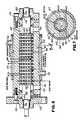
- the mixer 14 comprises a tubular housing 22 which is supported on a base 23 (shown in dotted in Fig. 2) in a substantially horizontal position and may be secured thereto by means of straps 25. Extending along the long axis of the housing 22 are a pair of substantially parallel shafts 24, 26. Upstream and downstream end caps 28 and 30, respectively, are secured to the respective opposite ends of the housing 22 by suitable means such as screws 32. The end caps 28 and 30 close the housing 22 ends and include suitable thrust bearings 34 and journals 36 for supporting the shafts in the end caps 28, 30 for rotation.
- one of the shafts 24 is driven by an electric motor 38.
- a constant rpm controller 40 can be used to control motor speed.
- a torque sensor 42 is used to sense and to control the level of material in the mixer since under constant processing conditions the torque to drive the shafts is directly related to the amount of material being processed.
- the drive shaft 24 includes a gear 44 which meshes with a like gear 46 on the adjacent driven shaft 26 such that on rotation of drive shaft 24 in one direction the driven shaft 26 rotates in the opposite direction.
- Each shaft 24, 26 includes a series of spaced, solid, flat disks 48 which are substantially perpendicular to the axis of the shafts 24, 26. As best seen in Figs. 2 and 3, the disks 48 intermesh or overlap one with another in the space between the two shafts 24, 26. Moreover, the disks extend substantially to the inner circumference 50 of the housing 22 creating a nip 51 therebetween. Operation of the drive motor 38 causes rotation of the shafts 24, 26 in opposite directions (shown by arrows in Fig. 2) which causes the overlapping faces of the intermeshing disks 48 to move with respect to one another and the circumference of the disks 48 to move with respect to the fixed housing interior 50.
- the polymeric material enters the housing 22 through a port 52 in the upstream end cap 28 of the housing 22.
- Line 16 is connected to port 52 by a suitable fitting (not shown).
- the foaming gas delivered to the housing through line 16 enters through an opening 54 in the housing wall 22.
- Line 16 is connected to opening 54 by a suitable pressurized hose fitting 55.
- the opening 54 could be placed in the material line 12 or end cap 28 or the foaming gas could be injected through a porous end plate into the material in the housing.
- the upstream disks 48 i.e., those disposed toward the end cap 28
- the downstream disks 48 are more closely spaced to one another than the downstream disks.
- This progressively increasing spacing of the intermeshing disks with respect to one another from upstream end to downstream end may provide some advantage in conveying material along the housing, particularly the more highly viscous materials.
- the disk spacing is critical, and this invention equally contemplates uniform spacing of the disks one with another.
- a material outlet in the form of a dip tube 56 extends through the housing wall 22 at the downstream end of the housing to a level of at least the center line of the shafts 24, 26.
- the dip tube 56 permits the polymer material having gas mixed in solution therewith and being under pressure in the housing to exit up the dip tube 56 and be conveyed to a dispensing nozzle. That is, in the embodiment shown in the drawings, the interior of the housing is filled to a level only to the top of the shafts with the space or head above the material being filled with foaming gas pressurized, e.g., to 300-350 psi. This pressure forces the material up the dip tube 56 and to the dispensing nozzle.
- dip tube 56 extends down to the centerline of the shafts, it is assured that gas in the head space does not inadvertently enter the dip tube which otherwise would interrupt the flow of material and cause sputtering.
- a sight glass 58 extending through the housing wall 22 can be used to visually observe the material to control the material level.
- torque sensor 42 can be used to sense and thus control the level of material in the housing.
- the housing can be completely filled with material as when gas is injected through lines 16a or 16b.
- the delivery pressure of the material to the mixer can be used to force the material/gas solution out of the mixer and to the dispensing nozzle.
- the housing 22 may be heated if desired, for example, in a temperature range of 70°F to 600°F by means of a band heater 60.
- Ports 62 may be provided along the length of the housing for insertion of thermocouples to measure the temperature of material within the housing.
- the rotating action of the intermeshing disks 48 is believed to apply a positive pressure to the viscous polymer which continuously pumps or forces the polymer from one end of the housing from the inlet 52 along the length of the housing 22 to the down stream end of the housing where it is discharged through the dip tube 56.
- the pumping pressure exerted on the viscous polymer by the intermeshing disks is greatest at the lower nip of the disks.
- a stator 64 in the bottom of the housing 22 having a cross section closely conforming to the radius of the disks at the lower nip of the disks prevents substantial bypassing of the material through the lower nip of the disks.
- the polymer tends to adhere to the surface of the disk and thus is picked up from the bottom of the housing and brought to the upper surface.
- gas is injected into a head space above the disk, the polymer brought to the surface is exposed to the gas creating fresh contacting surface for entraining the gas in the polymer.
- a "finger" of gas is drawn below the static fluid level following the flow of the fluid and with proper disk geometry mixes and dissolves in the polymer.
- the disk mixer both breaks up large bubbles of gas in the polymer and also entrains very small gas bubbles at the nip 51.
- rotation of the disks causes stretching of the gas bubbles generating surface area for dissolution to occur.
- rotation of the disks maintains laminar flow of the polymer material creating surface by separating the fluid along its flow lines. This generates maximum surface area with a minimum amount of work and thus minimum power consumption in the mixing operation.
- Figs. 1-4 show the orientation of the disk mixer to be one where the shafts on which the disks are mounted are substantially horizontally disposed, that particular orientation is not critical. It is of course necessary to have the shafts horizontal when a gas head space is created above the polymer material. However, where the foaming gas is mixed with the polymer either before or at the time of its injection into the disk mixer, the mixer can be on a vertical axis with either the upstream or downstream end at the higher elevation or in any orientation therebetween since the polymer material fills the interior in the housing. Moreover, the number of disks used and their diameter, thickness and spacing can be altered depending on the viscosity of the material being handled and desired throughput rates.
- the disk mixer is subject to a number of variations. For example, it is not necessary that both shafts be rotated. Rather, mixing has been successfully carried out by rotating only one of the shafts 24, 26 such that the disks on the rotating shaft intermesh with the fixed, non-rotating disks on the other shaft. This demonstrates that successful mixing can be accomplished by intermeshing disks, one set being on a rotor and the other on a stator. Also, the present invention contemplates a number of shafts (greater than the two shown in the Figures) carrying disks which intermesh with the disks on adjacent shafts. In accordance with the principles stated, some of these shafts may be operated as rotors and some as stators or all as rotors.
- a second stator be located within the housing 22 having a contour similar to that of stator 64 and opposite thereto. These stators are believed to reduce the presence of eddies and stagnant material areas that otherwise would decrease the efficiency of the mixing unit. Thus although desirable in this regard, they are not absolutely necessary for mixing.
- FIG. 5 of the drawings a schematic illustration of another system for performing the method of this invention is shown.
- This apparatus employs a pump 110 capable of delivering the polymeric material from a bulk source such as a bucket or barrel 111 at a metered rate from about 10 to 1,000 pounds per hour at a pressure normally in the range of 500 to 1,200 psig but of up to 5,000 psig without doing an undue amount of work on the polymeric material thus avoiding raising the polymer temperature.
- a suitable pump is a double acting piston pump driven by an air motor 113, such as a Johnstone pump.
- any pump capable of providing sufficient pressure to pump the material from the bulk container 111 is suitable.
- the pump 110 is fitted with a device such as a linear potentiometer 114 to generate a signal proportional to polymer flow rate.
- the material to be foamed is conveyed through line 116, which may be a hose capable of conveying liquid material under pressure, through an accumulator 117 to the upstream or inlet end 119 of a disk mixer 118 where it is injected into the mixer.
- line 116 which may be a hose capable of conveying liquid material under pressure
- the foaming gas is supplied to the disk mixer 118 from a pressurized gas supply through a gas line 120.
- a gas metering valve 122 and a differential pressure valve 124 in line 120 permit control of gas pressure and flow rate to the mixer 118 independent of system pressure and proportional to polymer flow rate.
- a suitable valve 122 is a Model 5850E Flow Controller manufactured by Brooks Instrument Division, Emerson Electric Co., Hatfield, Pennsylvania.
- the gas is supplied to the mixer 118 close to the polymer material inlet 119.
- a check valve 125 prevents flow of polymer material into line 120.
- the polymer and gas are introduced to the mixer 118 at an elevated pressure, e.g., 500 to 1,200 psig.
- the gas flow path 120 introduces gas bubbles into the mixer close to the line 116 supplying the polymeric material to the mixer 118 such that the gas and polymer enter the mixer together and completely fill it for placing the gas into solution in the polymer in the mixer.
- Mixer 118 is driven by a motor and reducer 126 controlled by a standard motor controller 128. At the downstream end of the mixer 118 is an outlet 130 through which the polymer/gas solution passes out of the mixer through a line 132 to a dispensing nozzle 134. The temperature of the polymer/gas solution exiting the mixer is monitored by a thermocouple 136.
- the temperature of the mixer may be controlled by circulating cooling water through a jacket 137 (Fig. 6) surrounding the mixer 118 as controlled by a valve 138 responsive to a valve input signal from the thermocouple 136.
- a jacket 137 FIG. 6
- the materials described above are unaffected by a temperature rise of up to 20°F and can withstand a 30 to 50°F temperature rise. Coolant can be used to maintain these parameters.
- the mixer 118 comprises a tubular housing or barrel 140 which is supported on a mount by means of bolts (not shown). Extending along the long axis of the housing 140 is a shaft 146. Downstream and upstream end caps 148 and 150, respectively, are secured to the respective opposite ends of the housing 140 by suitable means such as bolts 152. The end caps 148 and 150 close the housing 140 ends and include suitable thrust bearings 154 and journals 156 for supporting the shaft 146 for rotation.
- housing 140 Since the interior of housing 140 is under pressure and since some applications such as the foaming of hot melt adhesives takes place at elevated temperatures, e.g., 350°F or higher, the seals must be able to withstand these elevated pressures and temperatures without leaking. Alternatively, small grooves can be placed in the shaft 146 to pump material back to chamber or center core 147.
- the shaft 146 is driven by an electric motor through a reducer 126.
- a constant rpm controller 128 can be used to control motor speed.
- the shaft 146 is machined to provide a series of spaced disks 158 which are substantially perpendicular to the axis of the shaft 146.
- the disks 158 have a series of spaced teeth 160 on the outer circumference separated by slots 162.
- the teeth 160 extend substantially almost to the inner wall 164 of the housing 140 creating individual spaced compartments between the teeth 160, the slots 162, and the housing wall 164 while permitting rotation of the shaft and disks within the housing 140.
- Operation of the drive motor 126 causes rotation of the shaft 146 which in turn causes rotation of the spaced disks 158 and movement of the teeth 160 and slots 162 with respect to the fixed housing inner wall 164.
- the polymeric material enters the housing 140 through a port 119 in the upstream end of the housing communicating with the center bore 147 of housing 140.
- Line 116 is connected to port 119 by a suitable fitting (not shown).
- the foaming gas delivered to the housing through line 120 enters through an opening (not shown) in the housing wall close to port 119.
- Line 120 is connected to the opening by a suitable pressurized hose fitting.
- a material outlet port 130 extends through the housing wall 140 at the downstream end of the housing.
- the port 130 is connected with line 132 and permits the polymer material having gas mixed in solution and being under pressure in the housing 140 to exit the mixer 118 and be conveyed to the dispensing nozzle 134.
- the housing 140 may be cooled if desired, for example, by circulating cooling water through the space 170 between the jacket 137 and the outer wall of the housing 140. Ports 172, 174 may be provided for cooling water inlet and outlet, respectively. Alter technically, in applications requiring heating of the polymeric material, e.g., in foaming hot melts, the jacket 137 may be removed and band heaters applied for heating the housing 140 to a desired temperature.
- the gas and the polymeric material are introduced into the mixer 118 under a pressure in the range from about 500 to 1200 psi.
- the disks 158 are rotated at a speed of 50 to 200 rpm, preferably in the range of 100 to 200 rpm.
- the gas comes into contact with the rotating disks, several phenomena occur.
- the gas/polymer mixture continually enters and exits subsequent downstream disks as it passes through the housing bore 147, it is cut, sheared, and twisted to provide a high interfacial area between the gas and the polymer.
- the gas is thoroughly mixed and in solution with the polymer.
- the orientation of the mixer is one where the shaft on which the disks are mounted is substantially horizontally disposed, that particular orientation is not critical.
- the mixer could be on a vertical axis with either the upstream or downstream end at the higher elevation or in any orientation therebetween since the polymer material fills the interior of the housing.
- the specific disk mixer used in performing Examples I-V recited below was configured as shown in Figs. 1-4 and was formed of forged steel 4140 tubing 13.19 inches in length and 4.685 inches in diameter.
- the tubing had an external Watlow electric band tape heater permitting it to be heated in the range of 70°F to 600°F.
- Two shafts extended through the housing as shown in Fig. 3 of the drawings. Each shaft carried 11 solid steel disks 2.625 inches in diameter and 0.25 inches in thickness.
- the disks were spaced on the shafts to form three stages. In the first stage, the disks were 0.5 inches apart; in the second stage, they were 0.75 inches apart; and in the third stage, they were 1 inch apart.
- the disks were driven by an electric motor manufactured by Hampton Products Company, Inc.
- variable horsepower having a variable horsepower from 0 to 3. It was typically operated at less than 0.5 horsepower.
- the rpm's of the shaft could be varied from 0 to 175 rpm but were typically operated in 100 rpm area.
- the material was delivered to a nozzle for dispensing which varied between 1/16 and 3/16 inch in internal diameter and 3/4 and 11 ⁇ 2 inch in length depending on the material and pressures involved.
- Eastabond A-3 is a low molecular weight branched polyethylene-based hot melt adhesive composition manufactured by Eastman Chemical Company. Its viscosity, as measured by a Brookfield viscometer, was about 2,200 cps at 350°F.
- the material was supplied to the mixer at a pressure of 700 to 740 psig at an average flow rate into the mixer of 80 pounds per hour. Nitrogen gas at a temperature of 70°F and a pressure of 800 psig was added to the polymer stream upstream of the mixer (line 16a of Fig. 1) so that both polymer and gas entered the mixer through the polymer inlet 52.
- the mixer was operated at about 160 rpm shaft rotation.
- the material passed through the mixer and was dispensed through the dip tube to a dispensing nozzle.
- the temperature of the gas/polymer solution exiting the mixer was 350°F.
- the overall flow rate of material from the mixer was on the order of 80 pounds per hour.
- the resulting product was a continuous, creamy, very homogeneous foam with small bubbles contained therein.
- the foam ratio by volume ratio of volume of material occupied after foaming to volume occupied before foaming was 2.26:1. This example thus illustrates the foaming of a lower viscosity hot melt adhesive at 350°F to form a homogeneous adhesive foam.
- the apparatus essentially like that of Figs. 2-4 and used in Example I was operated for foaming an intermediate molecular weight branch polyethylene-based adhesive, Eastabond A-32, again manufactured by Eastman Chemical Company.
- This material which is a hot melt adhesive, had a viscosity on the order of 35,000 to 40,000 cps as measured by a Brookfield viscometer at 350°F. It was injected into the disk mixer at a temperature of 350°F and a pressure of 300 to 550 psig. The flow rate into the mixture was between 15 and 40 pounds per hour. Carbon dioxide at 70°F and 1,400 to 1,450 psig was metered into the polymer stream at a rate of .26 to .58 pounds per hour upstream of the mixer. This was accomplished by inserting a porous steel tube in the polymer material flow line to the mixer. The porous tube communicated with the source of gas under pressure. The polymer material stripped the gas bubbles off the surface of the porous tube as it flowed by.
- the material with foaming gas added then entered the mixer and passed therethrough with a flow rate from the mixer of 14 to 40 pounds per hour.
- the mixer was operated at 350°F and the material was dispensed from the top of the mixer to a 1/16 inch nozzle.
- the mixer was operated full so that there was no gas head in the mixer.
- the shafts were rotated at about 96 rpm.
- the resulting foam had a foam ratio by volume of between 3:1 and 7:1.
- the foam was homogeneous although it contained larger bubbles than in Example I. This example demonstrates the continuous production of polymeric foams from higher viscosity hot melt adhesives at good flow rates and good foam ratios.
- the polymer/gas solution was again dispensed through the top of the mixer to a 1/16 inch dispensing nozzle.
- the material flow rate from the mixer was 14 to 40 pounds per hour.
- the foam ratio of the material was about 5:1 to 8:1 by volume. Again the resulting product was a continuous homogeneous foam.
- the CO2 and He gas were supplied at a pressure of 250 psig and the N2 gas at 500 psig.
- the flow rates for CO2, N2 and He gas were on the order of 1%, .5% and .1% by weight of polymer, respectively.
- the polymer/gas solution was dispensed at a temperature of 415°F through the bottom of the mixer for CO2 and N2 gas and through the top for He.
- the foam ratios for CO2, N2 and He gas used were 2.5:1 to 4:1, 2:1 and 1.5:1, respectively.
- the resulting mixture in each case was an elastic foam which collapsed with time.
- the half life of the foam time to be reduced in volume by 50% was on the order of 15 to 30 minutes.
- the material was supplied to the mixer at a pressure of 250 psig and a flow rate of about 5 pounds per hour at a maximum temperature of 50°F. Nitrogen gas at a temperature of 70°F and a pressure of 250 psig was introduced into the head space above the polymer in the mixer. The material exited the top of the mixer at a temperature of less than 80°F. It was dispensed through a 1/16 inch nozzle. The flow rate from the mixer was on the order of 5 pounds per hour and the foam produced had a foam ratio of 2.2:1. The resulting product was a tough, resilient foam rubber having gas cells up to 1/16 inch in diameter. This example demonstrates the efficacy of the present apparatus and method of this invention in forming acceptable foams of relatively high viscosity polymer materials at acceptable throughputs with minimal and acceptable temperature rise of the polymer material.
- the high viscosity silicone materials such as Dow Corning 732 Silicone RTV was foamed at a horsepower requirement of only 0.12 and would result in a temperature rise of only 8.7°F at a throughput rate of 60 pounds per hour. It has been calculated by contrast that a paddle driven by a one horsepower motor would raise the temperature of the silicone RTV sealant well in excess of 100°F.
- a disk mixer as shown in Figs. 6 and 7 was built of 41L40 steel.
- the length of the bore 147 was 8 inches, and the bore 147 had a radius of 1.008 inches.
- the housing had an external water jacket 137 permitting it to be cooled in the range of 30 to 70°F. Polymer material inlet temperatures were in the range of 65°-70°F.
- the shaft 146 extended through the barrel 140, as shown in Fig. 6 of the drawings.
- the shaft diameter (2) was 1.5 inches.
- the shaft 146 included sixteen steel disks 2.0 inches in diameter and 0.25 inch in disk width (6).
- the groove width (7) between disks was 0.25 inch and the groove depth (9) was also 0.25 inch.
- Each disk had 15 teeth and 15 slots. Referring to Fig. 7, the slot depth (3) was 0.125 inch and the slot width (12) was 0.356 inch.
- the clearance (8) between the teeth 160 and the wall 164 was 0.008 inch. Fifteen percent of the disk circumference was comprised of the land area of
- the shaft was driven by an electric motor operated typically at about 0.25 horsepower.
- the shaft was typically rotated in the 100 to 200 rpm range. All materials were foamed with N2 gas.
- the polymer material and gas were introduced into the mixer at a pressure in the range of 500 to 1000 psi.
- the material was delivered to a nozzle for dispensing which varied between .060 and .125 inch in internal diameter and .5 and 3 inches in length depending on the material and pressures involved.
- Table II shows the results of foaming different commercially available polymers with the mixer shown in Figs. 5-7. In each case the resulting product was a continuous, creamy, very homogenous foam with small bubbles contained therein.
- the foams produced by this invention have a wide variety of uses. They may be injected and molded, used for adhesive applications, foamed in situ to seal openings, seams and cracks, or foamed in situ as part of a manufacturing process such as forming gaskets and seals in place.
- the advantages of the present invention can be additionally appreciated by recognizing that currently silicone RTV rubbers are foamed only by using expensive specialty ingredients and a platinum catalyst.
- the high cost of the material makes its uses extremely limited.
- the present invention on the other hand provides highly efficient and low cost foaming of polymeric materials for a wide variety of applications extending from hot melt adhesives through the high viscosity thermosetting sealants and caulkings.
- the apparatus disclosed and described above are illustrative of suitable apparatus for carrying out the present invention and that a wide variety of multiple shaft and disk configurations may be adopted depending on the polymer material being foamed and on the throughput rates desired. It will also be recognized that there may be a number of variations of a flat disk which also achieve laminar flow of the polymer as opposed to turbulent mixing, including a spoked-wheel configuration. However, those variations which nevertheless produce laminar flow are intended to be encompassed by the term "disk" used herein. It will be further recognized that the present invention can foam materials having viscosities from several thousand centipoises to 1,000,000 cps or more.
- the present invention finds particular applicability in foaming materials above 10,000 cps and typically above 50,000 cps where problems of inadequate mixing, unacceptable temperature rise, and reduced throughput arise and become increasingly acute.
Landscapes
- Engineering & Computer Science (AREA)
- Mechanical Engineering (AREA)
- Processing And Handling Of Plastics And Other Materials For Molding In General (AREA)
- Manufacture Of Porous Articles, And Recovery And Treatment Of Waste Products (AREA)
- Lining Or Joining Of Plastics Or The Like (AREA)
- Molding Of Porous Articles (AREA)
Applications Claiming Priority (2)
| Application Number | Priority Date | Filing Date | Title |
|---|---|---|---|
| US36871 | 1987-04-09 | ||
| US07/036,871 US4778631A (en) | 1985-10-02 | 1987-04-09 | Method and apparatus for foaming high viscosity polymer materials |
Publications (3)
| Publication Number | Publication Date |
|---|---|
| EP0286015A2 true EP0286015A2 (fr) | 1988-10-12 |
| EP0286015A3 EP0286015A3 (en) | 1989-09-13 |
| EP0286015B1 EP0286015B1 (fr) | 1992-06-03 |
Family
ID=21891124
Family Applications (1)
| Application Number | Title | Priority Date | Filing Date |
|---|---|---|---|
| EP88105241A Expired - Lifetime EP0286015B1 (fr) | 1987-04-09 | 1988-03-31 | Procédé et dispositif pour écumer des matériaux polymères à haute viscosité |
Country Status (6)
| Country | Link |
|---|---|
| US (1) | US4778631A (fr) |
| EP (1) | EP0286015B1 (fr) |
| JP (1) | JPH0815745B2 (fr) |
| AU (1) | AU611893B2 (fr) |
| CA (1) | CA1293347C (fr) |
| DE (1) | DE3871592T2 (fr) |
Cited By (5)
| Publication number | Priority date | Publication date | Assignee | Title |
|---|---|---|---|---|
| EP0843246A3 (fr) * | 1996-11-12 | 1998-06-17 | Linde Aktiengesellschaft | Regulateur de debit |
| EP0807503A3 (fr) * | 1996-05-17 | 1998-10-07 | TECHINT - Compagnia Tecnica Internazionale S.p.A. | Procédé de mélange en continu de polymères et dispositif associé à rotors partiellement tangentiels et partiellement s'engrènant mutuellement |
| GB2366797A (en) * | 2000-09-13 | 2002-03-20 | Procter & Gamble | Process for making foam component by pressurising/depressurising |
| EP3310543B1 (fr) | 2016-08-11 | 2018-09-26 | CeraCon GmbH | Dispositif et procédé de moussage d'un matériau visqueux |
| EP4063091A1 (fr) * | 2021-03-26 | 2022-09-28 | Starlinger & Co Gesellschaft m.b.H. | Dispositif et procédé de traitement thermique des fusions en matière thermoplastique |
Families Citing this family (66)
| Publication number | Priority date | Publication date | Assignee | Title |
|---|---|---|---|---|
| US5082142A (en) * | 1989-08-04 | 1992-01-21 | Nordson Corporation | Method and apparatus for applying non-chemically foamed multi-component curable polymers |
| US4983424A (en) * | 1989-08-04 | 1991-01-08 | Nordson Corporation | Method for forming a permanent foam coating by atomization onto a substrate |
| US5159894A (en) * | 1989-08-04 | 1992-11-03 | Nordson Corporation | Apparatus for forming a permanent foam coating by atomization onto a substrate |
| US5089190A (en) * | 1989-11-13 | 1992-02-18 | Nordson Corporation | Method and apparatus for hollow core extrusion of high viscosity materials |
| US5056034A (en) * | 1989-11-20 | 1991-10-08 | Nordson Corporation | Method and apparatus for controlling the gas content of foam materials |
| US5215253A (en) * | 1990-08-30 | 1993-06-01 | Nordson Corporation | Method and apparatus for forming and dispersing single and multiple phase coating material containing fluid diluent |
| US5207352A (en) * | 1991-04-19 | 1993-05-04 | Nordson Corporation | Method and apparatus for dispensing high viscosity fluid materials |
| US5423607A (en) * | 1991-05-03 | 1995-06-13 | Dolco Packaging Corp. | Method for blending diverse blowing agents |
| US5823669A (en) * | 1991-05-03 | 1998-10-20 | Lolco Packaging Corp. | Method for blending diverse blowing agents |
| US5197800A (en) * | 1991-06-28 | 1993-03-30 | Nordson Corporation | Method for forming coating material formulations substantially comprised of a saturated resin rich phase |
| US5318207A (en) * | 1992-04-20 | 1994-06-07 | Nordson Corporation | Method and apparatus for portable dispensing of foam material |
| US5421921A (en) * | 1992-07-08 | 1995-06-06 | Nordson Corporation | Segmented slot die for air spray of fibers |
| AU4668393A (en) * | 1992-07-08 | 1994-01-31 | Nordson Corporation | Apparatus and methods for applying discrete foam coatings |
| US5354378A (en) * | 1992-07-08 | 1994-10-11 | Nordson Corporation | Slot nozzle apparatus for applying coatings to bottles |
| US5418009A (en) * | 1992-07-08 | 1995-05-23 | Nordson Corporation | Apparatus and methods for intermittently applying discrete adhesive coatings |
| CA2098784A1 (fr) * | 1992-07-08 | 1994-01-09 | Bentley Boger | Installation et methodes pour deposer un revetement conforme sur des plaquettes de circuits electroniques |
| US5443796A (en) * | 1992-10-19 | 1995-08-22 | Nordson Corporation | Method and apparatus for preventing the formation of a solid precipitate in a coating material formulation |
| DE4235638A1 (de) * | 1992-10-22 | 1994-04-28 | Sonderhoff Ernst Fa | Verfahren zum Herstellen eines feinporigen Siliconschaumes |
| US5407267A (en) * | 1992-12-30 | 1995-04-18 | Nordson Corporation | Method and apparatus for forming and dispensing coating material containing multiple components |
| US5490726A (en) * | 1992-12-30 | 1996-02-13 | Nordson Corporation | Apparatus for proportioning two components to form a mixture |
| US5252627A (en) * | 1993-01-04 | 1993-10-12 | Dow Corning Corporation | Apparatus and method for blending and dispensing foamable, curable organosiloxane compositions |
| US5342858A (en) * | 1993-06-30 | 1994-08-30 | The Procter & Gamble Company | Elastomeric adhesive foam |
| US5389168A (en) * | 1993-06-30 | 1995-02-14 | The Procter & Gamble Company | Method of making an elastomeric adhesive foam and of elasticizing garments |
| EP0654300B1 (fr) * | 1993-09-28 | 1997-04-16 | Dow Corning Toray Silicone Co., Ltd. | Procédé pour mélanger un gaz dans un liquide hautement visqueux |
| US5407132A (en) * | 1993-10-20 | 1995-04-18 | Nordson Corporation | Method and apparatus for spraying viscous adhesives |
| US5556471A (en) * | 1994-05-17 | 1996-09-17 | Nordson Corporation | Method and apparatus for dispensing foam materials |
| US5480589A (en) * | 1994-09-27 | 1996-01-02 | Nordson Corporation | Method and apparatus for producing closed cell foam |
| US5472990A (en) * | 1994-11-10 | 1995-12-05 | Dennis Chemical Co., Inc. | Method and apparatus for nucleation of polyurethane foam which results in self-adhering microcellular foam |
| US5604300A (en) * | 1995-08-15 | 1997-02-18 | Halliburton Company | Crosslink test method |
| US7338980B2 (en) * | 1995-12-01 | 2008-03-04 | Sunstar Giken Kabushiki Kaisha | Method and apparatus for mixing a high-viscosity material into a gas |
| US6538040B1 (en) | 1995-12-01 | 2003-03-25 | Sunstar Giken Kabushiki Kaisha | Method and apparatus for mixing a high-viscosity material into a gas |
| US5874031A (en) * | 1995-12-01 | 1999-02-23 | Sunstar Engineering Inc. | Method of and apparatus for foaming a viscous material |
| US6884823B1 (en) * | 1997-01-16 | 2005-04-26 | Trexel, Inc. | Injection molding of polymeric material |
| DE69827938T2 (de) * | 1997-04-01 | 2005-05-25 | Sunstar Giken K.K., Takatsuki | Verfahren und gerät zum mischen eines gases mit einem hochviskosen material |
| US6471392B1 (en) | 2001-03-07 | 2002-10-29 | Holl Technologies Company | Methods and apparatus for materials processing |
| US7538237B2 (en) * | 1999-07-02 | 2009-05-26 | Kreido Laboratories | Process for high shear gas-liquid reactions |
| US6742774B2 (en) * | 1999-07-02 | 2004-06-01 | Holl Technologies Company | Process for high shear gas-liquid reactions |
| US6607099B2 (en) * | 1999-12-17 | 2003-08-19 | Illinois Tool Works Inc. | Air drive system |
| US6830806B2 (en) * | 2001-04-12 | 2004-12-14 | Kreido Laboratories | Methods of manufacture of electric circuit substrates and components having multiple electric characteristics and substrates and components so manufactured |
| EP1446222A2 (fr) * | 2001-09-13 | 2004-08-18 | Holl Technologies Company | Procedes et appareils d'echange d'energie thermique entre la surface d'un corps et un fluide d'echange thermique |
| US6787246B2 (en) | 2001-10-05 | 2004-09-07 | Kreido Laboratories | Manufacture of flat surfaced composites comprising powdered fillers in a polymer matrix |
| US7098360B2 (en) * | 2002-07-16 | 2006-08-29 | Kreido Laboratories | Processes employing multiple successive chemical reaction process steps and apparatus therefore |
| EP1540302A4 (fr) * | 2002-09-11 | 2008-05-07 | Kreido Lab | Procedes et appareil permettant d'effectuer un melange et une reaction a cisaillement eleve de materiaux |
| US6938687B2 (en) * | 2002-10-03 | 2005-09-06 | Holl Technologies Company | Apparatus for transfer of heat energy between a body surface and heat transfer fluid |
| WO2004060628A1 (fr) * | 2003-01-07 | 2004-07-22 | Sunstar Giken Kabushiki Kaisha | Materiau pateux durcissant a une composante destine a etre utilise dans une machine de moussage |
| US7059760B2 (en) * | 2003-04-02 | 2006-06-13 | Bostik, Inc. | Method of post mixing additives to hot melt adhesives |
| EP1654072A4 (fr) * | 2003-07-14 | 2007-10-03 | Nordson Corp | Appareil et procede permettant la distribution de quantites discretes de matiere visqueuse |
| US20050094482A1 (en) * | 2003-10-31 | 2005-05-05 | Nordson Corporation | Method and apparatus for producing closed cell foam |
| US20050205009A1 (en) * | 2004-02-26 | 2005-09-22 | Illinois Tool Works Inc. | Swivel joint assembly for interconnecting hot melt adhesive supply hose and applicator components |
| US7717059B2 (en) * | 2005-06-15 | 2010-05-18 | Spraying Systems Co. | Liquid adhesive dispensing system |
| CA2621491C (fr) * | 2005-09-13 | 2011-01-18 | Bayone Urethane Systems, Llc | Melangeur helicoidal dynamique et appareil de melange associe |
| JP4397390B2 (ja) * | 2006-10-20 | 2010-01-13 | 行雄 土屋 | パッキン付き製造蓋の製造方法及び製造装置 |
| US7703705B2 (en) | 2007-02-16 | 2010-04-27 | Nordson Corporation | Apparatus and method for dispensing a mixture of a gas and a fluid material |
| DE102007020095A1 (de) * | 2007-04-26 | 2008-10-30 | Nordson Corporation, Westlake | Vorrichtung und Verfahren zum Schaumauftrag auf Substrate mit großer Breite |
| US20090236025A1 (en) * | 2008-03-24 | 2009-09-24 | Nordson Corporation | Apparatus and methods for producing foamed materials |
| CN102959026B (zh) | 2010-06-30 | 2014-12-24 | 3M创新有限公司 | (甲基)丙烯酰压敏泡沫粘合剂 |
| DE102010060604B4 (de) * | 2010-11-16 | 2013-01-31 | Puffe Engineering Gmbh | Schaumpumpe und Verfahren zum Aufschäumen von flüssigen Medien |
| TW201345828A (zh) * | 2011-11-07 | 2013-11-16 | Graco Minnesota Inc | 用於施配閥之直接空氣馬達驅動幫浦 |
| US10058825B2 (en) | 2014-12-12 | 2018-08-28 | Nordson Corporation | Foam mixing system and methods |
| EP3450024B1 (fr) * | 2017-08-30 | 2023-02-01 | Wagner International Ag | Installation de dosage et d'application pour un matériau polymère durci sous l'effet de l'humidité |
| JP7548929B2 (ja) * | 2019-03-15 | 2024-09-10 | ノードソン コーポレーション | ホットメルト接着剤フォーム吐出システム |
| JP7454793B2 (ja) * | 2020-02-21 | 2024-03-25 | パナソニックIpマネジメント株式会社 | ヘアケア装置 |
| CN112497550B (zh) * | 2020-11-13 | 2022-04-22 | 安吉阿丽拉电子商务有限公司 | 一种色母粒加工用搅拌装置 |
| WO2024215590A1 (fr) * | 2023-04-10 | 2024-10-17 | Vaproshield Llc | Procédé de fabrication d'un adhésif sensible à la pression qui fournit une perméabilité à la vapeur substantielle, et systèmes associés |
| WO2025245446A1 (fr) * | 2024-05-24 | 2025-11-27 | Nordson Corporation | Technologie associée à un dispositif de commande de densité de mousse à actionnement électrique |
| DE102024118282A1 (de) * | 2024-06-27 | 2025-12-31 | Focke Meler Germany GmbH | Schaumpumpe zum Aufschäumen von flüssigen Medien |
Family Cites Families (15)
| Publication number | Priority date | Publication date | Assignee | Title |
|---|---|---|---|---|
| US2397818A (en) * | 1944-11-06 | 1946-04-02 | American Anode Inc | Method and apparatus for concentrating colloidal dispersions |
| GB622159A (en) * | 1946-10-25 | 1949-04-27 | Wingfoot Corp | Frothing mechanism |
| GB646591A (en) * | 1948-03-03 | 1950-11-22 | Earle Thomas Oakes | Improvements relating to mixing devices |
| CH319589A (de) * | 1953-03-12 | 1957-02-28 | Spumalit Anstalt | Einrichtung zur kontinuierlichen Herstellung von härtbarem Schaumstoff |
| US2934325A (en) * | 1955-08-08 | 1960-04-26 | Hedemora Verkst Er Ab | Contacting apparatus for gases and liquids |
| BE565130A (fr) * | 1957-02-25 | |||
| LU37746A1 (fr) * | 1958-10-03 | |||
| US3042264A (en) * | 1959-10-01 | 1962-07-03 | Pyles Ind Inc | Demand mixing and dispensing machine |
| US3211148A (en) * | 1962-05-25 | 1965-10-12 | Jr John E Galajda | Rotary disk oxygenator and heater |
| US3171725A (en) * | 1962-07-23 | 1965-03-02 | Eddy W Eckey | Method and apparatus for contacting liquids and gases |
| US3348829A (en) * | 1963-12-18 | 1967-10-24 | Allis Chalmers Mfg Co | Aerator |
| US3353337A (en) * | 1964-09-14 | 1967-11-21 | Allis Chalmers Mfg Co | Two-phase contactor |
| US3402919A (en) * | 1965-07-15 | 1968-09-24 | Haglund Gustaf | Contacting apparatus for gases and liquids |
| GB1223275A (en) * | 1967-04-05 | 1971-02-24 | Kanegafuchii Kagaku Kogyo Kabu | Improvements in and relating to extruders |
| CH458713A (de) * | 1967-06-20 | 1968-06-30 | Tsniitmash | Durchlauf-Mischer für die Zubereitung von Schaummischungen |
-
1987
- 1987-04-09 US US07/036,871 patent/US4778631A/en not_active Expired - Lifetime
-
1988
- 1988-03-16 CA CA000561672A patent/CA1293347C/fr not_active Expired - Lifetime
- 1988-03-31 DE DE8888105241T patent/DE3871592T2/de not_active Expired - Fee Related
- 1988-03-31 EP EP88105241A patent/EP0286015B1/fr not_active Expired - Lifetime
- 1988-04-08 AU AU14407/88A patent/AU611893B2/en not_active Ceased
- 1988-04-09 JP JP63086294A patent/JPH0815745B2/ja not_active Expired - Fee Related
Cited By (8)
| Publication number | Priority date | Publication date | Assignee | Title |
|---|---|---|---|---|
| EP0807503A3 (fr) * | 1996-05-17 | 1998-10-07 | TECHINT - Compagnia Tecnica Internazionale S.p.A. | Procédé de mélange en continu de polymères et dispositif associé à rotors partiellement tangentiels et partiellement s'engrènant mutuellement |
| CN1108907C (zh) * | 1996-05-17 | 2003-05-21 | 波米尼公司 | 连续混合橡胶的带部分相切,穿插旋转件的机器 |
| EP0843246A3 (fr) * | 1996-11-12 | 1998-06-17 | Linde Aktiengesellschaft | Regulateur de debit |
| GB2366797A (en) * | 2000-09-13 | 2002-03-20 | Procter & Gamble | Process for making foam component by pressurising/depressurising |
| EP3310543B1 (fr) | 2016-08-11 | 2018-09-26 | CeraCon GmbH | Dispositif et procédé de moussage d'un matériau visqueux |
| US10618198B2 (en) | 2016-08-11 | 2020-04-14 | Ceracon Gmbh | Device and method for foaming a viscous material |
| EP4063091A1 (fr) * | 2021-03-26 | 2022-09-28 | Starlinger & Co Gesellschaft m.b.H. | Dispositif et procédé de traitement thermique des fusions en matière thermoplastique |
| WO2022200051A3 (fr) * | 2021-03-26 | 2022-11-17 | Starlinger & Co Gesellschaft M.B.H. | Dispositif et procédé de traitement thermique de matières thermoplastiques fondues |
Also Published As
| Publication number | Publication date |
|---|---|
| JPH0815745B2 (ja) | 1996-02-21 |
| EP0286015B1 (fr) | 1992-06-03 |
| DE3871592D1 (de) | 1992-07-09 |
| DE3871592T2 (de) | 1993-01-21 |
| CA1293347C (fr) | 1991-12-24 |
| AU1440788A (en) | 1988-10-13 |
| JPS63264327A (ja) | 1988-11-01 |
| US4778631A (en) | 1988-10-18 |
| EP0286015A3 (en) | 1989-09-13 |
| AU611893B2 (en) | 1991-06-27 |
Similar Documents
| Publication | Publication Date | Title |
|---|---|---|
| US4778631A (en) | Method and apparatus for foaming high viscosity polymer materials | |
| KR0145719B1 (ko) | 자동차 차체 시임용 독립기포 발포체 밀봉과 그 제조방법 및 장치 | |
| CA1102227A (fr) | Mousse adhesive thermoplastique thermofusible | |
| US4493286A (en) | Method and apparatus for applying a multi-component adhesive | |
| EP0220450B1 (fr) | Méthode et appareil pour faire mousser des matériaux polymères à viscosité élevée | |
| CA1085098A (fr) | Mousse adhesive thermoplastique | |
| KR100292096B1 (ko) | 밀폐셀기포제조방법및장치 | |
| US3630689A (en) | Apparatus for reacting and devolatilizing prepolymer and like materials | |
| GB1562562A (en) | Hot melt thermoplastic adhesive foam system | |
| JPH04276407A (ja) | 自動車タイヤ、駆動ベルト、コンベヤベルト並びに工業ゴム製品のためのゴム基礎混合物とゴム仕上げ混合物を1台の混合装置で1段階的にかつ連続的に製造するための方法と装置 | |
| US5851291A (en) | Chemical foaming machine and mixing apparatus | |
| US20050094482A1 (en) | Method and apparatus for producing closed cell foam | |
| EP0463759A2 (fr) | Procédé de production de mousse thermoplastique | |
| US3368799A (en) | Method and apparatus for lubricating gear pumps | |
| WO1994011096A1 (fr) | Appareil de melange de fluides | |
| JP2009511269A (ja) | 液状着色材を混合するための装置及び方法、並びに液状着色材によってプラスチックを着色するための方法 | |
| US4765745A (en) | Apparatus for dosing and mixing solids and liquids to form a low viscosity suspension | |
| JP3482309B2 (ja) | 高粘度材料の発泡方法及び装置 | |
| EP0614812B1 (fr) | Ensemble de buse mélangeur | |
| JPH08229939A (ja) | 二成分発泡材料を配量する方法および装置 | |
| JP3851895B2 (ja) | 高粘度材料の発泡方法及び装置 | |
| EP0974391B1 (fr) | Procede permettant d'incorporer du gaz a un materiau a viscosite elevee et dispositif afferent | |
| US7338980B2 (en) | Method and apparatus for mixing a high-viscosity material into a gas | |
| GB2047810A (en) | Rotary pumps | |
| JPH02233216A (ja) | 充実質乃至気泡質プラスチツクの製造に際し少なくとも1種の成分にガスを充填する方法 |
Legal Events
| Date | Code | Title | Description |
|---|---|---|---|
| PUAI | Public reference made under article 153(3) epc to a published international application that has entered the european phase |
Free format text: ORIGINAL CODE: 0009012 |
|
| AK | Designated contracting states |
Kind code of ref document: A2 Designated state(s): BE CH DE FR GB IT LI NL SE |
|
| PUAL | Search report despatched |
Free format text: ORIGINAL CODE: 0009013 |
|
| AK | Designated contracting states |
Kind code of ref document: A3 Designated state(s): BE CH DE FR GB IT LI NL SE |
|
| 17P | Request for examination filed |
Effective date: 19890922 |
|
| 17Q | First examination report despatched |
Effective date: 19910315 |
|
| GRAA | (expected) grant |
Free format text: ORIGINAL CODE: 0009210 |
|
| AK | Designated contracting states |
Kind code of ref document: B1 Designated state(s): BE CH DE FR GB IT LI NL SE |
|
| ITF | It: translation for a ep patent filed | ||
| ET | Fr: translation filed | ||
| REF | Corresponds to: |
Ref document number: 3871592 Country of ref document: DE Date of ref document: 19920709 |
|
| PLBE | No opposition filed within time limit |
Free format text: ORIGINAL CODE: 0009261 |
|
| STAA | Information on the status of an ep patent application or granted ep patent |
Free format text: STATUS: NO OPPOSITION FILED WITHIN TIME LIMIT |
|
| 26N | No opposition filed | ||
| EAL | Se: european patent in force in sweden |
Ref document number: 88105241.9 |
|
| REG | Reference to a national code |
Ref country code: GB Ref legal event code: IF02 |
|
| PGFP | Annual fee paid to national office [announced via postgrant information from national office to epo] |
Ref country code: FR Payment date: 20040227 Year of fee payment: 17 Ref country code: CH Payment date: 20040227 Year of fee payment: 17 |
|
| PGFP | Annual fee paid to national office [announced via postgrant information from national office to epo] |
Ref country code: NL Payment date: 20040317 Year of fee payment: 17 |
|
| PGFP | Annual fee paid to national office [announced via postgrant information from national office to epo] |
Ref country code: SE Payment date: 20040401 Year of fee payment: 17 |
|
| PGFP | Annual fee paid to national office [announced via postgrant information from national office to epo] |
Ref country code: BE Payment date: 20040506 Year of fee payment: 17 |
|
| PGFP | Annual fee paid to national office [announced via postgrant information from national office to epo] |
Ref country code: GB Payment date: 20040507 Year of fee payment: 17 |
|
| PGFP | Annual fee paid to national office [announced via postgrant information from national office to epo] |
Ref country code: DE Payment date: 20040512 Year of fee payment: 17 |
|
| PG25 | Lapsed in a contracting state [announced via postgrant information from national office to epo] |
Ref country code: LI Free format text: LAPSE BECAUSE OF NON-PAYMENT OF DUE FEES Effective date: 20050331 Ref country code: IT Free format text: LAPSE BECAUSE OF NON-PAYMENT OF DUE FEES;WARNING: LAPSES OF ITALIAN PATENTS WITH EFFECTIVE DATE BEFORE 2007 MAY HAVE OCCURRED AT ANY TIME BEFORE 2007. THE CORRECT EFFECTIVE DATE MAY BE DIFFERENT FROM THE ONE RECORDED. Effective date: 20050331 Ref country code: GB Free format text: LAPSE BECAUSE OF NON-PAYMENT OF DUE FEES Effective date: 20050331 Ref country code: CH Free format text: LAPSE BECAUSE OF NON-PAYMENT OF DUE FEES Effective date: 20050331 Ref country code: BE Free format text: LAPSE BECAUSE OF NON-PAYMENT OF DUE FEES Effective date: 20050331 |
|
| PG25 | Lapsed in a contracting state [announced via postgrant information from national office to epo] |
Ref country code: SE Free format text: LAPSE BECAUSE OF NON-PAYMENT OF DUE FEES Effective date: 20050401 |
|
| BERE | Be: lapsed |
Owner name: *NORDSON CORP. Effective date: 20050331 |
|
| PG25 | Lapsed in a contracting state [announced via postgrant information from national office to epo] |
Ref country code: NL Free format text: LAPSE BECAUSE OF NON-PAYMENT OF DUE FEES Effective date: 20051001 Ref country code: DE Free format text: LAPSE BECAUSE OF NON-PAYMENT OF DUE FEES Effective date: 20051001 |
|
| REG | Reference to a national code |
Ref country code: CH Ref legal event code: PL |
|
| EUG | Se: european patent has lapsed | ||
| GBPC | Gb: european patent ceased through non-payment of renewal fee |
Effective date: 20050331 |
|
| PG25 | Lapsed in a contracting state [announced via postgrant information from national office to epo] |
Ref country code: FR Free format text: LAPSE BECAUSE OF NON-PAYMENT OF DUE FEES Effective date: 20051130 |
|
| NLV4 | Nl: lapsed or anulled due to non-payment of the annual fee |
Effective date: 20051001 |
|
| REG | Reference to a national code |
Ref country code: FR Ref legal event code: ST Effective date: 20051130 |
|
| BERE | Be: lapsed |
Owner name: *NORDSON CORP. Effective date: 20050331 |