EP0286024B1 - Surfaces d'étanchéité d'une pompe de caloporteur d'un réacteur ayant un revêtement en nitrure de titane - Google Patents
Surfaces d'étanchéité d'une pompe de caloporteur d'un réacteur ayant un revêtement en nitrure de titane Download PDFInfo
- Publication number
- EP0286024B1 EP0286024B1 EP88105262A EP88105262A EP0286024B1 EP 0286024 B1 EP0286024 B1 EP 0286024B1 EP 88105262 A EP88105262 A EP 88105262A EP 88105262 A EP88105262 A EP 88105262A EP 0286024 B1 EP0286024 B1 EP 0286024B1
- Authority
- EP
- European Patent Office
- Prior art keywords
- coating
- titanium nitride
- pump
- sealing assembly
- runner
- Prior art date
- Legal status (The legal status is an assumption and is not a legal conclusion. Google has not performed a legal analysis and makes no representation as to the accuracy of the status listed.)
- Expired - Lifetime
Links
Images

Classifications
-
- G—PHYSICS
- G21—NUCLEAR PHYSICS; NUCLEAR ENGINEERING
- G21C—NUCLEAR REACTORS
- G21C19/00—Arrangements for treating, for handling, or for facilitating the handling of, fuel or other materials which are used within the reactor, e.g. within its pressure vessel
- G21C19/02—Details of handling arrangements
- G21C19/04—Means for controlling flow of coolant over objects being handled; Means for controlling flow of coolant through channel being serviced, e.g. for preventing "blow-out"
-
- F—MECHANICAL ENGINEERING; LIGHTING; HEATING; WEAPONS; BLASTING
- F16—ENGINEERING ELEMENTS AND UNITS; GENERAL MEASURES FOR PRODUCING AND MAINTAINING EFFECTIVE FUNCTIONING OF MACHINES OR INSTALLATIONS; THERMAL INSULATION IN GENERAL
- F16J—PISTONS; CYLINDERS; SEALINGS
- F16J15/00—Sealings
- F16J15/16—Sealings between relatively-moving surfaces
- F16J15/34—Sealings between relatively-moving surfaces with slip-ring pressed against a more or less radial face on one member
- F16J15/3496—Sealings between relatively-moving surfaces with slip-ring pressed against a more or less radial face on one member use of special materials
-
- F—MECHANICAL ENGINEERING; LIGHTING; HEATING; WEAPONS; BLASTING
- F04—POSITIVE - DISPLACEMENT MACHINES FOR LIQUIDS; PUMPS FOR LIQUIDS OR ELASTIC FLUIDS
- F04D—NON-POSITIVE-DISPLACEMENT PUMPS
- F04D29/00—Details, component parts, or accessories
- F04D29/08—Sealings
- F04D29/10—Shaft sealings
- F04D29/12—Shaft sealings using sealing-rings
- F04D29/126—Shaft sealings using sealing-rings especially adapted for liquid pumps
-
- Y—GENERAL TAGGING OF NEW TECHNOLOGICAL DEVELOPMENTS; GENERAL TAGGING OF CROSS-SECTIONAL TECHNOLOGIES SPANNING OVER SEVERAL SECTIONS OF THE IPC; TECHNICAL SUBJECTS COVERED BY FORMER USPC CROSS-REFERENCE ART COLLECTIONS [XRACs] AND DIGESTS
- Y02—TECHNOLOGIES OR APPLICATIONS FOR MITIGATION OR ADAPTATION AGAINST CLIMATE CHANGE
- Y02E—REDUCTION OF GREENHOUSE GAS [GHG] EMISSIONS, RELATED TO ENERGY GENERATION, TRANSMISSION OR DISTRIBUTION
- Y02E30/00—Energy generation of nuclear origin
- Y02E30/30—Nuclear fission reactors
Definitions
- the present invention relates to the use of a titanium nitride coating as a barrier layer or final coating on shaft seal surfaces in a nuclear reactor coolant pump, as it is known by EP-A- 0 203 377.
- a reactor coolant system In pressurized water nuclear power plants, a reactor coolant system is used to transport heat from the reactor core to steam generators for the production of steam. The steam is then used to drive a turbine generator.
- the reactor coolant system includes a plurality of separate cooling loops, each connected to the reactor core and containing a steam generator and a reactor coolant pump.
- the reactor coolant pump typically is a vertical, single stage, centrifugal pump designed to move large volumes of reactor coolant at high temperatures and pressures.
- the pump basically includes three general sections form bottom to top -- hydraulic, shaft seal and motor sections.
- the lower hydraulic section includes an impeller mounted on the lower end of a pump shaft which is operable within the pump casing to pump reactor coolant about the respective loop.
- the upper motor section includes a motor which is coupled to drive the pump shaft.
- the middle shaft seal section includes three tandem sealing assemblies --lower primary, middle secondary, and upper tertiary sealing assemblies. The sealing assemblies are located concentric to, and near the top end of, the pump shaft and their combined purpose is to provide for zero reactor coolant leakage along the pump shaft to the containment atmosphere during normal operating condition.
- the pump shaft seals constitute the main problem area for the reactor coolant pumps and significantly contribute to the utilization factor in nuclear power plants.
- the seals must be capable of breaking down the high system pressure safely.
- the tandem arrangement of three seals is used to break down the pressure, with the lower main seal absorbing most of the pressure drop.
- the lower primary sealing assembly is the main seal of the pump. It is typically a hydrostatic, "film-riding", controlled leakage seal whose primary components are an annular runner which rotates with the pump shaft and a non-rotating seal ring which remains stationary with the pump housing. Whereas the components of the lower primary sealing assembly are not intended to contact or rub together, corresponding components of the middle and upper sealing assemblies, a rotating runner and non-rotating seal ring, provide contacting or rubbing seals.
- the runner components of the rub-type sealing assemblies have been composed of a stainless steel substrate having an outer coating of chromium carbide on the surface of the runner components which rubs against the seal ring. Such coating has proven to be less than satisfactory. Blistering has been observed to occur on chromium carbide coated runners.
- Underlying the present invention is the recognition that blistering has been caused by contact with corrosive materials making up the nuclear water chemistry employed in nuclear reactors, such as chlorine or sulfur bearing compounds. These corrosive materials penetrate through the pores of the chromium carbide coating to the stainless steel/coating interface. Hydrogen gas formation caused by the corrosive mechanism then results eventually in a spalling, or blistering, of the coating's surface.
- the present invention resides in a pump having a shaft and a housing containing pressurized fluid, a rubbing-type sealing assembly for sealably and rotatably mounting said shaft within said housing, said sealing assembly having an annular runner circumscribing and mounted around said shaft for rotation therewith, an annular seal ring circumscribing and mounted within said housing in non-rotational relationship thereto, wherein said runner and seal ring have surfaces facing and in rubbing contact with one another, said sealing assembly characterized by a coating of titanium nitride incorporated on at least one of said surfaces.
- the coating of titanium nitride is deposited as an outer layer on the one surface.
- the coating of titanium nitride is deposited as an inner barrier layer upon the one surface and the assembly further comprises a coating of chromium carbide deposited as an outer layer on the coating of titanium nitride.
- the coating of titanium nitride can be incorporated on either or both surfaces of the seal ring and runner.
- the coating of titanium nitride can be used as a barrier layer or final coating surface on reactor coolant pump seal inserts and runners of rub-type seals.
- This coating will supply a wear surface resistant to the carbon graphitar seal ring contacting the runner face surface.
- the coating provides a wear resistant surface on which a secondary teflon channel seal will ride. Greater wear resistance increases the lifetime of the seals, and thereby the reliability of the overall system.
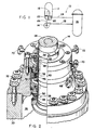
- the cooling loop 10 includes a steam generator 12 and a reactor coolant pump 14 serially connected in a closed coolant flow circuit with a nuclear reactor core 16.
- the steam generator 12 includes primary tubes 18 communicating with inlet and outlet plenums 20, 22 of the generator.
- the inlet plenum 20 of the steam generator 12 is connected in flow communication with the outlet of the reactor core 16 for receiving hot coolant therefrom along flow path 24 of the closed flow circuit.
- the outlet plenum 22 of the steam generator 12 is connected in flow communication with an inlet section side of the reactor coolant pump 14 along flow path 26 of the closed flow circuit.
- the outlet pressure side of the reactor coolant pump 14 is connected in flow communication with the inlet of the reactor core 16 for feeding cold coolant thereto along flow path 28 of the closed flow circuit.
- the coolant pump 14 pumps the coolant under high pressure about the closed flow circuit.
- hot coolant emanating from the reactor core 16 is conducted to the inlet plenum 20 of the steam generator 12 and to the primary tubes 18 in communication therewith. While in the primary tubes 18, the hot coolant flows in heat exchange relationship with cool feedwater supplied to the steam generator 12 via conventional means (not shown).
- the feedwater is heated and portions thereof changed to steam for use in driving a turbine generator (not shown).
- the coolant whose temperature has been reduced by the heat exchange, is then recirculated to the reactor core 16 via the coolant pump 14.
- the reactor coolant pump 14 must be capable of moving large volumes of reactor coolant at high temperatures and pressures about the closed flow circuit. Although the temperature of the coolant flowing from the steam generator 12 to the pump 14 after heat exchange has been cooled substantially below the temperature of the coolant flowing to the steam generator 12 from the reactor core 16 before heat exchange, its temperature is still relatively high, being typically about 288C. The coolant pressure produced by the pump is typically about 17.5 MPa.
- the reactor coolant pump 14 generally includes a pump housing 30 which terminates at one end in a seal housing 32.
- the pump 14 also includes a pump shaft 34 extending centrally of the housing 30 and being sealingly and rotatably mounted within the seal housing 32.
- the bottom portion of the pump shaft 34 is connected to an impeller, while a top portion thereof is connected to a high-horsepower, induction-type electric motor.
- the impeller within the interior 36 of the housing 30 circulates the coolant flowing through the pump housing 30 at pressures from ambient to approximately 17.5 MPa. This pressurized coolant applies an upwardly directed, hydrostatic load upon the shaft 34 since the upper portion of the seal housing 32 is surrounded by the ambient atmosphere.
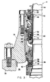
- tandemly-arranged lower primary, middle secondary, and upper tertiary sealing assemblies 38, 40, 42 are provided in the positions illustrated in Figs. 2 and 3 about the pump shaft 34 and within the pump housing 30.
- the lower primary sealing assembly 38 which performs most of the pressure sealing is of the non-contacting hydrostatic type, whereas the middle secondary and upper tertiary sealing assemblies 40, 42 are of the contacting or rubbing mechanical type.
- Each of the sealing assemblies 38, 40, 42 of the pump 14 generally includes a respective annular runner 44, 46, 48 which is mounted to the pump shaft 34 for rotation therewith and a respective annular seal ring 50, 52, 54 which is stationarily mounted within the seal housing 32.
- the respective runners 44, 46, 48 and seal rings 50, 52, 54 have top and bottom end surfaces 56, 58, 60 and 62, 64, 66 which face one another.
- the facing surfaces 56, 62 of the runner 44 and seal ring 50 of the lower primary sealing assembly 38 normally do not contact one another but instead a film of fluid normally flows between them.
- the facing surfaces 58, 64 and 60, 66 of the runners and seal rings 46, 52 and 48, 54 of the middle secondary and upper tertiary sealing assemblies 40 and 42 normally contact or rub against one another.
- the seal housing 32 includes a primary leakoff port 68, and secondary leakoff ports 70, which accommodate coolant fluid leakoff from secondary and tertiary sealing assemblies 40, 42.
- the present invention is directed to either one of the rubbing-type secondary or tertiary sealing assemblies 40, 42.
- a coating 72 of titanium nitride having a thickness within the range of about 0.0005 to 0.00075 cm, is preferably incorporated on at least one of the facing surfaces 58, 60 of the respective runners 46, 48 of the assemblies 40 and 42.
- the coating 72 of titanium nitride is illustrated deposited as an outer hardface layer within a groove 73 formed on the top facing surface 58 of the runner 46 of the middle sealing assembly 40.
- the coating 72 of titanium nitride provides a low-friction, high-wear surface which can withstand the corrosive compounds in nuclear water chemistry.
- the substrate material of the runners 46, 48 is preferably stainless steel, such as 304, 316 or 410 types.
- the substrate material of the seal rings 52, 54 is graphitar-114 and thus would not be coated or treated with titanium nitride.
- the titanium nitride could be deposited on the bottom facing surface 64 of the seal ring 52 rather than on the top facing surface 58 of runner 46 as illustrated, or, in the alternative, the titanium nitride could be deposited on both the bottom facing surface 64 of seal ring 52 and the top facing surface 58 of runner 46.
- the titanium nitride coating 72 can be deposited by any suitable method, such as chemical vapor deposition or physical vapor deposition.
- the coating 72 of titanium nitride can be deposited as an inner passivating barrier layer upon the top facing surface 58 of the runner 46.
- a coating 76 of chromium carbide or other hardface material having a thickness within the range of about 0.015 to 0.020 cm, can be deposited as an outer hardface layer on the coating 72 of titanium nitride.
- the pair of coatings 72, 76 just as equally could have been deposited on the bottom facing surface 64 of the seal ring 52 or on each of the surfaces 64, 58 of both the ring 52 and runner 46 if the seal ring 52 was not made of graphitar-114, but rather of stainless steel material like the runner 46.
- the chromium carbide coating 76 can be deposited by any suitable method, such as detonation gun coating.
- the middle or upper sealing assemblies 40, 42 of the pump thus has at least one rubbing surface which incorporates the coating of titanium nitride that is highly resistant to the blistering phenomenon observed heretofore on chromium carbide coated seal surfaces.
- Titanium nitride coatings being non-porous, substantially eliminate the problem of blistering. Over two thousand hours of testing have demonstrated their resistance to corrosion in nuclear grade water containing sulfur and chlorine contaminants. In contrast detonation gun coatings of chromium carbide have blistered severely after only five hundred hours in the same corrosive environment.
- the titanium nitride coating can be applied as either the actual wear/corrosion resistant hardface coating, or as a passivating layer deposited on the surface of the stainless steel substrate prior to its being further treated with detonation gun deposited chromium carbide or other hardface coatings.
- the coating of titanium nitride can be used as a barrier layer or final coating surface on reactor coolant pump seal surfaces of the rubbing-type. This coating when applied on the runner face surface will supply a wear surface resistant to the carbon graphitar seal ring contacting the runner.
Landscapes
- Engineering & Computer Science (AREA)
- General Engineering & Computer Science (AREA)
- Mechanical Engineering (AREA)
- Physics & Mathematics (AREA)
- Plasma & Fusion (AREA)
- High Energy & Nuclear Physics (AREA)
- Structures Of Non-Positive Displacement Pumps (AREA)
Claims (5)
- Dans une pompe (14) comprenant un arbre (34) et un carter (32) renfermant un fluide sous pression, un assemblage (40, 42) d'étanchéité du type à frottement servant au montage étanche et tournant dudit arbre (34) à l'intérieur dudit carter (32), ledit assemblage d'étanchéité comprenant:
une roue (46, 48) de pompe annulaire circonscrivant ledit arbre (34) et montée autour de ce dernier en vue de tourner avec lui,
une bague (32, 54) d'étanchéité annulaire circonscrivant ledit carter (32) et montée à l'intérieur de ce dernier en présentant avec lui une relation de non rotation,
ladite roue (46, 48) de pompe et ladite bague (52, 54) d'étanchéité présentant des surfaces (58, 60, 64, 66) disposées en regard les unes des autres et en contact de frottement les unes avec autres, ledit assemblage étant caractérisé par:
un revêtement (72) de nitrure de titane incorporé dans au moins l'une desdites surfaces (58, 60, 64, 66). - Assemblage d'étanchéité selon la revendication 1, caractérisé en ce que ledit revêtement (72) de nitrure de titane est déposé de manière à former une couche externe sur ladite surface.
- Assemblage d'étanchéité selon la revendication 1, caractérisé en que le revêtement (72) de nitrure de titane est déposé de manière à former une couche barrière interne sur ladite surface et en ce qu'il comporte en outre un revêtement (76) de carbure de chrome déposé de manière à former une couche externe sur ledit revêtement de nitrure de titane (72).
- Assemblage d'étanchéité selon la revendication 1 ou la revendication 2, caractérisé en ce que ledit revêtement (72) de nitrure de titane est incorporé dans ladite surface (64, 66) de ladite bague (52, 54) d'étanchéité.
- Assemblage d'étanchéité selon la revendication 1 ou la revendication 2, caractérisé en ce que ledit revêtement (72) de nitrure de titane est incorporé dans ladite surface (58, 60) de ladite roue de pompe (46, 48).
Applications Claiming Priority (2)
| Application Number | Priority Date | Filing Date | Title |
|---|---|---|---|
| US3583287A | 1987-04-08 | 1987-04-08 | |
| US35832 | 1987-04-08 |
Publications (3)
| Publication Number | Publication Date |
|---|---|
| EP0286024A2 EP0286024A2 (fr) | 1988-10-12 |
| EP0286024A3 EP0286024A3 (en) | 1989-05-31 |
| EP0286024B1 true EP0286024B1 (fr) | 1991-09-18 |
Family
ID=21885048
Family Applications (1)
| Application Number | Title | Priority Date | Filing Date |
|---|---|---|---|
| EP88105262A Expired - Lifetime EP0286024B1 (fr) | 1987-04-08 | 1988-03-31 | Surfaces d'étanchéité d'une pompe de caloporteur d'un réacteur ayant un revêtement en nitrure de titane |
Country Status (5)
| Country | Link |
|---|---|
| EP (1) | EP0286024B1 (fr) |
| JP (1) | JPS63263299A (fr) |
| KR (1) | KR880013178A (fr) |
| DE (1) | DE3864874D1 (fr) |
| ES (1) | ES2025232B3 (fr) |
Cited By (7)
| Publication number | Priority date | Publication date | Assignee | Title |
|---|---|---|---|---|
| EP0378376A1 (fr) * | 1989-01-13 | 1990-07-18 | Westinghouse Electric Corporation | Procédé de traitement d'un revêtement d'une surface d'étanchéité d'une pompe de caloporteur d'un réacteur |
| EP0377493A3 (fr) * | 1989-01-06 | 1991-03-27 | Westinghouse Electric Corporation | Garniture étanche auxiliaire flexible à vide de pompe de caloporteur pour dégazage sous vide du système réfrigérant de réacteur nucléaire |
| EP0390425A3 (fr) * | 1989-03-27 | 1991-07-17 | Bw/Ip International Inc. | Appareil de refoulement avec douille d'axe et extension |
| EP0453303A1 (fr) * | 1990-04-20 | 1991-10-23 | Westinghouse Electric Corporation | Procédé de fabrication d'un revêtement sur la surface d'étanchéité d'une pompe à réfrigérant d'un réacteur nucléaire |
| EP0791760A3 (fr) * | 1996-02-20 | 1997-09-10 | Ebara Corporation | Palier ou joint lubrifié à l'eau |
| US5700546A (en) * | 1994-05-30 | 1997-12-23 | Ebara Corporation | Seal or bearing |
| GB2340555A (en) * | 1998-08-08 | 2000-02-23 | Charles Bartlett Corner | A seating ring for a carbon seal |
Families Citing this family (4)
| Publication number | Priority date | Publication date | Assignee | Title |
|---|---|---|---|---|
| US4990054A (en) * | 1989-12-13 | 1991-02-05 | Westinghouse Electric Corp. | Device incorporating micro-porous membrane for venting gases from seal assembly of a reactor coolant pump |
| US5024452A (en) * | 1990-01-16 | 1991-06-18 | Westinghouse Electric Corp. | Reactor coolant pump having thermally stabilized hydrostatic sealing assembly |
| FR3067513B1 (fr) * | 2017-06-08 | 2020-01-17 | Areva Np | Glace de garniture d'etancheite d'un systeme d'etancheite d'arbre de groupe motopompe primaire |
| DE102021127005A1 (de) * | 2021-10-19 | 2023-04-20 | Eagleburgmann Germany Gmbh & Co. Kg | Gleitring mit Verschleiß-Messeinrichtung sowie Gleitringdichtungsanordnung mit derartigem Gleitring |
Family Cites Families (6)
| Publication number | Priority date | Publication date | Assignee | Title |
|---|---|---|---|---|
| GB1434365A (en) * | 1972-05-09 | 1976-05-05 | Union Carbide Uk Ltd | Seals |
| US3837894A (en) * | 1972-05-22 | 1974-09-24 | Union Carbide Corp | Process for producing a corrosion resistant duplex coating |
| DE2253018A1 (de) * | 1972-10-28 | 1974-05-09 | Deutsche Edelstahlwerke Gmbh | Dichtleiste aus hartmetall fuer kreiskolben-motoren |
| DE3509572C1 (de) * | 1985-03-16 | 1986-07-10 | Feldmühle AG, 4000 Düsseldorf | Mit keramischen Werkstoffkomponenten beschichtetes Gleitelement und seine Verwendung |
| DE3510608A1 (de) * | 1985-03-23 | 1986-10-02 | Klaus 2085 Quickborn Eisenmenger | Korrosions- und hochtemperaturbestaendiges schmierungsfreies reibungsarmes, besonders fuer absperrvorrichtungen geeignetes gleitsystem |
| US4693481A (en) * | 1985-05-31 | 1987-09-15 | Westinghouse Electric Corp. | Film-riding shaft seal formed from high-purity silicon nitride |
-
1988
- 1988-03-31 ES ES88105262T patent/ES2025232B3/es not_active Expired - Lifetime
- 1988-03-31 DE DE8888105262T patent/DE3864874D1/de not_active Expired - Lifetime
- 1988-03-31 EP EP88105262A patent/EP0286024B1/fr not_active Expired - Lifetime
- 1988-04-07 KR KR1019880003934A patent/KR880013178A/ko not_active Withdrawn
- 1988-04-08 JP JP63085520A patent/JPS63263299A/ja active Pending
Cited By (9)
| Publication number | Priority date | Publication date | Assignee | Title |
|---|---|---|---|---|
| EP0377493A3 (fr) * | 1989-01-06 | 1991-03-27 | Westinghouse Electric Corporation | Garniture étanche auxiliaire flexible à vide de pompe de caloporteur pour dégazage sous vide du système réfrigérant de réacteur nucléaire |
| EP0378376A1 (fr) * | 1989-01-13 | 1990-07-18 | Westinghouse Electric Corporation | Procédé de traitement d'un revêtement d'une surface d'étanchéité d'une pompe de caloporteur d'un réacteur |
| EP0390425A3 (fr) * | 1989-03-27 | 1991-07-17 | Bw/Ip International Inc. | Appareil de refoulement avec douille d'axe et extension |
| EP0453303A1 (fr) * | 1990-04-20 | 1991-10-23 | Westinghouse Electric Corporation | Procédé de fabrication d'un revêtement sur la surface d'étanchéité d'une pompe à réfrigérant d'un réacteur nucléaire |
| US5700546A (en) * | 1994-05-30 | 1997-12-23 | Ebara Corporation | Seal or bearing |
| EP0791760A3 (fr) * | 1996-02-20 | 1997-09-10 | Ebara Corporation | Palier ou joint lubrifié à l'eau |
| US5961218A (en) * | 1996-02-20 | 1999-10-05 | Ebara Corporation | Water lubricated machine component having contacting sliding surfaces |
| US6176619B1 (en) | 1996-02-20 | 2001-01-23 | Ebara Corporation | Water lubricated machine component having contacting sliding surfaces |
| GB2340555A (en) * | 1998-08-08 | 2000-02-23 | Charles Bartlett Corner | A seating ring for a carbon seal |
Also Published As
| Publication number | Publication date |
|---|---|
| EP0286024A3 (en) | 1989-05-31 |
| ES2025232B3 (es) | 1992-03-16 |
| DE3864874D1 (de) | 1991-10-24 |
| JPS63263299A (ja) | 1988-10-31 |
| EP0286024A2 (fr) | 1988-10-12 |
| KR880013178A (ko) | 1988-11-30 |
Similar Documents
| Publication | Publication Date | Title |
|---|---|---|
| EP0435485B1 (fr) | Dispositif incorporant à membrane microporeuse pour dégazage d'un joint d'étanchéité d'une pompe à réfrigérant d'un réacteur | |
| US4871297A (en) | Reactor coolant pump sealing surfaces with titanium nitride coating | |
| EP0286024B1 (fr) | Surfaces d'étanchéité d'une pompe de caloporteur d'un réacteur ayant un revêtement en nitrure de titane | |
| US4961678A (en) | Reactor coolant pump having double dam seal with self-contained injection pump mechanism | |
| EP0439308B1 (fr) | Pompe à réfrigérant d'un réacteur nucléaire comportant des assemblages de joints secondaires améliorés | |
| US4848774A (en) | Reactor coolant pump hydrostatic sealing assembly with externally pressurized hydraulic balance chamber | |
| WO1995021343A1 (fr) | Joint d'etancheite double a gaz barriere | |
| CA2375360C (fr) | Appareil de tete d'injection | |
| US4693481A (en) | Film-riding shaft seal formed from high-purity silicon nitride | |
| EP0295473B1 (fr) | Pompe de refroidissement d'un réacteur comportant un joint d'étanchéité hydrostatique avec équilibrage hydraulique | |
| US4978487A (en) | Method of treating a coating on a reactor coolant pump sealing surface | |
| US5057340A (en) | Method of forming a coating on a reactor coolant pump sealing surface | |
| US5077000A (en) | Method of preparing a reactor coolant pump for vacuum degasification of a reactor coolant system | |
| GB2064673A (en) | Improvements in or Relating to the Porting Faces of Hydraulic Pumps and Motors | |
| US4847041A (en) | Reactor coolant pump auxiliary seal for reactor coolant system vacuum degasification | |
| US5024452A (en) | Reactor coolant pump having thermally stabilized hydrostatic sealing assembly | |
| EP0377493B1 (fr) | Garniture étanche auxiliaire flexible à vide de pompe de caloporteur pour dégazage sous vide du système réfrigérant de réacteur nucléaire | |
| US4976446A (en) | Reactor coolant pump auxiliary seal for reactor coolant system vacuum degasification | |
| Floyd | Gas seals for rotating shafts | |
| Australia et al. | Technology insight | |
| JPH0518389A (ja) | 高温用ポンプ | |
| UIPMENT | pumps with no shaft seal |
Legal Events
| Date | Code | Title | Description |
|---|---|---|---|
| PUAI | Public reference made under article 153(3) epc to a published international application that has entered the european phase |
Free format text: ORIGINAL CODE: 0009012 |
|
| AK | Designated contracting states |
Kind code of ref document: A2 Designated state(s): BE CH DE ES FR GB IT LI |
|
| PUAL | Search report despatched |
Free format text: ORIGINAL CODE: 0009013 |
|
| AK | Designated contracting states |
Kind code of ref document: A3 Designated state(s): BE CH DE ES FR GB IT LI |
|
| 17P | Request for examination filed |
Effective date: 19891017 |
|
| 17Q | First examination report despatched |
Effective date: 19901219 |
|
| GRAA | (expected) grant |
Free format text: ORIGINAL CODE: 0009210 |
|
| ITF | It: translation for a ep patent filed | ||
| AK | Designated contracting states |
Kind code of ref document: B1 Designated state(s): BE CH DE ES FR GB IT LI |
|
| ET | Fr: translation filed | ||
| REF | Corresponds to: |
Ref document number: 3864874 Country of ref document: DE Date of ref document: 19911024 |
|
| PGFP | Annual fee paid to national office [announced via postgrant information from national office to epo] |
Ref country code: DE Payment date: 19920120 Year of fee payment: 5 |
|
| PGFP | Annual fee paid to national office [announced via postgrant information from national office to epo] |
Ref country code: GB Payment date: 19920121 Year of fee payment: 5 |
|
| PGFP | Annual fee paid to national office [announced via postgrant information from national office to epo] |
Ref country code: CH Payment date: 19920129 Year of fee payment: 5 |
|
| REG | Reference to a national code |
Ref country code: ES Ref legal event code: FG2A Ref document number: 2025232 Country of ref document: ES Kind code of ref document: B3 |
|
| PGFP | Annual fee paid to national office [announced via postgrant information from national office to epo] |
Ref country code: ES Payment date: 19920327 Year of fee payment: 5 |
|
| PLBE | No opposition filed within time limit |
Free format text: ORIGINAL CODE: 0009261 |
|
| STAA | Information on the status of an ep patent application or granted ep patent |
Free format text: STATUS: NO OPPOSITION FILED WITHIN TIME LIMIT |
|
| 26N | No opposition filed | ||
| PGFP | Annual fee paid to national office [announced via postgrant information from national office to epo] |
Ref country code: FR Payment date: 19930120 Year of fee payment: 6 |
|
| PG25 | Lapsed in a contracting state [announced via postgrant information from national office to epo] |
Ref country code: LI Effective date: 19930331 Ref country code: GB Effective date: 19930331 Ref country code: CH Effective date: 19930331 |
|
| PG25 | Lapsed in a contracting state [announced via postgrant information from national office to epo] |
Ref country code: ES Free format text: LAPSE BECAUSE OF NON-PAYMENT OF DUE FEES Effective date: 19930401 |
|
| REG | Reference to a national code |
Ref country code: CH Ref legal event code: PL |
|
| GBPC | Gb: european patent ceased through non-payment of renewal fee |
Effective date: 19930331 |
|
| PG25 | Lapsed in a contracting state [announced via postgrant information from national office to epo] |
Ref country code: DE Effective date: 19931201 |
|
| PG25 | Lapsed in a contracting state [announced via postgrant information from national office to epo] |
Ref country code: FR Effective date: 19941130 |
|
| PGFP | Annual fee paid to national office [announced via postgrant information from national office to epo] |
Ref country code: BE Payment date: 19941222 Year of fee payment: 8 |
|
| REG | Reference to a national code |
Ref country code: FR Ref legal event code: ST |
|
| PG25 | Lapsed in a contracting state [announced via postgrant information from national office to epo] |
Ref country code: BE Effective date: 19960331 |
|
| BERE | Be: lapsed |
Owner name: WESTINGHOUSE ELECTRIC CORP. Effective date: 19960331 |
|
| REG | Reference to a national code |
Ref country code: ES Ref legal event code: FD2A Effective date: 19990301 |
|
| PG25 | Lapsed in a contracting state [announced via postgrant information from national office to epo] |
Ref country code: IT Free format text: LAPSE BECAUSE OF NON-PAYMENT OF DUE FEES;WARNING: LAPSES OF ITALIAN PATENTS WITH EFFECTIVE DATE BEFORE 2007 MAY HAVE OCCURRED AT ANY TIME BEFORE 2007. THE CORRECT EFFECTIVE DATE MAY BE DIFFERENT FROM THE ONE RECORDED. Effective date: 20050331 |