EP0286040A1 - Dispositif pour diriger la lumière, spécialement pour des buts photographiques - Google Patents
Dispositif pour diriger la lumière, spécialement pour des buts photographiques Download PDFInfo
- Publication number
- EP0286040A1 EP0286040A1 EP88105344A EP88105344A EP0286040A1 EP 0286040 A1 EP0286040 A1 EP 0286040A1 EP 88105344 A EP88105344 A EP 88105344A EP 88105344 A EP88105344 A EP 88105344A EP 0286040 A1 EP0286040 A1 EP 0286040A1
- Authority
- EP
- European Patent Office
- Prior art keywords
- light
- arrangement according
- pan
- jacket
- light source
- Prior art date
- Legal status (The legal status is an assumption and is not a legal conclusion. Google has not performed a legal analysis and makes no representation as to the accuracy of the status listed.)
- Granted
Links
- 229910052736 halogen Inorganic materials 0.000 claims abstract description 4
- 150000002367 halogens Chemical class 0.000 claims abstract description 4
- 239000000463 material Substances 0.000 claims description 4
- 230000000694 effects Effects 0.000 description 12
- 238000009792 diffusion process Methods 0.000 description 7
- 239000011888 foil Substances 0.000 description 5
- 239000004793 Polystyrene Substances 0.000 description 4
- 229920002223 polystyrene Polymers 0.000 description 4
- 239000004698 Polyethylene Substances 0.000 description 1
- XAGFODPZIPBFFR-UHFFFAOYSA-N aluminium Chemical compound [Al] XAGFODPZIPBFFR-UHFFFAOYSA-N 0.000 description 1
- 229910052782 aluminium Inorganic materials 0.000 description 1
- 238000005253 cladding Methods 0.000 description 1
- 239000003086 colorant Substances 0.000 description 1
- 230000007423 decrease Effects 0.000 description 1
- 238000011161 development Methods 0.000 description 1
- 230000018109 developmental process Effects 0.000 description 1
- 239000004744 fabric Substances 0.000 description 1
- 229920002457 flexible plastic Polymers 0.000 description 1
- 238000000034 method Methods 0.000 description 1
- 238000012986 modification Methods 0.000 description 1
- 230000004048 modification Effects 0.000 description 1
- 230000001151 other effect Effects 0.000 description 1
- 239000004033 plastic Substances 0.000 description 1
- 229920003023 plastic Polymers 0.000 description 1
- -1 polyethylene Polymers 0.000 description 1
- 229920000573 polyethylene Polymers 0.000 description 1
- 238000012545 processing Methods 0.000 description 1
- 238000004080 punching Methods 0.000 description 1
- 230000005855 radiation Effects 0.000 description 1
- 125000006850 spacer group Chemical group 0.000 description 1
Images




Classifications
-
- G—PHYSICS
- G03—PHOTOGRAPHY; CINEMATOGRAPHY; ANALOGOUS TECHNIQUES USING WAVES OTHER THAN OPTICAL WAVES; ELECTROGRAPHY; HOLOGRAPHY
- G03B—APPARATUS OR ARRANGEMENTS FOR TAKING PHOTOGRAPHS OR FOR PROJECTING OR VIEWING THEM; APPARATUS OR ARRANGEMENTS EMPLOYING ANALOGOUS TECHNIQUES USING WAVES OTHER THAN OPTICAL WAVES; ACCESSORIES THEREFOR
- G03B15/00—Special procedures for taking photographs; Apparatus therefor
- G03B15/02—Illuminating scene
Definitions
- a modeling light is usually only available if that flash device to be inserted into the light diffusion or straightening device has such a modeling light. This requires the use of expensive professional flash units, which have a relatively high weight and relatively large dimensions. Such devices can only be used by trained specialists.
- the arrangement according to the invention can be manufactured inexpensively and sold to the amateur photographer at an attractive price.
- the amateur can use an amateur flash unit or several of them, of course also those that he already has.
- the flash units can come from different manufacturers and have different dimensions.
- the amateur can also use other light sources without any problems.
- when selecting the modeling light it is not tied to a specific make, it can practically use any lamp.
- amateur flash units and other light sources can be connected to the light pan simply, quickly and stably by means of an adjustable fastening system.
- the individual components of the arrangement are advantageously made of a flexible plastic, for example polystyrene. This plastic has advantageous properties such as impact resistance, flexibility, heat and cold resistance and is easy to process.
- effect foils can be quickly and easily connected to and detached from the arrangement according to the invention. This makes it possible to generate a variety of precisely definable lighting effects at a low price, such as hard spot light, soft spot light, light gradients and color effects. As a result of the extremely low weight of the foils and the other effect devices, such as shading flaps and roller blinds, the overall weight of the arrangement is increased only insignificantly.
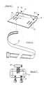
- FIG. 2 shows a rectangular housing jacket plate 1.
- the jacket plate 1 is preferably made of polystyrene, since this material is characterized by elasticity, impact resistance, heat and cold resistance and easy processing.
- a notch 22 can be seen at each of the four corners of the casing jacket plate 1. After the plate 1 has been inserted into the housing frame 5, part of the housing surface area can protrude beyond the housing frame 5.
- Recesses 9 are provided along the longitudinal edge of the plate 1 and serve to receive pins 8 of the side parts 6. After assembly, the side parts 6 lie flat on the inside of the housing frame 5 and on the plate 1 and immovably. The pins 8 are snapped into the recesses 9.
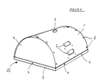
- the cutouts 2 are light entry openings through which a main light source 26, for example an amateur flash unit, can emit its light into the interior of the light pan 21.
- a main light source 26 for example an amateur flash unit
- bores 27 there are bores 27. These bores are used to screw positioning elements 11, which are used to fasten a main light source 26, to the housing jacket 1.
- Figure 3 shows one of the two side parts 6. Both side parts are the same in size and shape and are preferably also made of polystyrene. In the middle of the straight base side of the side part 6, a bore 31 is provided through which a screw 24 can be inserted again. The screw 24 then extends further through an associated bore 4 in the housing frame 5 and can be secured on the opposite side with a knurled nut 25 in the fully assembled light pan. On the semicircular rounding of the side part 6 are the pins 8, which can be inserted into the slots 9 of the jacket plate 1.
- the housing frame 5 is shown in Figure 4.
- angle profiles are used which consist of aluminum in order to achieve a low weight.
- the housing frame has an essentially square or rectangular shape.
- the holes 4 for attaching the housing shell 1 and the side parts 6 can be seen again.
- support elements 32 preferably made of Velcro, are indicated, which are used to attach effect films 15.
- the support elements 32 can of course be attached to the frame 4 at any point and in any length.
- FIG. 5 shows a positioning element 11 for a main light source 26.
- the element 11 is designed as an angled rectangular surface and is provided with bores 13 on the smaller side surface. Through the bores 13, the element 11 can be fastened in the bores 27 of the casing 1 with the aid of screws 33 and wing nuts 34.
- the larger area of the element 11 has various openings and punchings 12.
- the openings 12, which can also be provided at other locations, serve to receive a retaining strap 35, preferably a Velcro strap.
- a suitable selection of openings 12 allows an amateur flash unit of any size to serve as the main light 26 to be easily attached.
- Figure 6 shows a tether 35.
- FIG. 7 shows one of the two fastening elements 17 for connecting the light pan to a stand tube 26.
- a pipe sleeve is used as the fastening element 17.
- the sleeve is provided on its underside with two threaded bores 36 which, in connection with two screws 37 and correspondingly selected bores 28 in the housing jacket 1, serve to fasten the element 17 to the light pan 21.
- On the top of the sleeve 17 is a threaded bore 38 arranged, into which a knurled screw 39 can be screwed. With the help of the knurled screw 39, the fastening element 17 can then be fixed on the tripod boom 26 and thus the light pan 21 can be attached to the tripod.
- FIG. 8 shows a rectangular cover plate 14, likewise preferably made of polystyrene, which is used to cover openings 2 if they are not to be equipped with a main light 26.
- a retaining spring 41 is attached in the middle of the longitudinal edges of the cover plate 14. The retaining springs 41 hold the cover plate 14 on the housing jacket plate 1; the cover plates 14 can also be removed just as easily and quickly.
- FIG. 9 as in FIG. 12, some examples of foils for achieving diffuse and / or effect light are shown.
- the films can be made of clear, matt, colorless or colored film material.
- the foils are so large that they fit onto the light exit opening 42 of the light pan 21. At their corners they are provided with mounting elements 32 of the type already mentioned.
- the support elements 32 can of course extend over the entire edges of the films 15.
- FIG. 10 shows an exemplary embodiment for the arrangement of a modeling light 18, 19.
- a bulb holder 18, a spacer 43, a heat protection plate 16 and a threaded part 44 are screwed into the opening 3 of the housing jacket plate 1.
- FIG 11 is a cross section through the mounted light pan.
- the same components are again provided with the same reference symbols. Their meaning is evident from the description of the preceding drawing figures.
- FIG. 12 shows in perspective how a light pan 21 is suspended from a gallows 26 of a stand 45. This figure also clearly shows how two amateur flash units 26 are arranged on positioning elements 11 with the aid of Velcro strips 35. For advanced amateurs, the possibility can be provided to provide additional recesses 46 for main lights 26 in order to achieve a particularly high light intensity or special lighting effects.
- FIG. 13 exemplary embodiments for diffuser and effect films 15 are shown.
- the film according to FIG. 13a produces a centered spot light.
- the film of Figure 13b results in a soft spot light, the film 13c a light course from dark to bright, the film after 13d a softer light course from dark to light.
- the effect film according to FIG. 13e is an example of a translucent color film of any color.
- the film according to FIG. 13f can result in a color gradient from light to dark in certain colors by means of a corresponding color print.
- a roller blind 48 preferably made of impermeable fabric, is shown in FIG. 15 as an additional device. With the help of the roller blind 48, the area of the light exit opening 42 can be continuously reduced.
Landscapes
- Physics & Mathematics (AREA)
- General Physics & Mathematics (AREA)
- Non-Portable Lighting Devices Or Systems Thereof (AREA)
- Light Sources And Details Of Projection-Printing Devices (AREA)
- Ink Jet (AREA)
- Peptides Or Proteins (AREA)
- Light Guides In General And Applications Therefor (AREA)
Priority Applications (1)
| Application Number | Priority Date | Filing Date | Title |
|---|---|---|---|
| AT88105344T ATE59488T1 (de) | 1987-04-06 | 1988-04-02 | Anordnung zum richten von licht, insbesondere fuer fotografische zwecke. |
Applications Claiming Priority (2)
| Application Number | Priority Date | Filing Date | Title |
|---|---|---|---|
| DE3711568A DE3711568A1 (de) | 1987-04-06 | 1987-04-06 | Anordnung zum richten von licht |
| DE3711568 | 1987-04-06 |
Publications (2)
| Publication Number | Publication Date |
|---|---|
| EP0286040A1 true EP0286040A1 (fr) | 1988-10-12 |
| EP0286040B1 EP0286040B1 (fr) | 1990-12-27 |
Family
ID=6324967
Family Applications (1)
| Application Number | Title | Priority Date | Filing Date |
|---|---|---|---|
| EP88105344A Expired - Lifetime EP0286040B1 (fr) | 1987-04-06 | 1988-04-02 | Dispositif pour diriger la lumière, spécialement pour des buts photographiques |
Country Status (3)
| Country | Link |
|---|---|
| EP (1) | EP0286040B1 (fr) |
| AT (1) | ATE59488T1 (fr) |
| DE (2) | DE3711568A1 (fr) |
Cited By (1)
| Publication number | Priority date | Publication date | Assignee | Title |
|---|---|---|---|---|
| EP0961161A3 (fr) * | 1998-05-25 | 2000-02-09 | Ross M. Horowitz | Système modulaire pour poser et éclairer des objets en photographie |
Families Citing this family (8)
| Publication number | Priority date | Publication date | Assignee | Title |
|---|---|---|---|---|
| DE9006883U1 (de) * | 1990-06-19 | 1990-08-23 | Siemens AG, 1000 Berlin und 8000 München | Reflektoranordnung |
| US5595440A (en) * | 1992-01-14 | 1997-01-21 | Musco Corporation | Means and method for highly controllable lighting of areas or objects |
| US5402327A (en) * | 1992-01-14 | 1995-03-28 | Musco Corporation | Means and method for highly controllable lighting |
| US5647661A (en) * | 1992-01-14 | 1997-07-15 | Musco Corporation | High efficiency, highly controllable lighting apparatus and method |
| US5337221A (en) * | 1992-01-14 | 1994-08-09 | Musco Corporation | Means and method for highly controllable lighting |
| US5519590A (en) * | 1992-01-14 | 1996-05-21 | Musco Corporation | Means and method for highly controllable lighting |
| US6833675B2 (en) | 1998-05-12 | 2004-12-21 | Musco Corporation | Method and apparatus of blocking ultraviolet radiation from arc tubes |
| DE102011119042B4 (de) * | 2011-11-22 | 2015-10-29 | Jürgen Nölle | Leuchte mit Reflektor oder Diffusorschirm |
Citations (5)
| Publication number | Priority date | Publication date | Assignee | Title |
|---|---|---|---|---|
| DE7405896U (de) * | 1974-05-30 | Pfeiffer M | Lichtwanne für Studio-Blitz-Systeme | |
| DE2542049A1 (de) * | 1974-09-26 | 1976-04-15 | Tolec Sarl | Beleuchtungsvorrichtung fuer fotografische oder kinematografische aufnahmen |
| DE2729182A1 (de) * | 1976-08-26 | 1978-03-02 | Raymond George Larson | Lichtdiffusions- und richtvorrichtung |
| GB2100399A (en) * | 1981-06-12 | 1982-12-22 | Cartwright Studios Ltd | Photographer's light |
| EP0077986A1 (fr) * | 1981-10-23 | 1983-05-04 | Tekno AG | Panneau modulaire en matière plastique diffuseur ou réflecteur de lumière pour la photographie, le cinéma, la télévision et l'éclairage de locaux, et dispositif obtenu par l'assemblage de plusieurs de ces panneaux |
-
1987
- 1987-04-06 DE DE3711568A patent/DE3711568A1/de not_active Withdrawn
-
1988
- 1988-04-02 EP EP88105344A patent/EP0286040B1/fr not_active Expired - Lifetime
- 1988-04-02 AT AT88105344T patent/ATE59488T1/de not_active IP Right Cessation
- 1988-04-02 DE DE8888105344T patent/DE3861405D1/de not_active Expired - Lifetime
Patent Citations (5)
| Publication number | Priority date | Publication date | Assignee | Title |
|---|---|---|---|---|
| DE7405896U (de) * | 1974-05-30 | Pfeiffer M | Lichtwanne für Studio-Blitz-Systeme | |
| DE2542049A1 (de) * | 1974-09-26 | 1976-04-15 | Tolec Sarl | Beleuchtungsvorrichtung fuer fotografische oder kinematografische aufnahmen |
| DE2729182A1 (de) * | 1976-08-26 | 1978-03-02 | Raymond George Larson | Lichtdiffusions- und richtvorrichtung |
| GB2100399A (en) * | 1981-06-12 | 1982-12-22 | Cartwright Studios Ltd | Photographer's light |
| EP0077986A1 (fr) * | 1981-10-23 | 1983-05-04 | Tekno AG | Panneau modulaire en matière plastique diffuseur ou réflecteur de lumière pour la photographie, le cinéma, la télévision et l'éclairage de locaux, et dispositif obtenu par l'assemblage de plusieurs de ces panneaux |
Cited By (1)
| Publication number | Priority date | Publication date | Assignee | Title |
|---|---|---|---|---|
| EP0961161A3 (fr) * | 1998-05-25 | 2000-02-09 | Ross M. Horowitz | Système modulaire pour poser et éclairer des objets en photographie |
Also Published As
| Publication number | Publication date |
|---|---|
| ATE59488T1 (de) | 1991-01-15 |
| EP0286040B1 (fr) | 1990-12-27 |
| DE3861405D1 (de) | 1991-02-07 |
| DE3711568A1 (de) | 1988-10-27 |
Similar Documents
| Publication | Publication Date | Title |
|---|---|---|
| DE2740487C3 (de) | Elektronisches Blitzgerät | |
| DE102016123775B4 (de) | Fotografie-LED-Scheinwerfer mit umschaltbarem Direktbeleuchtungsmodus und Weichlichtmodus | |
| DE69403803T2 (de) | Faltbarer Reflektor für photographische Blitzgeräte | |
| DE8702694U1 (de) | Reflektor für fotografische Lichtquellen | |
| DE3809333C2 (fr) | ||
| DE2212502C3 (de) | Überkopfprojektor | |
| EP0286040B1 (fr) | Dispositif pour diriger la lumière, spécialement pour des buts photographiques | |
| DE8516618U1 (de) | Modularer Beleuchtungsprojektor | |
| DE202017107306U1 (de) | Dynamisches Projektionslicht | |
| DE2556034C3 (de) | Integralfototräger zur räumlichen Reproduktion nüt standortverschiedenen Betrachteransichten sowie Belichtungskamera und Reproduziervorrichtung für den Integralfototräger | |
| DE19645023A1 (de) | Lampenvorrichtung eines Flüssigkristall-Projektionsgerätes | |
| DE2542049A1 (de) | Beleuchtungsvorrichtung fuer fotografische oder kinematografische aufnahmen | |
| DE2449708A1 (de) | Roentgendiagnostikeinrichtung mit einem belichtungsautomaten | |
| DE2854615A1 (de) | Vorrichtung zur durchfuehrung von blitzlichtaufnahmen im nahbereich | |
| DE2747916C3 (de) | Schreibprojektor | |
| DE2523643A1 (de) | Reflektor | |
| DE2729378C3 (de) | Vorbelichtungseinrichtung in einer Reproduktionskamera für Rasteraufnahmen | |
| DE3242409A1 (de) | Lichtreklameeinrichtung mit einem lichtdurchlaessigen spiegel | |
| DE1114042B (de) | Projektor mit geknicktem Strahlengang | |
| DE3233257C2 (fr) | ||
| DE1964129C3 (de) | Automatisches Farbauszugsgerät | |
| DE1297460B (de) | Kameravorsatz fuer Nahbildaufnahmen | |
| DE2715963C3 (de) | Beleuchtungsanordnung für photographische Zwecke | |
| DE7021913U (de) | Fotografisches kopiergeraet | |
| DE2904581A1 (de) | Beleuchtungsgeraet fuer fotografische aufnahmezwecke |
Legal Events
| Date | Code | Title | Description |
|---|---|---|---|
| PUAI | Public reference made under article 153(3) epc to a published international application that has entered the european phase |
Free format text: ORIGINAL CODE: 0009012 |
|
| AK | Designated contracting states |
Kind code of ref document: A1 Designated state(s): AT CH DE LI |
|
| 17P | Request for examination filed |
Effective date: 19890308 |
|
| 17Q | First examination report despatched |
Effective date: 19900404 |
|
| GRAA | (expected) grant |
Free format text: ORIGINAL CODE: 0009210 |
|
| AK | Designated contracting states |
Kind code of ref document: B1 Designated state(s): AT CH DE LI |
|
| REF | Corresponds to: |
Ref document number: 59488 Country of ref document: AT Date of ref document: 19910115 Kind code of ref document: T |
|
| REF | Corresponds to: |
Ref document number: 3861405 Country of ref document: DE Date of ref document: 19910207 |
|
| PLBE | No opposition filed within time limit |
Free format text: ORIGINAL CODE: 0009261 |
|
| STAA | Information on the status of an ep patent application or granted ep patent |
Free format text: STATUS: NO OPPOSITION FILED WITHIN TIME LIMIT |
|
| 26N | No opposition filed | ||
| PGFP | Annual fee paid to national office [announced via postgrant information from national office to epo] |
Ref country code: AT Payment date: 19930408 Year of fee payment: 6 |
|
| PGFP | Annual fee paid to national office [announced via postgrant information from national office to epo] |
Ref country code: CH Payment date: 19930419 Year of fee payment: 6 |
|
| PG25 | Lapsed in a contracting state [announced via postgrant information from national office to epo] |
Ref country code: AT Effective date: 19940402 |
|
| PGFP | Annual fee paid to national office [announced via postgrant information from national office to epo] |
Ref country code: DE Payment date: 19940426 Year of fee payment: 7 |
|
| PG25 | Lapsed in a contracting state [announced via postgrant information from national office to epo] |
Ref country code: LI Effective date: 19940430 Ref country code: CH Effective date: 19940430 |
|
| REG | Reference to a national code |
Ref country code: CH Ref legal event code: PL |
|
| PG25 | Lapsed in a contracting state [announced via postgrant information from national office to epo] |
Ref country code: DE Effective date: 19960103 |