EP0286093B1 - Procédé d'obtention électrolytique de métal utilisant une unité d'électrodes formée d'un assemblage de plaques d'anode et de cathode et cadre pour la construction d'une telle unité d'électrodes - Google Patents
Procédé d'obtention électrolytique de métal utilisant une unité d'électrodes formée d'un assemblage de plaques d'anode et de cathode et cadre pour la construction d'une telle unité d'électrodes Download PDFInfo
- Publication number
- EP0286093B1 EP0286093B1 EP88105556A EP88105556A EP0286093B1 EP 0286093 B1 EP0286093 B1 EP 0286093B1 EP 88105556 A EP88105556 A EP 88105556A EP 88105556 A EP88105556 A EP 88105556A EP 0286093 B1 EP0286093 B1 EP 0286093B1
- Authority
- EP
- European Patent Office
- Prior art keywords
- plates
- frame body
- anode
- cathode
- electrode
- Prior art date
- Legal status (The legal status is an assumption and is not a legal conclusion. Google has not performed a legal analysis and makes no representation as to the accuracy of the status listed.)
- Expired - Lifetime
Links
- 229910052751 metal Inorganic materials 0.000 title claims description 35
- 239000002184 metal Substances 0.000 title claims description 35
- 238000005363 electrowinning Methods 0.000 title claims description 17
- 238000000034 method Methods 0.000 title description 12
- 239000012777 electrically insulating material Substances 0.000 claims description 2
- 238000011282 treatment Methods 0.000 description 24
- 238000012546 transfer Methods 0.000 description 23
- 238000005868 electrolysis reaction Methods 0.000 description 16
- 238000000151 deposition Methods 0.000 description 8
- 230000008021 deposition Effects 0.000 description 8
- 230000007246 mechanism Effects 0.000 description 7
- 238000005498 polishing Methods 0.000 description 6
- 125000006850 spacer group Chemical group 0.000 description 6
- 239000007921 spray Substances 0.000 description 6
- 238000005406 washing Methods 0.000 description 6
- 206010039509 Scab Diseases 0.000 description 5
- HCHKCACWOHOZIP-UHFFFAOYSA-N Zinc Chemical compound [Zn] HCHKCACWOHOZIP-UHFFFAOYSA-N 0.000 description 5
- 238000007790 scraping Methods 0.000 description 5
- 229910052725 zinc Inorganic materials 0.000 description 5
- 239000011701 zinc Substances 0.000 description 5
- 238000007796 conventional method Methods 0.000 description 3
- 239000011810 insulating material Substances 0.000 description 3
- 230000009467 reduction Effects 0.000 description 3
- MYMOFIZGZYHOMD-UHFFFAOYSA-N Dioxygen Chemical compound O=O MYMOFIZGZYHOMD-UHFFFAOYSA-N 0.000 description 2
- 229910001882 dioxygen Inorganic materials 0.000 description 2
- 239000003792 electrolyte Substances 0.000 description 2
- 238000003780 insertion Methods 0.000 description 2
- 230000037431 insertion Effects 0.000 description 2
- 239000003595 mist Substances 0.000 description 2
- 230000008569 process Effects 0.000 description 2
- 238000007670 refining Methods 0.000 description 2
- XLYOFNOQVPJJNP-UHFFFAOYSA-N water Substances O XLYOFNOQVPJJNP-UHFFFAOYSA-N 0.000 description 2
- RYGMFSIKBFXOCR-UHFFFAOYSA-N Copper Chemical compound [Cu] RYGMFSIKBFXOCR-UHFFFAOYSA-N 0.000 description 1
- 229910000978 Pb alloy Inorganic materials 0.000 description 1
- 238000005452 bending Methods 0.000 description 1
- 210000000078 claw Anatomy 0.000 description 1
- 229910052802 copper Inorganic materials 0.000 description 1
- 239000010949 copper Substances 0.000 description 1
- 238000013461 design Methods 0.000 description 1
- 210000005069 ears Anatomy 0.000 description 1
- 238000007654 immersion Methods 0.000 description 1
- 239000012212 insulator Substances 0.000 description 1
- 239000000463 material Substances 0.000 description 1
- 150000002739 metals Chemical class 0.000 description 1
- 238000007494 plate polishing Methods 0.000 description 1
- 230000008439 repair process Effects 0.000 description 1
- 230000000717 retained effect Effects 0.000 description 1
- 239000010802 sludge Substances 0.000 description 1
- 238000003466 welding Methods 0.000 description 1
Images




Classifications
-
- C—CHEMISTRY; METALLURGY
- C25—ELECTROLYTIC OR ELECTROPHORETIC PROCESSES; APPARATUS THEREFOR
- C25C—PROCESSES FOR THE ELECTROLYTIC PRODUCTION, RECOVERY OR REFINING OF METALS; APPARATUS THEREFOR
- C25C1/00—Electrolytic production, recovery or refining of metals by electrolysis of solutions
- C25C1/16—Electrolytic production, recovery or refining of metals by electrolysis of solutions of zinc, cadmium or mercury
-
- C—CHEMISTRY; METALLURGY
- C25—ELECTROLYTIC OR ELECTROPHORETIC PROCESSES; APPARATUS THEREFOR
- C25C—PROCESSES FOR THE ELECTROLYTIC PRODUCTION, RECOVERY OR REFINING OF METALS; APPARATUS THEREFOR
- C25C7/00—Constructional parts, or assemblies thereof, of cells; Servicing or operating of cells
Definitions
- This invention relates to electrowinning and electrolytic refining of zinc, copper, and other metals which is efficient in electrolysis and enables electrode-handling operations such as immersing and lifting into and from an electrolytic cell and various treatments to be carried out easily.
- electrowinning is hereinafter used as including “electrolytic refining”.
- cathode plates and anode plates are alternately arranged at equal intervals. Often, cathode plates and anode plates are hung in an electrolytic cell separately plate by plate. The reason is that the cathodes are used as mother plates on which the electrolyzed metal is deposited and recovered while the anode plates are merely used as electrodes, and it suffices if only the cathode plates are taken out of the cell in order to recover the deposited metal.
- the cathode plates and anode plates are separately hung plate by plate in an electrolytic cell as has been done, the electrode plates are liable to swing and to contact each other, causing electrical short circuiting. Therefore, the cathode and the anode are spaced apart at a considerably wide distance in comparison with the thickness of the metal to be deposited on the cathode surface. This makes the electrolytic cell larger and increases electric resistance, which invites inefficiency in electrolysis and increase in power consumption.
- the anode plates are made of rather soft lead or lead alloy and, therefore, easily bend, which also may cause mutual contacting of electrodes at the edge portions although the central portions are separated. Also there is a danger that anode plates may be bent when they are inserted into the spaces between the insulating rods and cause contacting with the adjacent plate.
- the cathode plates are taken out from the electrolytic cell for stripping of deposited zinc every time one period operation of electrolysis is finished, and again they are immersed in the cell after they have undergone the stripping and other treatments.
- the anode plates are taken out of the cell after every several cycles of electrolysis for servicing such as removal of crusts formed on the surface thereof.
- the crust formed on the anode surface increases the electrolysis resistance and deteriorates electrolysis efficiency. Therefore, it is desirable to remove the crust as frequently as possible.
- DE-A-28 53 672 shows a frame body formed by four distinct, elongated beams.
- the beams may be handled separately and have to be connected at their respective ends to form the complete frame body.
- the vertical beams and the bottom beam are generally U-shaped and include inwardly projecting protrusions which act as fixing members to receive the edges of an electrode plate.
- edge baffles which extend outwardly from either anode side edge portion to provide a spaced apart relationship between the cathodes and anodes.
- the edge baffles also prevent deposition of metal at the edges of the cathodes because the cathodes extend beyond the width defined by the baffles.
- the cathodes are additionally held in slots of an alignment device.
- One object of the present invention is to provide a frame body for electrowinning a metal comprising using at least one electrode unit which comprises a plurality of anode plates and cathode plates alternately, insulatedly and separably assembled.
- Another object of the present invention is to provide a frame body for electrowinning a metal as described above, wherein it is possible to carry out immersion and lifting of the electrodes into and from an electrolytic cell and various treatments of the electrodes unit by unit.
- Still another object of the present invention is to provide a frame body for electrowinning a metal as described above, a series of procedures of lifting of the electrode plates from the electrolytic cell, electrode treatments and immersing the electrodes again in the electrolytic cell may be continuously carried out as the cathode plates and anode plates are simultaneously suspended by transfer means.
- Still another object of the present invention is to provide a frame body for electrowinning a metal as described above, wherein the electrode unit is disassembled after the unit is lifted from the electrolytic cell, and during and after transfer, the separated anode plates with frame bodies and cathode plates are simultaneously suspended and subjected to various treatments, whereafter the electrode plates are assembled again and immersed in the electrolytic cell as a unit.
- Still another object of the present invention is to provide a frame body for electrowinning a metal as described above, wherein the frame bodies are removed from the anode plates after the electrode units are lifted from the electrolytic cell and they are fixed to the anodes before the electrode plates are assembled again.
- a frame body made of an electrically insulating material for forming an electrode unit, said frame body comprising two frames which constitute a frame body and hold an electrode plate, fixing members for holding an electrode plate, engaging member which engages with another frame body, and short-circuiting preventing members which prevent contacting of the crossbars of the electrodes.
- the frame body is rectangular so as to encompass the outer edges of an anode plate, a plurality of the fixing members each of which comprises a pair of clamp means are provided sandwitched between the two frames, the engaging member is a pair of strips projected from the two side edges of one of the two frames extending toward an adjacent frame body to receive a cathode plate therebetween.
- clearances are provided at part the bottom periphery and side peripheries of the frames.
- the term electrode unit means an assembly of a plurality of anode plates and cathode plates which are alternately, insulatedly and separably arranged, the means for assembling not being concerned.
- the simplest form of the electrode unit is an assembly of a plurality of alternately arranged and mutually insulated anode plates and cathode plates with small spaces therebetween to be immersed in an electrolytic cell.
- various measures can be resorted to. That is, anode plates and cathode plates can be assembled by holding them alternately by means of a pair of connecting members with spacedly arranged insulating spacers, whereby a pair of connector members simultaneously functions as insulators and/or spacers.
- Frames of various shapes and structures can be used if they can hold the anode and cathode plates alternately with spaces therebetween.
- an insulating frame can be individually fixed to an anode plate which can engage with an adjacent frame by means of engaging members provided thereon, or a three-dimensional frame which can contain a plurality of anode and cathode plates which are alternately arranged with spaces therebetween, etc. can he used.
- a specific example of such a frame is a frame body which comprises a pair of rectangular frames which can encompass an electrode, and are provided with anode-fixing members, engaging member which engages with another adjacent frame body, short-circuiting preventing members which prevent contacting of the cross bars.
- the anode-fixing member is a clip means comprising a pair of nail-like members which hold peripheries of an anode, and a plurality of them are attached to the vertical beams of the frames sandwitched therebetween projecting inward at the symmetrical positions.
- the anode-fixing members are also provided in the bottom beams of the frame bodies.
- the engaging member is a pair of strips each projected from one edge of one of the two frames extending toward an adjacent frame body to receive a cathode plate therebetween.
- Frame bodies respectively hold an anode plate and are alternately arranged with cathode plates and connected to form an electrode unit, wherein the frame bodies work as spacers.
- the space between an anode and a cathode can be designed far smaller than the convention design.
- the space between an anode and a cathode can be made smaller by reducing the thickness of the spacer or the frame, the space cannot be made excessively small. Because, if the inter-electrode space is excessively small, the thickness of the metal to be deposited is restricted. Thin deposited metal is not easy to strip off. Therefore, the space is suitably selected by considering species of metal to be doposited, conditions of electrolysis, etc.
- An electrode unit is immersed in an electrolytic cell as is for electrolysis, and it is lifted after the electrolysis.
- the unit which has been lifted is subjected to various treatments before it is immersed in an electrolytic cell again.
- the treatments which the electrodes undergoes are different in accordance with the structure of the electrode unit. Whatever treatments electrodes undergo, if the electrodes are assembled into a unit and the unit is used in the electrolysis, such processes belong to the present invention.
- the cathode plates and anode plates are subjected to various treatments including stripping of the deposited metal without being separated into the anode group and the cathode group. Therefore, the anodes and cathodes are again simultaneously returned to the electrolysis step.
- stripping of the deposited metal and servicing of the electrode plate are carried out unit by unit.
- the modes of the electrode unit include various embodiments.
- the spacer-clamp means or three-dimensional frame are removed when the electrode plates are transferred to various treatment stations as suspended from a transfer means. Thereafter the electrodes are assembled again by the clamp-spacers or the frame for reimmersion into the electrolytic cell.
- An electrode unit can be formed by means of frame means of an insulating material respectively fixed to an electrode, which are connected to each adjacent frame body, the connected frame bodies are disconnected after the unit is lifted from the electrolytic cell, the electrode plates are subjected to various treatments as suspended from a transfer means without removing frame bodies. After the treatments have been finished, the electrode are reassembled to a unit, and immersed in an electrolytic cell. In some cases, the frame bodies are removed from anode plates if required.
- the anode plates and the cathode plates are subjected to various electrode treatments including stripping of the deposited metal, washing and servicing of the electrodes, etc. as they are suspended from a transfer means such as an overhead crane.
- the inter-electrode space can be made remarkably small.
- the distance between the surface of the adjacent anode plate and cathode plate can be as close as about 14 mm in contrast, with about 30 - 35 mm in conventional processes. That it, the space can be reduced to about 1/2. This means reduction in electrolysis resistance, i.e. reduction in power consumption. Further, the electrolytic cell can be made more compact, which means reduction of the operation space.
- an electrode unit By the employment of an electrode unit, handling of the electrodes is simplified and operation efficiency is improved. Stripping of deposited metal, washing and other treatments are carried out unit by unit and it is suitable to automate a series of operations from electrolysis to treatments of electrodes.
- the anode plates and the cathode plates on which the object metal has been deposited are simultaneously lifted as a unit as the electric current retained in contrast with the conventional method in which the anode plates and cathode plates are lifted separately.
- the electrodes can be continuously treated as suspended from a transfer means. Therefore, the operation can be carried out more rapidly than conventional methods.
- a plurality of electrode plates can be simultaneously treated as suspended from a transfer means, which means higher operation efficiency is achieved.
- Fig. 1A is a partially cut-off perspective view of a frame body used in the present invention.
- Fig. 1B is a schematic horizontal cross-sectional view of the frame body shown in Fig. 2 along the line A - A.
- Fig. 2 is an elevational view of a frame body, which holds an anode plate.
- Fig. 3 is a partially cross sectional elevational view of the frame body as shown in Fig. 2 along the line X - X. In this drawing, cathode plates 4 are also shown.
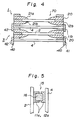
- Fig. 4 is a schematic horizontal cross-sectional view of electrode plates assembled by two of the frame bodies along the line B - B in Fig. 2.
- Fig. 5 is a schematic partial cross-sectional view of the upper beam of a frame of the frame body.
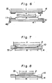
- Figs. 6 - 8 are schematic horizontal view representing the relation of the sizes of the anode and cathode and the state of the deposition of metal.
- Fig. 9 is a plan view showing the layout of the electrolytic cells and various treatment stations.
- Figs. 10A and 10B are schematic perspective views showing an example of the electrode-handling apparatus.
- Figs. 11 and 12 are a schematic elevational view and a schematic side view of an anode-servicing apparatus.
- Figs. 13 and 14 are a schematic elevational view and a schematic side view of a cathode-polishing apparatus.
- a frame body 1 comprises two frames 11, 12 of an insulating material such as a plastic, which hold an anode plate 2, fixing means 20 which fix an anode plate 2 to the frame body, short-circuiting preventing means 30 which prevent contacting of the electrode plates 2, 4 and an engaging member 40 which engages the frame body 1 with an adjacent frame body 3.
- the frame body 1 is rectangular so as to enclose an anode plate 2 and comprises two frames 11 and 12.
- the frames 11 and 12 respectively comprises horizontal beams 11a and 12a and vertical beams 11b and 12b.
- the space between the vertical beams 11b, 12b is preferably partly a little wider than the width of the anode plate 2 so that a clearance 50 (1 - 2 cm) is formed between the frame body 1 and the anode plate 2 through which the electrolyte can flow as shown in Figs. 1A and 2.
- the horizontal beams 11a and 12a are provided with bolt holes 13 and 14 with which an anode can be fixed to the frame body as shown in Figs. 1A and 3. This fixing can also be made by welding, if desired.
- the upper horizontal beams 11a and 12a may be hollow tubes having vent holes or a slit so that they are packed with a filter material which collect the mist generated from the surface of the electrolytic bath as shown in Fig. 5. That is, oxygen gas, etc. which are produced from the surface of the electrolytic bath diffuses out through the vent holes or slit 15. The mist of the electrolyte which is entrained by the oxygen gas, etc. is collected by the filter 16 packed in the beams, which can be periodically replaced.
- the fixing means 20 is a pair of resilient clamps 21a and 21b spacedly secured together at the base and having a clearance 22 (Figs. 1A and 1B).
- the edge of an anode plate 2 is inserted therein and clamped by the resilient force thereof.
- the frames 11 and 12 are preferably designated so that there are some clearances 50 partly shown in Fig. 2. That is, the depth of the clearance 22 is such that the bottom thereof is located at slightly inside of the inner edges of the frames 11 and 12, whereby the clearance 50 is formed around the anode plate 2 secured by the fixing means 20 as shown in Fig. 1B and Fig. 2.
- the short-circuiting-preventing means 30 are strips which are protruded from the ends of the upper beams 11a and 12a in the case of the example illustrated in Fig. 1A. These can be combined in an inverted U shape so that the frame members 11 and 12 can be hung from a cross bar 2a, 4a.
- the engaging member 40 which is a pair of strips 41 and 42 projected from both sides of a frame 11, make one frame body 1 engage with another frame body 3 with a cathode plate 4 held therebetween.
- the engaging member 40 holds an adjacent frame body 3 between it and covers the side edges of the cathode plate 4 held between the two frame bodies 1 and 3. If the side edges of the cathode plates are exposed, the object metal deposits thereon and grows to contact the deposit on the adjacent cathode plate. This makes difficult the stripping of the deposited object metal. That is, as shown in Fig. 4, an electrode unit 70 is assembled by combining a first frame body 1, a second frame body 3, etc. holding an anode plate 2 by the anode fixing means 20 and holding a cathode plate 4 between the frame bodies 1 and 3 by means of the engaging member 40.
- the thus formed electrode unit (denoted as 70) by means of a pair of clamp bars 71 (see Fig. 12A), which extend over the whole thickness of the assembled anodes and cathodes and secure them by means of claws provided at both ends thereon.
- the clamp bars 71 are removed when the electrode unit is lifted from the electrolytic cell and transferred to electrode-treating stations.
- the length of the horizontal frame beams (11a and 12a) is approximately the same as the width l (Fig. 6) of a cathode plate 4, and the side peripheries of a cathode are covered by vertical beams 110 and 12b. Therefore, the width m of the deposition surface of a cathode plate is a little shorter than the width l of the cathode plate 4 (Fig. 6). If the width m of the deposition surface of the cathode plate 4 is shorter than the width n of the anode plate 2, and thus the both periphery of the deposition surface are inside of the side edges of the anode plate 2 as shown in Fig. 7.
- the electric current density in electrolysis is higher at the side peripheries than the central portion, and thus more metal 51 is deposited at the peripheries as ridges, which may grow to contact the anode plate 2 to cause short-circuiting.
- the width m of the deposition surface of the cathode 4 is greater than the width n of the anode plate 2 as shown in Fig. 8, deposition of the metal is thinner at the peripheries, which will make it difficult to insert a scraping knife between the deposited metal 51 and the cathode surface.
- the width m of the deposition surface of the cathode plate 4 is only slightly greater than the width n of the anode plate, and, therefore is free from the difficulty as explained above with respect to Fig. 8.
- electrolytic cells 120a, 120b, 120c, 120d, 120e, 120f, 120g, 120h, 120i an anode plate servicing station 130, a cathode plate washing station 140, a cathode plate polishing station 150, a stripping station 160, etc. are arranged along the travelling course of a transfer means 100.
- a suitable transfer apparatus 100 is illustrated in Figs. 10A and 10B.
- the apparatus comprises a travelling general framework 111, a driving mechanism 112 for the framework 111, a hanger-supporting frame 113 which is mounted on the framework 111 and can be lifted and lowered, a plurality of hangers 114 which are mounted on the hanger-supporting frame 113 and are movable along the beams of the hanger-supporting frame, hanger-driving mechanism 115 which displace the hangers spacing them apart or bringing them together, tilting hook members 110 suspended from the hangers 114 and catch the ears of the electrode plates, and a hook-driving mechanism 117 which operates the hooks to catch or release the electrode plates.
- the framework 111 travels suspended from overhead rails 111a and 111b for instance, or otherwise, travels on rails laid on the plant floor.
- the hangers and the hanger-supporting frame are insulated by insulating members inserted therebetween.
- the hangers 114a and 114b are serially connected by links 118 and there is provided on the hanger-supporting frame chain mechanisms 119a and 119b, one of which moves the hanger in one direction and the other of which moves it in the opposite direction.
- the hangers connected by the links 118 are spaced apart, that is, expanded, or brought together.
- an electrode unit is lifted by the transfer apparatus.
- Clamp bars (if used) and frame bodies which have assembled the electrodes are removed, during the travelling for instance, the hangers are displaced and the inter-electrode space is widened and the electrode plates are transferred to an anode-servicing station.
- the assembled electrodes of which the inter-electrode space is 15 - 30 mm con be separated to 150 - 250 mm.
- anode crusts are removed.
- An example of the anode-servicing apparatus 131 is illustrated in Figs. 11 and 12.
- the illustrated anode servicing apparatus 131 comprises a plurality of spacedly positioned vertical spray pipes 132 having a series of spray nozzle orifices. The distance between the adjacent spray pipes is equal to the distance between an anode plate and the adjacent cathode plate when the linked hangers are most expanded, and the spray nozzle orifices are provided on the side of the pipes facing the anode plates.
- the anode and cathode plates suspended widest apart from the transfer apparatus respectively can pass through the space between the adjacent spray pipes, and the anode plates and the frames are washed with high pressure jets of water from the nozzle orifices.
- This operation can be automatically controlled by means of sensors and related automatic control devices.
- the anode plates are held by their frame bodies and, therefore, the anode plates are satisfactorily protected from deformation which they may otherwise suffer during the servicing operation. That is, the method of this invention eliminates the need to repair electrodes which have been bent by accident.
- the cathode plates can be washed while they pass a cathode servicing station 140, which is constructed in the same manner as the above-described anode servicing station 131.
- the cathodes are preferably washed with hot water.
- servicing of the anode plates and cathode plates can be simultaneously effected by providing nozzle orifices on both sides of spray pipes 132 on the anode servicing apparatus 131.
- the anode plates 2 and cathode plates 4 suspended from the transfer apparatus 110 which have been washed by the anode servicing apparatus 131 and a cathode servicing apparatus are transferred to a stripping station 160.
- the cathode plates which are suspended from the transfer apparatus 100 together with the anode plates under the widest-spaced condition are subjected to a scraper 161.
- the scraper 161 is provided with a plurality of scraping knives 162a, 162b, etc. so that a plurality of cathode plates can be stripped.
- the distance between a cathode plate and another adjacent cathode plate is set to be the same as the distance between the scraping knife 162a and the other scraping knife 162b (Fig. 9) Stripping is effected as the electrode plates 2 and 4 are suspended from the transfer apparatus.
- the clearance 50 between the edge of the anode plate and the edge of the frame beams is not provided at the upper part of the frame 10 as seen in Fig. 2.
- the state as shown in Fig. 7 is partly caused in the upper part of the cathode plate. This makes easy insertion of a scraping knife. That is, a knife edge can easily inserted at the point where the deposited metal layer has a steep (not inclined) edge.
- stripping can be effected while the electrode plates 2 and 4 are suspended from the transfer apparatus.
- stripping can be performed by the conventional scraper means without hindrance from the neighboring anode plate.
- the electrodes 2 and 4 are transferred to a cathode polishing station 150.
- the polishing of the cathodes is also performed while the anode and cathode plates are suspended from the transfer apparatus. In this step, polishing brushes, etc. can be provided without difficulty because the distance between a cathode plate and the adjacent anode plate is 150 - 250 mm as mentioned before.
- FIG. 13 and 14 An example of a cathode polishing device 151 is shown in Figs. 13 and 14.
- the polishing device is a pair of closely positioned rotatable vertical cylindrical brushes 152a and 152b provided at the positions of the cathode plates when they are suspended the most extendedly.
- the cathode plates pass through the pair of rotating brushes as the transfer apparatus 100 travels.
- the direction and rate of rotation of the brushes can be regulatable in accordance with the direction and velocity of the travelling of transfer apparatus 100.
- the bundle of the electrodes are tightened before or during the transfer apparatus travels to an electrolytic cell.
- the pair of clamp bars are fixed to the bundle of the tightened electrodes to form an electrode unit again, and the thus reassembled electrode unit is immersed in an electrolytic cell.
- the number of the electrode assembled into a unit or the number of units handled in a cycle of operation is arbitrary.
- One preferred example is as follows.
- the electrodes to be used in an electrolytic cell are formed into two units. While one unit of the electrodes are used for electrowinning, the other unit of the electrodes can be treated outside of the cell, and the half space of the electrolytic cell where the electrode unit has previously been immersed can be cleaned with electrolytic current maintained while the electrodes of the unit are treated. That is, anode sludge, etc. can be drawn out by suction.
- a series of procedures in the method of the present invention can be automated by means of automatic control mechanisms provided in the respective treating devices and the transfer apparatus.
- These automatic control mechanisms of course comprises sensors, control logic circuits, etc. which are usually used.
Landscapes
- Chemical & Material Sciences (AREA)
- Engineering & Computer Science (AREA)
- Chemical Kinetics & Catalysis (AREA)
- Electrochemistry (AREA)
- Materials Engineering (AREA)
- Metallurgy (AREA)
- Organic Chemistry (AREA)
- Electrolytic Production Of Metals (AREA)
Claims (2)
- Structure de châssis destinée à former une unité d'électrode constituée d'un matériau isolant électriquement notamment pour l'utilisation dans l'extraction électrolytique d'un métal, comprenant des éléments de fixation pour maintenir une plaque d'électrode, la structure de châssis étant caractérisée en ce que- la structure de châssis (1) est constituée de deux châssis rectangulaires (11, 12) de façon à envelopper les bords extérieurs d'une plaque d'anode (2) ;- les éléments de fixation (20) dont chacun comprend une paire de moyens de bridage (21a, 21b) sont pris en sandwich entre les deux châssis (11, 12) ;- il est prévu un élément d'engagement (40) qui coopère avec un autre corps de châssis (1), l'élément d'engagement étant constitué par une paire de bandes (41, 42) faisant sailllie à partir des deux bords latéraux (11b) de l'un (11) des deux châssis (11 ; 12) s'étendant vers une structure de châssis contiguë (1) pour y recevoir une plaque de cathode (4) ; et des éléments (30) empêchant les courts-circuits qui empêchent la mise en contact des barres transversales (2a) des électrodes.
- Structure de châssis selon la revendication 1, caractérisée en ce que des débattements ou jeux (50) sont prévus sur la périphérie inférieure et sur une partie des périphéries latérales de la structure de châssis (1).
Applications Claiming Priority (6)
| Application Number | Priority Date | Filing Date | Title |
|---|---|---|---|
| JP87106/87 | 1987-04-10 | ||
| JP8710687A JPH0713315B2 (ja) | 1987-04-10 | 1987-04-10 | 極板型枠 |
| JP96291/87 | 1987-04-21 | ||
| JP62096291A JPH0768628B2 (ja) | 1987-04-21 | 1987-04-21 | 電解製錬における極板処理方法 |
| JP62166892A JPH0768629B2 (ja) | 1987-07-06 | 1987-07-06 | ユニット化された極板を用いた電解方法 |
| JP166892/87 | 1987-07-06 |
Publications (2)
| Publication Number | Publication Date |
|---|---|
| EP0286093A1 EP0286093A1 (fr) | 1988-10-12 |
| EP0286093B1 true EP0286093B1 (fr) | 1993-06-23 |
Family
ID=27305406
Family Applications (1)
| Application Number | Title | Priority Date | Filing Date |
|---|---|---|---|
| EP88105556A Expired - Lifetime EP0286093B1 (fr) | 1987-04-10 | 1988-04-07 | Procédé d'obtention électrolytique de métal utilisant une unité d'électrodes formée d'un assemblage de plaques d'anode et de cathode et cadre pour la construction d'une telle unité d'électrodes |
Country Status (7)
| Country | Link |
|---|---|
| US (1) | US5002642A (fr) |
| EP (1) | EP0286093B1 (fr) |
| KR (1) | KR940002259B1 (fr) |
| AU (2) | AU595996B2 (fr) |
| CA (1) | CA1329382C (fr) |
| DE (1) | DE3881933T2 (fr) |
| FI (1) | FI87659C (fr) |
Families Citing this family (20)
| Publication number | Priority date | Publication date | Assignee | Title |
|---|---|---|---|---|
| FI79723C (fi) * | 1987-12-17 | 1990-02-12 | Outokumpu Oy | Saett att foerstyva och utraeta startplaotar. |
| AU627287B2 (en) * | 1989-03-17 | 1992-08-20 | Plastic Fabricators (WA) Pty Ltd | Electrolytic cell, electrode and frame therefor |
| ES2069496B1 (es) * | 1993-08-10 | 1995-11-01 | Asturiana De Zinc Sa | Cuba para instalaciones de electrolisis. |
| DE19650228C2 (de) * | 1996-12-04 | 1999-09-02 | Metallgesellschaft Ag | Elektrolysezelle mit bipolaren Elektroden |
| FI108545B (fi) * | 1997-06-18 | 2002-02-15 | Outokumpu Oy | Anodi elektrolyyttiseen puhdistukseen |
| AUPQ213099A0 (en) | 1999-08-10 | 1999-09-02 | Technological Resources Pty Limited | Pressure control |
| US6231730B1 (en) | 1999-12-07 | 2001-05-15 | Epvirotech Pumpsystems, Inc. | Cathode frame |
| US6483036B1 (en) * | 2001-01-16 | 2002-11-19 | Quadna, Inc. | Arrangement for spacing electrowinning electrodes |
| FI113280B (fi) * | 2002-04-03 | 2004-03-31 | Outokumpu Oy | Elektrolyysissä käytettävä siirto- ja eristyslaite |
| FI125637B (en) * | 2011-11-28 | 2015-12-31 | Outotec Oyj | Frame and electrolysis system |
| US20190078223A1 (en) * | 2013-07-22 | 2019-03-14 | Percy Danilo Yanez Castaneda | Anode-stiffening device and stiffening system that uses said device |
| DE102014013410A1 (de) * | 2014-09-10 | 2016-03-10 | Li-Tec Battery Gmbh | Energiespeichereinrichtung und Verfahren zu deren Herstellung |
| FI127029B (fi) * | 2015-12-22 | 2017-10-13 | Outotec Finland Oy | Sähkökemiallinen reaktori, vedenkäsittelylaitteisto ja -järjestelmä sekä menetelmä vedenkäsittelylaitteiston ohjaamiseksi |
| CN107699924B (zh) * | 2017-11-13 | 2024-04-02 | 温岭市忠盛金属材料有限公司 | 一种碱性电解金属锌粉中的阴极板剥离金属锌粉设备 |
| CL2019002623A1 (es) * | 2018-09-13 | 2020-03-06 | Percy Danilo Yanez Castaneda | Dispositivo y sistema para eliminar cubre bordes de electrodos |
| CN110142595A (zh) * | 2019-05-16 | 2019-08-20 | 中国能源建设集团山西电力建设第三有限公司 | 电除尘器阴阳极板组合及起吊集成平台及组合起吊方法 |
| CN112340815B (zh) * | 2019-08-06 | 2023-08-25 | 无锡小天鹅电器有限公司 | 电解组件、电解装置及衣物处理设备 |
| CN113526619B (zh) | 2019-08-06 | 2023-06-20 | 无锡小天鹅电器有限公司 | 电解组件及衣物处理设备 |
| CN110592655B (zh) * | 2019-09-03 | 2024-04-23 | 昆山东威科技股份有限公司 | 极板的夹持机构、极板间距的调整结构及电解蚀刻设备 |
| MX2022004358A (es) * | 2019-10-10 | 2022-07-27 | Percy Danilo Yanez Castaneda | Dispositivo optimizador de electrodeposicion de metales y sistema. |
Family Cites Families (9)
| Publication number | Priority date | Publication date | Assignee | Title |
|---|---|---|---|---|
| US1715411A (en) * | 1927-08-22 | 1929-06-04 | Kohler Co | Electroplating rack |
| GB1045816A (en) * | 1964-11-05 | 1966-10-19 | David J Evans Res Ltd | Improvements in or relating to electrodes for electrolytic cells |
| US3579431A (en) * | 1968-02-23 | 1971-05-18 | Bunker Hill Co | Cell for electrolytic deposition of metals |
| US3761385A (en) * | 1971-06-30 | 1973-09-25 | Hooker Chemical Corp | Electrode structure |
| US4033839A (en) * | 1975-02-26 | 1977-07-05 | Kennecott Copper Corporation | Method for series electrowinning and electrorefining of metals |
| JPS5296904A (en) * | 1976-02-10 | 1977-08-15 | Mitsui Mining & Smelting Co | Apparatus for automatic replacement of plate electrode in electrolysis of metals |
| US4113586A (en) * | 1977-10-25 | 1978-09-12 | Kennecott Copper Corporation | Method and apparatus for the electrolytic recovery of metal employing electrolyte convection |
| DE2853672A1 (de) * | 1978-12-13 | 1980-06-26 | Joh Jac Vowinckel Gmbh | Elektrodenrahmen fuer die elektrolytische gewinnung oder raffination von metallen |
| US4568434A (en) * | 1983-03-07 | 1986-02-04 | The Dow Chemical Company | Unitary central cell element for filter press electrolysis cell structure employing a zero gap configuration and process utilizing said cell |
-
1988
- 1988-04-07 DE DE88105556T patent/DE3881933T2/de not_active Expired - Fee Related
- 1988-04-07 EP EP88105556A patent/EP0286093B1/fr not_active Expired - Lifetime
- 1988-04-08 AU AU14430/88A patent/AU595996B2/en not_active Ceased
- 1988-04-08 US US07/179,543 patent/US5002642A/en not_active Expired - Fee Related
- 1988-04-08 CA CA000563645A patent/CA1329382C/fr not_active Expired - Fee Related
- 1988-04-09 KR KR1019880004054A patent/KR940002259B1/ko not_active Expired - Fee Related
- 1988-04-11 FI FI881677A patent/FI87659C/fi not_active IP Right Cessation
-
1990
- 1990-02-02 AU AU49039/90A patent/AU625401B2/en not_active Ceased
Also Published As
| Publication number | Publication date |
|---|---|
| DE3881933D1 (de) | 1993-07-29 |
| KR880012797A (ko) | 1988-11-29 |
| DE3881933T2 (de) | 1994-02-10 |
| KR940002259B1 (ko) | 1994-03-19 |
| AU4903990A (en) | 1990-05-24 |
| AU1443088A (en) | 1988-11-03 |
| AU595996B2 (en) | 1990-04-12 |
| AU625401B2 (en) | 1992-07-09 |
| FI881677A7 (fi) | 1988-10-11 |
| EP0286093A1 (fr) | 1988-10-12 |
| FI87659C (fi) | 1993-02-10 |
| FI881677A0 (fi) | 1988-04-11 |
| FI87659B (fi) | 1992-10-30 |
| CA1329382C (fr) | 1994-05-10 |
| US5002642A (en) | 1991-03-26 |
Similar Documents
| Publication | Publication Date | Title |
|---|---|---|
| EP0286093B1 (fr) | Procédé d'obtention électrolytique de métal utilisant une unité d'électrodes formée d'un assemblage de plaques d'anode et de cathode et cadre pour la construction d'une telle unité d'électrodes | |
| AU612639B2 (en) | Apparatus for hanging and handling plate members | |
| KR890005305A (ko) | 금속을 전기 도금하는 공정 | |
| US4840710A (en) | Method of stripping electrolytically deposited copper from a cathode | |
| JP4712973B2 (ja) | 陰極から金属析出物を分離する装置 | |
| CA1044648A (fr) | Support d'electrodeposition | |
| CA1044647A (fr) | Support d'electrodeposition | |
| EP0873434B1 (fr) | Procede de production d'une plaque mere pour l'affinage et la recuperation electrolytique et plaque mere produite selon ledit procede | |
| RU2116387C1 (ru) | Способ и устройство для очистки электродов электролитических ванн | |
| US2760923A (en) | Process and apparatus for reverse current protection of anodes in electropickling | |
| US7217345B2 (en) | Cathode guidance and perimeter deposition control assembly in electro-metallurgy cathodes | |
| US4925543A (en) | Insoluble anodes for extracting lead from the electrolyte in electrochemical processes for recovering the metals contained in spent accumulations | |
| JPH0768628B2 (ja) | 電解製錬における極板処理方法 | |
| EP1200645A1 (fr) | Dispositif servant a eliminer le depot cree lors du raffinage ou de l'extraction electrolytiques | |
| JPH0524238B2 (fr) | ||
| JPS6231191Y2 (fr) | ||
| JPH0768629B2 (ja) | ユニット化された極板を用いた電解方法 | |
| JPS594046Y2 (ja) | 電解槽用カバ−構造体 | |
| JPH03150387A (ja) | 電解方法とそれに用いる電解槽およびアノード再整列装置 | |
| IE20000770A1 (en) | "A rack for supporting articles in an electro-chemical plating or an electro-static deposition process" |
Legal Events
| Date | Code | Title | Description |
|---|---|---|---|
| PUAI | Public reference made under article 153(3) epc to a published international application that has entered the european phase |
Free format text: ORIGINAL CODE: 0009012 |
|
| 17P | Request for examination filed |
Effective date: 19880407 |
|
| AK | Designated contracting states |
Kind code of ref document: A1 Designated state(s): DE FR IT |
|
| 17Q | First examination report despatched |
Effective date: 19900129 |
|
| RAP1 | Party data changed (applicant data changed or rights of an application transferred) |
Owner name: MITSUBISHI MATERIALS CORPORATION |
|
| GRAA | (expected) grant |
Free format text: ORIGINAL CODE: 0009210 |
|
| AK | Designated contracting states |
Kind code of ref document: B1 Designated state(s): DE FR IT |
|
| REF | Corresponds to: |
Ref document number: 3881933 Country of ref document: DE Date of ref document: 19930729 |
|
| ITF | It: translation for a ep patent filed | ||
| ET | Fr: translation filed | ||
| PLBE | No opposition filed within time limit |
Free format text: ORIGINAL CODE: 0009261 |
|
| STAA | Information on the status of an ep patent application or granted ep patent |
Free format text: STATUS: NO OPPOSITION FILED WITHIN TIME LIMIT |
|
| 26N | No opposition filed | ||
| PGFP | Annual fee paid to national office [announced via postgrant information from national office to epo] |
Ref country code: FR Payment date: 20010410 Year of fee payment: 14 |
|
| PGFP | Annual fee paid to national office [announced via postgrant information from national office to epo] |
Ref country code: DE Payment date: 20010421 Year of fee payment: 14 |
|
| PG25 | Lapsed in a contracting state [announced via postgrant information from national office to epo] |
Ref country code: DE Free format text: LAPSE BECAUSE OF NON-PAYMENT OF DUE FEES Effective date: 20021101 |
|
| PG25 | Lapsed in a contracting state [announced via postgrant information from national office to epo] |
Ref country code: FR Free format text: LAPSE BECAUSE OF NON-PAYMENT OF DUE FEES Effective date: 20021231 |
|
| REG | Reference to a national code |
Ref country code: FR Ref legal event code: ST |
|
| PG25 | Lapsed in a contracting state [announced via postgrant information from national office to epo] |
Ref country code: IT Free format text: LAPSE BECAUSE OF NON-PAYMENT OF DUE FEES;WARNING: LAPSES OF ITALIAN PATENTS WITH EFFECTIVE DATE BEFORE 2007 MAY HAVE OCCURRED AT ANY TIME BEFORE 2007. THE CORRECT EFFECTIVE DATE MAY BE DIFFERENT FROM THE ONE RECORDED. Effective date: 20050407 |