EP0286119A2 - Quantitatives Analyseinstrument - Google Patents
Quantitatives Analyseinstrument Download PDFInfo
- Publication number
- EP0286119A2 EP0286119A2 EP88105634A EP88105634A EP0286119A2 EP 0286119 A2 EP0286119 A2 EP 0286119A2 EP 88105634 A EP88105634 A EP 88105634A EP 88105634 A EP88105634 A EP 88105634A EP 0286119 A2 EP0286119 A2 EP 0286119A2
- Authority
- EP
- European Patent Office
- Prior art keywords
- cell
- cell holder
- instrument
- measuring
- light
- Prior art date
- Legal status (The legal status is an assumption and is not a legal conclusion. Google has not performed a legal analysis and makes no representation as to the accuracy of the status listed.)
- Granted
Links
Images



Classifications
-
- G—PHYSICS
- G01—MEASURING; TESTING
- G01N—INVESTIGATING OR ANALYSING MATERIALS BY DETERMINING THEIR CHEMICAL OR PHYSICAL PROPERTIES
- G01N21/00—Investigating or analysing materials by the use of optical means, i.e. using sub-millimetre waves, infrared, visible or ultraviolet light
- G01N21/62—Systems in which the material investigated is excited whereby it emits light or causes a change in wavelength of the incident light
-
- G—PHYSICS
- G01—MEASURING; TESTING
- G01N—INVESTIGATING OR ANALYSING MATERIALS BY DETERMINING THEIR CHEMICAL OR PHYSICAL PROPERTIES
- G01N21/00—Investigating or analysing materials by the use of optical means, i.e. using sub-millimetre waves, infrared, visible or ultraviolet light
- G01N21/75—Systems in which material is subjected to a chemical reaction, the progress or the result of the reaction being investigated
- G01N21/76—Chemiluminescence; Bioluminescence
-
- G—PHYSICS
- G01—MEASURING; TESTING
- G01N—INVESTIGATING OR ANALYSING MATERIALS BY DETERMINING THEIR CHEMICAL OR PHYSICAL PROPERTIES
- G01N21/00—Investigating or analysing materials by the use of optical means, i.e. using sub-millimetre waves, infrared, visible or ultraviolet light
- G01N21/01—Arrangements or apparatus for facilitating the optical investigation
- G01N21/03—Cuvette constructions
- G01N2021/0367—Supports of cells, e.g. pivotable
- G01N2021/0375—Slidable cells
-
- G—PHYSICS
- G01—MEASURING; TESTING
- G01N—INVESTIGATING OR ANALYSING MATERIALS BY DETERMINING THEIR CHEMICAL OR PHYSICAL PROPERTIES
- G01N2201/00—Features of devices classified in G01N21/00
- G01N2201/02—Mechanical
- G01N2201/023—Controlling conditions in casing
- G01N2201/0231—Thermostating
-
- G—PHYSICS
- G01—MEASURING; TESTING
- G01N—INVESTIGATING OR ANALYSING MATERIALS BY DETERMINING THEIR CHEMICAL OR PHYSICAL PROPERTIES
- G01N2201/00—Features of devices classified in G01N21/00
- G01N2201/02—Mechanical
- G01N2201/025—Mechanical control of operations
- G01N2201/0253—Switches mounted at the casing
-
- G—PHYSICS
- G01—MEASURING; TESTING
- G01N—INVESTIGATING OR ANALYSING MATERIALS BY DETERMINING THEIR CHEMICAL OR PHYSICAL PROPERTIES
- G01N2201/00—Features of devices classified in G01N21/00
- G01N2201/06—Illumination; Optics
- G01N2201/064—Stray light conditioning
- G01N2201/0648—Shutters
Definitions
- the present invention relates generally to an instrument for quantitative analysis, which monitors light emission occuring due to a chemical reaction between a sample and a reagent(s) for performing quantitative analysis of the sample.
- chemiluminescent phenomena which occur in chemical reactions of chemiluminescent materials, such as a luminol, a lucigenin, an uranine and so forth, with oxidizing agents, have been used for analyses of various unknown materials.
- the luminol has been used for analyses of bloodstains since hemoglobin in blood serves as a catalyst in the luminescent reaction of the luminol.
- the luminol reacts with hydrogen peroxide with the aid of a catalyst, such as potassium ferricyanide and so forth, to cause chemiluminescence.
- a catalyst such as potassium ferricyanide and so forth
- the luminol reaction can be used for analyses of various metals, such as a cobalt (Co2+), a copper (Cu2+), a nickel (Ni2+), a chromium (Cr3+), an iron (Fe2+) and so forth.
- Enzymes such as a peroxidase and so forth, can effectively function as a catalyst in the reaction of the luminol with the hydrogen peroxide. Therefore, if various materials, such as a protein, a hormone and so forth, are labelled with the enzyme in a similar manner to the EIA (Enzyme Immunoassay) Method, the content of unknown materials can be determined.
- luciferin which is a bioluminescent material, reacts with luciferase in the presence of adenosine triphosphate to cause a luminescent phenomenon. By using this phenomenon, the adenosine triphosphate content can be determined.
- the quantities of the emitted light in the aforementioned luminescent phenomena are generally measured by using the sensor of a photomultiplier tube and so forth, after the sample and the reagent are pipetted into cells or test tubes by means of a manually operable pipette available on the market.
- a very dilute for example, less than nanomole (n mole)
- the intensity of emitted light is very weak. Therefore, a very small quantity of photons, for example, less than ten photons per second, must be counted.
- the measurement chamber In order to accurately count the initial quantity of the light emitted immediately after the sample is mixed with the reagent, and in order to decrease the quantity of the light from the outside of the chamber incident upon the optical sensor, the measurement chamber must comprise a black box, and an automatic pipetting device for injecting the sample and/or the reagent into the cells.
- the black box is provided with a port for introducing the cell at a location in which the cell introduced into the black box through the port does not obstruct the needles of the automatic pipetting device or Teflon tubes connected to the needles.
- the cell is horizontally moved from the cell introducing port to an injecting position in which the sample and/or the reagent are to be pipetted into the cell, and thereafter they are injected into the cell and the quantity of emitted light begins to be measured.
- the initial quantity of emitted light (the maximum value) can be measured, even when the quantity of emitted light suddenly changes immediately after the sample is mixed with the reagent.
- the quantity of light incident upon the optical sensor from the outside of the chamber can be decreased.
- the photomultiplier tube can become damaged or broken.
- the cell and the cell holder can not be accurately arranged at the position in which the sample and/or the reagent are injected into the cell, since the operator can not see into the black box while the cell is moving horizontally into the injecting position. Therefore, the sample and/or the reagent injected into the black box may miss the cell, in which case the cell holder or the inner wall of the black box which are made of metal may be corroded by the sample and/or the reagent.
- the needle of the pipetting device can not accurately positioned at the injecting position in which the sample and/or the reagent are injected into the cell, so that the sample can not be accurately measured.
- the temperature of the reaction system must be constant since the enzyme activity is dependent on the temperature.
- conventional cell holders of instruments for quantitative analysis have no system for maintaining temperature therein. Therefore, the quantity of emitted light measured in the conventional instruments is not a dependable value.
- the instrument for quantitative analysis includes means for establishing a desired set of operating conditions within the instrument.
- the instrument for detecting light produced in a reaction between first and second material for performing quantitative analysis of the first material comprises: housing means for defining an optically sealable hollow chamber; setting means for placing a cell, in which the first material reacts with the second material, at a measuring position within the chamber; first means for receiving light produced in the reaction when the cell is disposed at the measuring position and for measuring the quantity of the light; and second means for blocking light from impinging on the first means when the cell is disposed at a position other then the measuring position, the second means establishing the optical communication between the cell and the first means and blocking light from being introduced into the chamber when the cell is disposed at the measuring position.
- the setting means may comprise carrying means for carrying the cell between the measuring position and a setting position in which the cell is placed in and taken out of the carrying means.
- the housing means may have an opening through which the cell is placed in and taken out of the carrying means when the cell is disposed at the setting position.
- the second means may comprise first blocking means for opening the opening when the cell is disposed at the setting position and for closing the opening when the cell is disposed at the measuring position, and second blocking means for blocking the optical communication between the cell and the first means when the cell is disposed at the setting position and for establishing the communication between the cell and the first means when the cell is disposed at the measuring position.
- the instrument for quantitative analysis comprises: housing means for defining an optically sealable hollow chamber having an opening; a cell holder, housed in the chamber, for supporting a cell therein, the cell holder being movable between a first position in which the cell is placed in and taken out of the cell holder through the opening, and a second position in which the first material reacts with the second material; carrying means for carrying the cell holder between the first and second positions; injection means for injecting the first and second materials into the cell at the second position; measuring means for measuring the quantity of light produced by the reaction between the first and second materials, the measuring means having a light passage and a light detecting means for detecting light passing through the light passage and impinging thereon; first protective means, associated with the opening, for blocking light from being introduced into the housing means from the outside thereof, the first protective means being operable between an opened position in which the first protective means fully opens the opening of the housing means in a first operation mode, and a closed position in which the first protective means fully closes the opening in
- the cell holder detecting means may include a first switch which is turned on when the communication between the cell holder and the first switch is established in the first position, and a second switch which is turned on when the communication between the cell holder and the second switch is established in the second position.
- the cell holder detecting means may produce the first signal in response to turning ON of the first switch, and the second signal in response to turning ON of the second switch.
- the carrying means may comprise a horizontally extending member between the first and second position, so that the cell holder is slidable on the horizontally extending member in a longitudinal direction.
- the first and second switches respectively may be provided at the ends of the horizontally extending member.
- the first and second switches respectively may project vertically from the ends of the horizontally extending member, and the cell holder may have first and second recesses on the bottom thereof so that the first and second switches is respectively engageable with the first and second recesses.
- the first and second switches respectively may be turned on when the first and second switches engage the first and second recesses.
- the instrument for quantitative analysis comprise: housing means for defining an optically sealable hollow chamber; setting means for placing a cell, in which the first material reacts with the second material, at a measuring position in the chamber; injection means for injecting the first and second materials into the cell at the measuring position; measuring means for receiving light produced in the reaction when the cell is disposed at the measuring position for measuring the light; control means, associated with the injection means, for preventing the first and second materials from being injected into the cell when the cell is disposed at a position other than the measuring position, and for allowing the first and second materials from being injected into the cell when the cell is disposed at the measuring position.
- the setting means may comprise carrying means for carrying the cell between the measuring position and a setting position in which the cell is placed in and taken out of the carrying means.
- the instrument may further comprise detecting means for monitoring the cell for outputting a detector signal to the control means at the measuring position, so that the control means allows the first and second materials to be injected into the cell when the control means receives the detector signal.
- the carrying means may carry a cell holder in which the cell is housed.
- the detecting means may comprise a first detector for monitoring the cell holder for producing a first detector signal when the cell holder is disposed at the measuring position, and a second detector for monitoring the cell for producing a second detector signal when the cell is disposed at a predtermined position within the cell holder.
- the control means allows the first and second materials to be injected into the cell when the control means receives the first and second detector signals.
- the instrument for quantitative analysis comprise: housing means for defining an optical sealable hollow chamber having an opening; a cell holder, housed in the chamber, for supporting a cell therein, the cell holder being movable between a first position in which the cell is placed in and taken out of the cell holder through the opening, and a second position in which the first material reacts with the second material; carrying means for carrying the cell holder between the first and second positions; injection means for injecting the first and second materials into the cell at the second position; measuring means for measuring the quantity of light produced by the reaction between the first and second materials; first detecting means for monitoring the cell holder for producing a first detector signal when the cell holder is disposed at the second position; second detecting means for monotoring the cell for producing a second detector signal when the cell is housed in the cell holder at a predetermined position; and control means, associated with the injection means, for receiving the first and second detector signals for allowing the injection means to inject the first and second materials into the cell.
- the instrument may further comprise a manually operable switch for causing the injection means to inject the first and second materials into the cell when the switch is operated while the control means receives the first and second detector means.
- the first detecting means may include a switching means which is turned on when the communication between the cell holder and the switching means is established in the second position, so that the first detecting means may produce the first detector signal in response to turning ON of the switching means.
- the carrying means may comprise a horizontally extending member between the first and second position, so that the cell holder is slidable on the horizontally extending member in a longitudinal direction.
- the switching means projects vertically from the end of the horizontally extending member, and the cell holder has a recess on the bottom thereof, so that the switching means is engageable with the recess.
- the switching means may be turned on when the switching means engages the recess.
- the cell holder may comprise a hollow vessel which has a first opening through which the cell may be introduced into the cell holder, and a second opening through which light produced by the reaction between the first and second materials may pass.
- the cell holder is preferably provided with a pan which supports the cell and has a groove extending in the longitudinal direction, the groove fixing the cell to the pan and allowing light produced in the vicinity of the bottom of the cell to be measured by means of the measuring means.
- the cell holder may be also provided with means for holding temperature in the cell to be constant.
- the second opening is preferably covered with a protective cover through which light produced by the reaction between the first and second materials can pass.
- the instrument for quantitative analysis comprises: housing means for defining an optically sealable hollow chamber having an opening; a cell holder, housing in the chamber, for supporting a cell therein, the cell holder being movable between a first position in which the cell is taken in and out of the cell holder through the opening, and a second position in which the first material reacts with the second material; carrying means for carrying the cell holder between the first and second positions; injection means for injecting the first and second materials into the cell supported by the cell holder; measuring means, associated with the housing means, for measuring the quantity of light produced in the reaction between the first and second material in the cell, the measuring means having a light passage and a light detecting means for detecting light passing through the light passage and impinging thereon; first protective means, associated with the opening, for blocking light from being introduced into the housing means from the outside thereof, the first protective means being operable between an opened position in which the first protective means fully opens the opening in a first operation mode, and a closed position in which the first protective
- the first preferred embodiment of an instrument for quantitative analysis includes a black box 10 defining a measurement chamber.
- the black box 10 is made of metal for example, and can prevent light from being introduced thereto from the outside.
- the upper wall 10a of the black box 10 has two circular through openings 12a and 12b.
- a cell 14, in which a sample and a reagent are injected, is taken in and out the black box 10 through the opening 12a, and thus the opening 12a will be referred to as "a cell port”.
- the sample and/or reagent are injected into the cell 14 through the opening 12b, and thus the opening 12b will be referred to as "an injection opening”.
- the cell port 12a is separated from the injection opening 12b by a predetermined distance.
- a cylindrical flange 16 is inserted into the cell port 12a so that the lower portion thereof is fixed to the inner periphery of the cell port 12a.
- the upper portion of the cylindrical flange 16 projects upwardly from the upper wall 10a of the black box 10.
- the inner diameter of the flange 16 is greater than the outer diameter of the cell 14 so that the cell 14 can be taken in and out the black box 10 therethrogh.
- the upper portion of the flange 16 projecting from the upper plate 10a of the black box is covered with an electromagnetic shutter 18 which can automatically open and close the cell port 12a.
- Well known electric shutters may be used as the shutter 18.
- the electric shutter can automatically open and close on the basis of a pulse signal produced from a control unit having a microcomputer.
- the shutter 18 comprises a plurality of vanes 18a overlapping each other, such as a diaphragm, and a shutter mounting member 18b.
- the vanes 18a are made of plastic so as not to become corroded by the solvents used in chemiluminescent and bioluminescent phenomena.
- By closing the shutter 18, light introduced into the black box 10 from the outside can be shut out.
- the injection opening 12b is covered with a lid 20, the circumferential portion of which is fixed to the upper wall 10a by means of screws.
- the lid 20 has two through openings.
- Teflon tubes 22a and 22b pass through these openings, so that the tips of the tubes 22a and 22b are introduced into the black box 10.
- a sample to be determined and/or a reagent are injected into the cell 14 in the black box 10 through the Teflon tubes 22a and 22b, respectively.
- the Teflon tubes 22a and 22b are fixed to the lid 20 by means of set screws 24a and 24b.
- the other ends of the Teflon tubes 22a and 22b are connected to an automatic pipetting device 25, so that the automatic pipetting device 25 can inject the sample and the reagent into the cell 14 through the Teflon tubes 22a and 22b, respectively.
- the automatic pipetting device 25 can also inject one of the sample and the reagent into the cell 14 through one of the Teflon tubes 22a and 22b. In this case, the other of the sample and the reagent can be previously injected into the cell 14.
- the black box 10 houses a cell holder 26 which can move horizontally between locations beneath the cell port 12a and the injection opening 12b by means of a carrying mechanism which will be described hereafter.
- the location beneath the cell port 12a will be hereafter referred to as “the cell setting position”, and the location beneath the injection opening will be hereafter referred to as “the injecting position”.
- the cell holder 26 comprises a vessel made of a superior heat conductive metal such as copper, aluminium or the like.
- a through opening 26a is formed in the upper wall of the cell holder 26.
- the inner diameter of the through opening 26a is greater than the outer diameter of the cell 14, so that the cell 14 can be taken in and out the cell holder 26.
- the cell holder 26 houses a heater 26b and a temperature sensor not shown.
- the heater 26b is fixed to the inner side wall of the cell holder 26.
- Heat insulating material 28 is attached to the inner surface of the cell holder 26, so that the temperature in the cell 14 in which the sample and liquid reagent are injected can be kept to be constant.
- the cell 14 is vertically supported by a pan 26c installed on the bottom of the cell holder 26. As shown in Fig. 2, the pan 26c has an essentially U-shaped cross section, so that the light produced in the vicinity of the bottom of the cell can be detected.
- one of the side walls of the cell holder 26 defines an essentially U-shaped window 30 at the lower portion thereof, so that light produced by injection the sample and reagent into the cell 14 can pass through the window 30 and be transmitted to the outside of the cell holder 26.
- the lowest portion of the window 30 is lower than the bottom of the cell 14, so that a very small amount of sample and reagent can be measured.
- a rectangular window may also be used as the window 30.
- the window 30 is covered with a protective cover 30a made of, for example, a glass, a polyethylene, a polystyrene or the like, which does not affect light passing through the window 30.
- the protective cover 30a can also serve as a heat insulator.
- a spectroscopic filter which restricts a predetermined wavelength of light from passing therethrough may be substituted for the protective cover. By using such a spectroscopic filter, the quantity of a particular wavelength of light produced in the cell 14 can be measured.
- the side wall 10b of the black box 10 has a through opening 32 at a location opposing the window 30 of the cell holder 26.
- the light receiving portion 34a of a photomultiplier tube 34 is inserted into the through opening 32 so that the light receiving surface 34b of the photomultiplier tube 34 opposes the window 30 of the black box 10, light transmitted from the cell 14 through the window 30 can be detected by means of the photomultiplier tube 34.
- the photomultiplier tube 34 is fixed to the side wall 10b of the black box 10 by means of a fixture 36.
- the light receiving portion 34a of the photomultiplier tube 34 is covered with a protective shutter 38 which can prevent light striking the light receiving surface 34b of the photomultiplier tube 34.
- Well known electric shutters may be used as the protective shutter 38.
- the electric shutter can automatically open or close on the basis of a pulse signal produced from the control unit.
- the shutter comprises a plurality of vanes 38a overlapping each other, such as a diaphragm, and a shutter mounting member 38b.
- the vanes 38a are made of plastic so as not to be corroded by the solvents used in producing chemiluminescent and bioluminescent phenomena.
- Figs. 3 and 4 are expanded cross sections taken along the line III-III and line IV-IV of Fig. 1, respectively. Making reference to Figs. 3 and 4, the carrying mechanism of the cell holder 26 is described below.
- a rotary shift 40 extends vertically and passes through the upper wall 10a.
- the rotary shaft 40 is disposed at a location between the cell port 12a and the injection opening 12b.
- the distance between the rotary shaft 40 and the cell port 12a is essentially equal to that between the rotary shaft 40 and the injection opening 12b.
- the upper portion of the rotary shaft 40 is pivotably supported by a bearing assembly 42 which inserted into an opening 12c of the upper plate 10a of the black box 10.
- the bearing assembly 42 has a bearing 42a which is in contact with the rotary shaft 40.
- the upper end of the rotary shaft 40 is provided with a manually operable handle 44 for rotating the rotary shaft 40.
- a fixing member 46 engaging the rotary shaft 40 is provided between the bearing assembly 42 and the handle 44. When the fixing member 46 rotates clockwise, the fixing member 46 is thrusted against the bearing assembly 42, thereby fixing the rotary shaft 40.
- the lower end of the rotary shaft 40 is pivotably supported by a bearing 48a of a bearing assembly 48 which is fixed to the bottom 10c of the black box 10.
- One end of a rotary arm 50 extending horizontally is fixed to the rotary shaft 40 in the vicinity of the lower end thereof.
- the other end of the rotary arm 50 pivotably supports a cylindrical roller 52 which has an opening at the center thereof.
- the opening of the roller 50 receives one end of a pin 54, and the other end of the pin 54 engages a cell holder sliding member 56 on which a cell holder mounting plate 58 is supported.
- the cell holder 26 is supported on the upper surface of the mounting plate 58.
- a pair of shaft 60a and 60b parallel to each other extends horizontally in the longitudinal direction between the cell setting position and the injecting position.
- the shafts 60a and 60b are supported by mounting brackets 62a and 62b having L-shaped cross section, so as to be separated from the bottom 10c by a predetermined distance.
- the mounting brackets 62a and 62b are fixed to the bottom 10c of the black box 10 by means of screws.
- the cell holder sliding member 56 has two parallel tunnels which extend horizontally in the longitudinal direction.
- the shafts 60a and 60b pass through the tunnels so as to slidably support the cell holder sliding member 56.
- the cell holder sliding member 56 is provided with bearings not shown which are in contact with the shafts 60a and 60b, so as to allow it to slide smoothly on the shafts 60a and 60b between the cell setting position and the injection position.
- Stoppers 64a and 64b are mounted on the upper ends of mounting brackets 62a and 62b.
- the stoppers 64a and 64b can extend or retract by means of springs provided therein.
- the stoppers 64a and 64b can engage recesses formed in the bottom(s) of the cell holder 26 and/or cell holder mounting plate 58.
- the stopper 64a engages one of the recesses when the cell holder 26 is positioned at the cell setting position beneath the cell port 12a, and the stopper 64b engages the other recess with the cell holder 26 is positioned at the injecting position beneath the injection opening 12b.
- the stoppers 64a and 64b are connected to detectors 66a and 66b, such as switches, sensors or the like.
- the detectors 66a and 66b output detection signals to the control unit. In this manner, it is possible to detect that the cell 14 is accurately disposed at the injecting position.
- the respective mounting brackets 62a and 62b may have one or more stoppers.
- the free end of the rotary arm 50 has an essentially U-shaped cut-out as expressed by a broken line in Fig. 4.
- the roller 52 is inserted into the U-shaped cut out to be pivotably and slidably supported by the cut-out. That is, the roller 52 can slide in the cut-out in the longitudinal direction thereof while it rotates on its own axis. While the free end of the rotary arm 50 moves from the cell setting position to the intermediate location between the injecting and cell setting positions, the roller 52 moves in the cut-out in the direction of the rotary shaft 40 while it rotates on its own axis. Thereafter, when the free end of the rotary arm 50 moves from the intermediate location to the injecting position, the roller 52 moves in the cut-out in the opposite direction to the rotary shaft 40 while it rotates on its own axis.
- the handle 44 is operated to rotate the rotary shaft 40 and the rotary arm 50 so that the cell holder sliding member 56, on which the cell holder 26 is supported, slides on the shafts 60a and 60b to reach the cell setting position.
- the cell holder sliding member 56 is stopped, and the stopper 64a engages the recess of the cell holder sliding member 56.
- the detector 66a outputs a signal to the control unit.
- the control unit judges whether or not the protective shutter 38 is closed. If the protective shutter 38 is closed, the control unit outputs a pulse signal to the electromagnetic shutter 18, so that the shutter 18 opens.
- the cell 14 is then introduced into the cell holder 26 through the cell port 12a by hand or by means of an auxiliary apparatus, such as a pincette, so as to be fixed to the pan 26c. Thereafter, the handle 44 is operated to rotate the rotary shaft 40 and the rotary arm 50, so that the cell holder 26 moves in the direction of the injecting position.
- the detector 66a outputs a detector signal to the control unit. In response to this detector signal, the control unit outputs a pulse signal to the protective shutter 18, so that the shutter 18 is closed.
- the stopper 64b engages the recess of the cell holder sliding member 56.
- the detector 66b detects that the cell holder 26 has reached the injecting position, and outputs a signal to the control unit.
- the control unit judges whether or not the electromagnetic shutter 18 is closed. When the shutter 18 is closed, the control unit outputs a pulse signal to the protective shutter 38 so that the shutter 38 opens.
- a sample to be tested and a reagent are injected into the cell 14 through the Teflon tubes 22a and 22b, respectively.
- Light produced by mixing of the sample with the reagent in the cell 14 passes through the window 30 and impinges upon the light receiving surface of the photomultiplier tube 34.
- the photomultiplier tube 34 detects the quantity of incident light.
- the handle 44 is operated again to rotate the rotary arm 50 so that the cell holder 26, in which the cell 14 is housed, moves in the direction of the cell port 12a.
- the detector 66b outputs a detector signal to the control unit.
- the control unit outputs a pulse signal to the protective shutter 38, so that the shutter 38 is closed.
- the stopper 64a engages the recess of the cell holder sliding member 56, so that the detector 66a outputs a detector signal to the control unit.
- the control unit judges whether or not the protective shutter 38 is closed.
- the control unit determines that the protective shutter 38 is closed, it outputs a pulse signal to the electromagnetic shutter 18, so that the shutter 18 opens.
- the cell 14 is taken out the cell holder 26 by hand or by means of an auxiliary apparatus, such as a pincette.
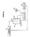
- Fig. 5 is a block diagram of the second preferred embodiment of an instrument for quantitative analysis according to the invention.
- a cell detecting unit 100 such as a microswitch is mounted on the inner wall of the cell holder 26.
- the cell detecting unit 100 is electrically connected to a control unit 110 having a microcomputer, and a light emitting diode 120 which serves to indicate to the operator that the cell 14 is set in the cell holder 26.
- a control unit 110 having a microcomputer
- a light emitting diode 120 which serves to indicate to the operator that the cell 14 is set in the cell holder 26.
- a photoelectric switch, an ultrasonic switch, other type of a sensor which can detect the position of the cell 14 without coming into contact with the cell 14 may also be used as the cell detecting unit 100.
- the detectors 66a and 66b are electrically connected to the control unit 110 and the light emitting diode 120.
- the control unit 110 is also connected to a manually operable starter switch 130 installed outside the black box 10.
- the system is made responsive to the starter switch 130 by means of the control unit 110.
- the starter switch 130 is manually operated, the sample and/or the reagent are injected into the cell 14 by means of a automatic pipetting device 140.
- the control unit 110 can also control the electromagnetic shutter 18 and the protective shutter 38.
- the other mechanical aspects of the instrument are the same as that of the first preferred embodiment of the invention.
- the handle 44 is operated to rotate the rotary shaft 40 and the rotary arm 50 so that the cell holder sliding member 56, on which the cell holder 26 is supported, slides on the shafts 60a and 60b to reach the cell setting position.
- the cell holder sliding member 56 is stopped, and the stopper 64a engages the recess of the cell holder sliding member 56.
- the detector 66a outputs a signal to the control unit 110.
- the control unit 110 judges whether or not the protective shutter 38 is closed. When the protective shutter 38 is closed, the control unit 110 outputs a pulse signal to the electromagnetic shutter 18, so that the shutter 18 opens.
- the cell 14 is then introduced into the cell holder 26 through the cell port 12a by hand or by means of an auxiliary apparatus, such as a pincette, so as to be fixed to the pan 26c.
- the cell detecting unit 100 is turned on to output a detector signal to the control unit 110.
- the handle 44 is operated to rotate the rotary shaft 40 and the rotary arm 50, so that the cell holder 26 moves in the direction of the injecting position.
- the stopper 64b engages the recess of the cell holder sliding member 56.
- the detector 66b detects that the cell holder 26 reaches the injecting position, and outputs a detector signal to the diode 120 so that the operator can recognize that the cell holder 26 is accurately positioned at the injecting position.
- the detector signal produced by the detector 66b is also outputted to the control unit 110.
- the control unit 110 judges whether or not the electromagnetic shutter 18 is closed. If the shutter 18 is closed, the control unit outputs a pulse signal to the protective shutter 38 so that the shutter 38 opens.
- the control unit 110 since the both detector signals produced by the cell detecting unit 100 and the detector 66b are inputted to the control unit 110, the control unit 110 outputs a control signal to the starter switch 130, so that the starter switch 130 is in an active state. In this state, when the starter switch 130 is operated, the automatic pipetting device 140 is turned on, so that a sample to be tested and/or a reagent are injected into the cell 14 through the Teflon tubes 22a and 22b, respectively. Light produced by mixing of the sample with the reagent in the cell 14 passes through the window 30 and impings upon the light receiving surface of the photomultiplier tube 34. The photomultiplier tube 34 detects the quantity of incident light.
Landscapes
- Chemical & Material Sciences (AREA)
- Physics & Mathematics (AREA)
- Health & Medical Sciences (AREA)
- Pathology (AREA)
- Life Sciences & Earth Sciences (AREA)
- Analytical Chemistry (AREA)
- Biochemistry (AREA)
- General Health & Medical Sciences (AREA)
- General Physics & Mathematics (AREA)
- Immunology (AREA)
- Plasma & Fusion (AREA)
- Chemical Kinetics & Catalysis (AREA)
- Engineering & Computer Science (AREA)
- Nuclear Medicine, Radiotherapy & Molecular Imaging (AREA)
- Investigating Or Analysing Materials By The Use Of Chemical Reactions (AREA)
- Optical Measuring Cells (AREA)
Applications Claiming Priority (4)
| Application Number | Priority Date | Filing Date | Title |
|---|---|---|---|
| JP1987054158U JPS63161351U (de) | 1987-04-09 | 1987-04-09 | |
| JP54158/87 | 1987-04-09 | ||
| JP97630/87 | 1987-06-25 | ||
| JP1987097630U JPH0710280Y2 (ja) | 1987-06-25 | 1987-06-25 | 定量分析装置 |
Publications (3)
| Publication Number | Publication Date |
|---|---|
| EP0286119A2 true EP0286119A2 (de) | 1988-10-12 |
| EP0286119A3 EP0286119A3 (en) | 1990-06-13 |
| EP0286119B1 EP0286119B1 (de) | 1993-12-08 |
Family
ID=26394899
Family Applications (1)
| Application Number | Title | Priority Date | Filing Date |
|---|---|---|---|
| EP88105634A Expired - Lifetime EP0286119B1 (de) | 1987-04-09 | 1988-04-08 | Quantitatives Analyseinstrument |
Country Status (4)
| Country | Link |
|---|---|
| US (1) | US5223218A (de) |
| EP (1) | EP0286119B1 (de) |
| KR (1) | KR970003276B1 (de) |
| DE (1) | DE3886081T2 (de) |
Cited By (6)
| Publication number | Priority date | Publication date | Assignee | Title |
|---|---|---|---|---|
| EP0616208A1 (de) * | 1993-03-19 | 1994-09-21 | Ciba Corning Diagnostics Corp. | Luminometer |
| FR2738344A1 (fr) * | 1995-09-04 | 1997-03-07 | Rech Investissements Sfri Soc | Luminometre notamment pour analyses medicales |
| EP0718622A3 (de) * | 1994-12-20 | 1997-07-23 | Bio Sensor Kenkyusho Kk | Verfahren und Vorrichtung zur Messung der Chemilumineszenz |
| US5686046A (en) * | 1995-07-13 | 1997-11-11 | Chiron Diagnostics Corporation | Luminometer |
| EP1021714A4 (de) * | 1997-10-09 | 2005-03-23 | Lumitest Ltd | Verfahren und vorrichtung zur messung von lipidperoxidation in biologischen flüssigkeiten und stuffsuspensionen |
| WO2005106500A1 (de) * | 2004-04-27 | 2005-11-10 | Carl Zeiss Jena Gmbh | Lichtblendenvorrichtung für mikrotestplatten |
Families Citing this family (21)
| Publication number | Priority date | Publication date | Assignee | Title |
|---|---|---|---|---|
| JP2626738B2 (ja) * | 1990-03-13 | 1997-07-02 | 三共株式会社 | 化学発光検出装置 |
| IT1256003B (it) * | 1992-07-24 | 1995-11-17 | Guido Motolese | Dispositivo elettronico di elevata sensibilita', particolarmente indicato per la misura di emissioni luminose di piccolissima intensita' |
| US5580785A (en) * | 1995-04-27 | 1996-12-03 | Lumitox Gulf L.C. | Field-portable toxicity tester |
| US5795784A (en) | 1996-09-19 | 1998-08-18 | Abbott Laboratories | Method of performing a process for determining an item of interest in a sample |
| US5856194A (en) | 1996-09-19 | 1999-01-05 | Abbott Laboratories | Method for determination of item of interest in a sample |
| US8337753B2 (en) | 1998-05-01 | 2012-12-25 | Gen-Probe Incorporated | Temperature-controlled incubator having a receptacle mixing mechanism |
| ES2286750T3 (es) * | 1998-05-01 | 2007-12-01 | Gen-Probe Incorporated | Dispositivo para agitar el contenido liquido de un contenedor. |
| US6555060B1 (en) * | 1998-10-14 | 2003-04-29 | Polaroid Corporation | Apparatus for performing diagnostic testing |
| US6495373B1 (en) * | 1998-10-14 | 2002-12-17 | Polaroid Corporation | Method and apparatus for performing diagnostic tests |
| US6328930B1 (en) * | 1999-02-11 | 2001-12-11 | Polaroid Corporation | Apparatus for performing diagnostic testing |
| US7157047B2 (en) * | 2001-02-09 | 2007-01-02 | Pss Bio Instruments, Inc. | Device for containing, reacting and measuring, and method of containing, reacting and measuring |
| US20030148536A1 (en) * | 2002-02-04 | 2003-08-07 | Chi-Wang Liang | Chemiluminescence analyzer |
| AU2004308278B2 (en) * | 2003-12-19 | 2010-10-28 | Gilson, Inc. | Method and apparatus for liquid chromatography automated sample loading |
| US7964413B2 (en) | 2005-03-10 | 2011-06-21 | Gen-Probe Incorporated | Method for continuous mode processing of multiple reaction receptacles in a real-time amplification assay |
| JP5026849B2 (ja) | 2007-04-20 | 2012-09-19 | 株式会社日立製作所 | 化学発光計測装置 |
| US9046507B2 (en) | 2010-07-29 | 2015-06-02 | Gen-Probe Incorporated | Method, system and apparatus for incorporating capacitive proximity sensing in an automated fluid transfer procedure |
| AU2012222178B2 (en) | 2011-02-24 | 2014-12-18 | Gen-Probe Incorporated | Systems and methods for distinguishing optical signals of different modulation frequencies in an optical signal detector |
| CN104089939B (zh) * | 2014-07-21 | 2016-08-17 | 深圳市奥特库贝科技有限公司 | 一种荧光测定装置及方法 |
| CN107167427B (zh) * | 2017-06-28 | 2023-04-18 | 苏州长光华医生物医学工程有限公司 | 一种单反应杯发光测量室 |
| WO2021024278A1 (en) * | 2019-08-05 | 2021-02-11 | KORDI, Tahere | A dark box for light-sensitive reactions |
| CN113009166B (zh) * | 2021-02-20 | 2023-01-24 | 重庆博奥新景医学科技有限公司 | 一种避光检测系统及其实施方法 |
Family Cites Families (11)
| Publication number | Priority date | Publication date | Assignee | Title |
|---|---|---|---|---|
| US3370175A (en) * | 1965-01-28 | 1968-02-20 | North American Rockwell | Toxicant detector |
| US3359973A (en) * | 1965-02-23 | 1967-12-26 | Hazleton Lab Inc | Bioluminescence reaction chamber |
| US3520660A (en) * | 1966-09-09 | 1970-07-14 | Nasa | Light detection instrument |
| US3756920A (en) * | 1971-04-30 | 1973-09-04 | Nasa | In biological samples my measuring light reactions automatic instrument for chemical processing to dedect microorganisms |
| US3985508A (en) * | 1975-10-28 | 1976-10-12 | Melvin Williams | Automated chemical analyzer |
| DE2737223A1 (de) * | 1977-08-18 | 1979-02-22 | Focke Pfuhl Verpack Automat | Verpackung aus trays sowie zuschnitt und verfahren zum herstellen derartiger packungen |
| CA1130107A (en) * | 1978-06-14 | 1982-08-24 | John H. Kennedy | Apparatus and method for luminescent determination of concentration of an analyte in a sample |
| US4319842A (en) * | 1980-07-17 | 1982-03-16 | Baxter Travenol Laboratories, Inc. | Photomultiplier protector for a fluorometer |
| US4396579A (en) * | 1981-08-06 | 1983-08-02 | Miles Laboratories, Inc. | Luminescence detection device |
| US4472352A (en) * | 1982-09-24 | 1984-09-18 | Biosys S.A. | Device for biochemical quantitative analysis of successive samples |
| GB8529889D0 (en) * | 1985-12-04 | 1986-01-15 | Cardiff Energy & Resources | Luminometer construction |
-
1988
- 1988-04-08 US US07/179,645 patent/US5223218A/en not_active Expired - Lifetime
- 1988-04-08 KR KR1019880003989A patent/KR970003276B1/ko not_active Expired - Fee Related
- 1988-04-08 EP EP88105634A patent/EP0286119B1/de not_active Expired - Lifetime
- 1988-04-08 DE DE88105634T patent/DE3886081T2/de not_active Expired - Fee Related
Cited By (10)
| Publication number | Priority date | Publication date | Assignee | Title |
|---|---|---|---|---|
| EP0616208A1 (de) * | 1993-03-19 | 1994-09-21 | Ciba Corning Diagnostics Corp. | Luminometer |
| AU687363B2 (en) * | 1993-03-19 | 1998-02-26 | Ciba Corning Diagnostics Corp. | Luminometer |
| EP0718622A3 (de) * | 1994-12-20 | 1997-07-23 | Bio Sensor Kenkyusho Kk | Verfahren und Vorrichtung zur Messung der Chemilumineszenz |
| US5686046A (en) * | 1995-07-13 | 1997-11-11 | Chiron Diagnostics Corporation | Luminometer |
| FR2738344A1 (fr) * | 1995-09-04 | 1997-03-07 | Rech Investissements Sfri Soc | Luminometre notamment pour analyses medicales |
| WO1997009610A1 (fr) * | 1995-09-04 | 1997-03-13 | Societe Française De Recherches Et D'investissements (S.F.R.I.) | Luminometre notamment pour analyses medicales |
| US6377342B1 (en) | 1995-09-04 | 2002-04-23 | Societe Francaise De Recherches Et D'investissements (Sfri) | Luminometer, particularly for medical assays |
| EP1021714A4 (de) * | 1997-10-09 | 2005-03-23 | Lumitest Ltd | Verfahren und vorrichtung zur messung von lipidperoxidation in biologischen flüssigkeiten und stuffsuspensionen |
| WO2005106500A1 (de) * | 2004-04-27 | 2005-11-10 | Carl Zeiss Jena Gmbh | Lichtblendenvorrichtung für mikrotestplatten |
| DE102004020591A1 (de) * | 2004-04-27 | 2005-11-17 | Carl Zeiss Jena Gmbh | Meßvorrichtung |
Also Published As
| Publication number | Publication date |
|---|---|
| DE3886081T2 (de) | 1994-04-14 |
| EP0286119B1 (de) | 1993-12-08 |
| DE3886081D1 (de) | 1994-01-20 |
| KR970003276B1 (ko) | 1997-03-17 |
| US5223218A (en) | 1993-06-29 |
| KR880013006A (ko) | 1988-11-29 |
| EP0286119A3 (en) | 1990-06-13 |
Similar Documents
| Publication | Publication Date | Title |
|---|---|---|
| EP0286119B1 (de) | Quantitatives Analyseinstrument | |
| EP0718622B1 (de) | Verfahren und Vorrichtung zur Messung der Chemilumineszenz | |
| JP3181257B2 (ja) | サンプル間のクロストークを減少させるルミノメータ | |
| US7964147B2 (en) | Hand-held analysis device | |
| US5415840A (en) | Liquid sample automatic analyzer | |
| US4406547A (en) | Apparatus for effecting automatic analysis | |
| US5139745A (en) | Luminometer | |
| US3764214A (en) | Photometer apparatus | |
| EP0446859A1 (de) | Apparat zur Detektion der chemischen Lumineszenz | |
| MX9602282A (es) | Luminimetro. | |
| EP0925495A1 (de) | Gerät zur bestimmung optischer eigenschaften von flüssigen proben | |
| CN107796808A (zh) | 一种便携式检测仪 | |
| JPWO2019013360A1 (ja) | 生体試料分析装置 | |
| US7951329B2 (en) | Rotary luminometer | |
| JPS59206744A (ja) | 遠心分析装置 | |
| US4309112A (en) | Rate measurement analyzer | |
| JPH0416205Y2 (de) | ||
| WO2014078349A1 (en) | Measuring luminescence and absorbance and apparatus therefor | |
| CA2323442C (en) | Method and apparatus for measuring proteins | |
| CA2568774A1 (en) | System and method for analyzing microbial growth | |
| EP0864867B1 (de) | Verbesserung des Analysator-Durchsatzes mittels einer Analyse an der Pipettenspitze | |
| JPH0416203Y2 (de) | ||
| JPH0710280Y2 (ja) | 定量分析装置 | |
| JP3915242B2 (ja) | 自動分析装置の測光装置 | |
| JPS5937946B2 (ja) | 検体中の微量成分分析装置 |
Legal Events
| Date | Code | Title | Description |
|---|---|---|---|
| PUAI | Public reference made under article 153(3) epc to a published international application that has entered the european phase |
Free format text: ORIGINAL CODE: 0009012 |
|
| AK | Designated contracting states |
Kind code of ref document: A2 Designated state(s): CH DE FR GB IT LI NL SE |
|
| PUAL | Search report despatched |
Free format text: ORIGINAL CODE: 0009013 |
|
| AK | Designated contracting states |
Kind code of ref document: A3 Designated state(s): CH DE FR GB IT LI NL SE |
|
| 17P | Request for examination filed |
Effective date: 19901213 |
|
| 17Q | First examination report despatched |
Effective date: 19920520 |
|
| GRAA | (expected) grant |
Free format text: ORIGINAL CODE: 0009210 |
|
| AK | Designated contracting states |
Kind code of ref document: B1 Designated state(s): CH DE FR GB IT LI NL SE |
|
| REF | Corresponds to: |
Ref document number: 3886081 Country of ref document: DE Date of ref document: 19940120 |
|
| ITF | It: translation for a ep patent filed | ||
| ET | Fr: translation filed | ||
| PLBE | No opposition filed within time limit |
Free format text: ORIGINAL CODE: 0009261 |
|
| STAA | Information on the status of an ep patent application or granted ep patent |
Free format text: STATUS: NO OPPOSITION FILED WITHIN TIME LIMIT |
|
| 26N | No opposition filed | ||
| EAL | Se: european patent in force in sweden |
Ref document number: 88105634.5 |
|
| PGFP | Annual fee paid to national office [announced via postgrant information from national office to epo] |
Ref country code: FR Payment date: 19950317 Year of fee payment: 8 |
|
| PGFP | Annual fee paid to national office [announced via postgrant information from national office to epo] |
Ref country code: GB Payment date: 19950320 Year of fee payment: 8 |
|
| PGFP | Annual fee paid to national office [announced via postgrant information from national office to epo] |
Ref country code: SE Payment date: 19950421 Year of fee payment: 8 |
|
| PGFP | Annual fee paid to national office [announced via postgrant information from national office to epo] |
Ref country code: CH Payment date: 19950519 Year of fee payment: 8 |
|
| PGFP | Annual fee paid to national office [announced via postgrant information from national office to epo] |
Ref country code: DE Payment date: 19950526 Year of fee payment: 8 |
|
| PG25 | Lapsed in a contracting state [announced via postgrant information from national office to epo] |
Ref country code: GB Effective date: 19960408 |
|
| PG25 | Lapsed in a contracting state [announced via postgrant information from national office to epo] |
Ref country code: SE Effective date: 19960409 |
|
| PG25 | Lapsed in a contracting state [announced via postgrant information from national office to epo] |
Ref country code: LI Effective date: 19960430 Ref country code: CH Effective date: 19960430 |
|
| GBPC | Gb: european patent ceased through non-payment of renewal fee |
Effective date: 19960408 |
|
| REG | Reference to a national code |
Ref country code: CH Ref legal event code: PL |
|
| PG25 | Lapsed in a contracting state [announced via postgrant information from national office to epo] |
Ref country code: FR Effective date: 19961227 |
|
| PG25 | Lapsed in a contracting state [announced via postgrant information from national office to epo] |
Ref country code: DE Effective date: 19970101 |
|
| EUG | Se: european patent has lapsed |
Ref document number: 88105634.5 |
|
| REG | Reference to a national code |
Ref country code: FR Ref legal event code: ST |
|
| PGFP | Annual fee paid to national office [announced via postgrant information from national office to epo] |
Ref country code: NL Payment date: 20010424 Year of fee payment: 14 |
|
| PG25 | Lapsed in a contracting state [announced via postgrant information from national office to epo] |
Ref country code: NL Free format text: LAPSE BECAUSE OF NON-PAYMENT OF DUE FEES Effective date: 20021101 |
|
| NLV4 | Nl: lapsed or anulled due to non-payment of the annual fee |
Effective date: 20021101 |
|
| PG25 | Lapsed in a contracting state [announced via postgrant information from national office to epo] |
Ref country code: IT Free format text: LAPSE BECAUSE OF NON-PAYMENT OF DUE FEES;WARNING: LAPSES OF ITALIAN PATENTS WITH EFFECTIVE DATE BEFORE 2007 MAY HAVE OCCURRED AT ANY TIME BEFORE 2007. THE CORRECT EFFECTIVE DATE MAY BE DIFFERENT FROM THE ONE RECORDED. Effective date: 20050408 |