EP0286236A2 - Cadre de rangement pour conteneurs en forme de boîte - Google Patents
Cadre de rangement pour conteneurs en forme de boîte Download PDFInfo
- Publication number
- EP0286236A2 EP0286236A2 EP88301971A EP88301971A EP0286236A2 EP 0286236 A2 EP0286236 A2 EP 0286236A2 EP 88301971 A EP88301971 A EP 88301971A EP 88301971 A EP88301971 A EP 88301971A EP 0286236 A2 EP0286236 A2 EP 0286236A2
- Authority
- EP
- European Patent Office
- Prior art keywords
- container
- locking member
- storage
- terminal ends
- compartmental
- Prior art date
- Legal status (The legal status is an assumption and is not a legal conclusion. Google has not performed a legal analysis and makes no representation as to the accuracy of the status listed.)
- Withdrawn
Links
- 239000000523 sample Substances 0.000 description 5
- IJGRMHOSHXDMSA-UHFFFAOYSA-N Atomic nitrogen Chemical compound N#N IJGRMHOSHXDMSA-UHFFFAOYSA-N 0.000 description 4
- 239000007788 liquid Substances 0.000 description 2
- 229910052757 nitrogen Inorganic materials 0.000 description 2
- 230000035899 viability Effects 0.000 description 2
- 239000003708 ampul Substances 0.000 description 1
- 239000012472 biological sample Substances 0.000 description 1
- 238000004113 cell culture Methods 0.000 description 1
- 238000010276 construction Methods 0.000 description 1
- 239000002184 metal Substances 0.000 description 1
- 238000000034 method Methods 0.000 description 1
- 238000012986 modification Methods 0.000 description 1
- 230000004048 modification Effects 0.000 description 1
- 229910001220 stainless steel Inorganic materials 0.000 description 1
- 239000010935 stainless steel Substances 0.000 description 1
- 238000010792 warming Methods 0.000 description 1
Images





Classifications
-
- F—MECHANICAL ENGINEERING; LIGHTING; HEATING; WEAPONS; BLASTING
- F25—REFRIGERATION OR COOLING; COMBINED HEATING AND REFRIGERATION SYSTEMS; HEAT PUMP SYSTEMS; MANUFACTURE OR STORAGE OF ICE; LIQUEFACTION SOLIDIFICATION OF GASES
- F25D—REFRIGERATORS; COLD ROOMS; ICE-BOXES; COOLING OR FREEZING APPARATUS NOT OTHERWISE PROVIDED FOR
- F25D25/00—Charging, supporting, and discharging the articles to be cooled
Definitions
- the present invention relates to storage racks and is concerned, more particularly, with a storage rack for holding a plurality of substantially box-like storage containers one above the other, capable of being used for instance in a cryogenic environment.
- a biological sample is placed in a cryogenic vial and a plurality of such vials are placed in a storage container.
- a plurality of storage containers are then placed in a rack, which is introduced into a mechanical freezer or a vessel containing a cryogenic medium, such as liquid nitrogen.
- Vessels containing liquid nitrogen preferably have a working temperature at the opening of about -150°C or below, in order to ensure the viability of frozen cells for long periods of time.
- the present invention proposes an improved rack for holding a plurality of storage containers, having means for independently locking and maintaining each of the containers within the rack, which allows quick and easy access thereto.
- a storage rack for holding a plurality of substantially box-like containers, having one above the other a plurality of storage compartmental areas each of which is capable of receiving and holding a substantially box-like storage container, characterised in that a plurality of independent locking members are provided, one locking member being associated with each of the storage compartmental areas, each locking member having a pair of terminal ends rotatably mounted to openings in the rack, a front support portion for placement in front of the container and a pair of side portions connecting the front portion to the terminal ends respectively, the locking member having means for holding it in a stationary position and also having a configuration such that, when placed in a first position, it maintains and holds the container within the storage compartmental area and, when placed in the second position, it allows entrance or removal of the substantially box-like storage container.
- a rack 10 is shown made in accordance with the present invention.
- the rack 10 has a pair of oppositely-disposed side walls 12 and a back wall 14 connecting its side walls 12.
- the rack 10 is provided with a top portion 16 and a bottom portion 17.
- a plurality of shelves 19 extend from the side walls 12.
- a pair of the shelves 19 are provided for supporting each container 22.
- the shelves 19 may extend any desired distance across the rack 10, as it is only necessary for them to support the container 22 or, if desired, a single shelf may be provided for supporting the container 22.
- each compartmental area Associated with each compartmental area is a locking member 24.
- the rack 20 may be provided with any desired number of compartmental areas.
- the top, central and bottom compartmental areas 20 each have a substantially box-like 22 container therein, which is capable of holding a sample to be stored, for example a biological cell culture.
- the container 22 may be of a conventional construction, as is currently used in the art for holding samples.
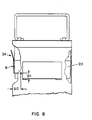
- the second and fourth compartmental areas 20, starting from the top 16, are empty. In the top compartmental area 20, the container 22 is illustrated in its fully-seated position within the rack 10 (see Figures 3 and 8) and the locking member 24 is in its closed position.
- the fully seated position is that position where the container 22 is placed as far back in its rack 10 as possible.
- the locking member 24 is shown in the fully closed position.
- a box-like container 22 is shown which has been moved forward and its locking member 24 prevents the container 22 from falling out.
- a locking member 24 is shown which is also in the fully closed position.
- the bottom compartmental area 20 is shown with a locking member 24 in its open position, whereby a box-like container 22 can be easily placed therein or removed therefrom.
- the top 16 of the rack 10 is provided with a handle 26 for lifting the rack 10 and positioning it as required within a cryogenic environment by any conventional means.
- the handle may have any shape desired.
- This locking member 24 has a pair of terminal ends 28, which are mounted to the side walls 12 of the rack 10 through an opening 30 therein (see Figure 3).
- the opening 30 is designed to be of a size sufficient to allow easy entrance and removal of the terminal ends 28, yet is not too large so as to provide an excessive amount of movement of the terminal ends 28 therein.
- the openings 30 have a diameter of approximately 0.070 inches (1.78mm) and the terminal ends 28 have a diameter of approximately 0.036 inches (0.89mm).
- the locking member 24 is made of a metal wire having a substantially circular cross-section.
- the locking member 24 is made of stainless steel.
- the locking member 24 has a front support portion 32 which engages the front of the box-like container 22, for preventing the container 22 from coming out of the compartmental area 20 when the locking member 24 is placed in a locking position.
- the front portion 32 is connected to the terminal ends 28 by side portions 34.
- the side portions comprise a first leg 36 extending from the terminal end 28 and a second leg 38, which is disposed at substantially 90° to the first leg 36 and extends substantially parallel to the plane in which the front portion 32 lies.
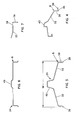
- the locking member 24 is shown in its closed position. When the locking member is in the closed position, it will prevent the box-like container 22 from simply sliding out of the compartmental area 20 unless the locking member has been moved past the locking position illustrated in Figure 9.
- a box-like container slides forward, it is stopped from any further movement once the locking member reaches its locking or equilibrium position. When the locking member is in the locking position, the sum of the horizontal and vertical forces is zero.
- the spring forces of the locking member and/or the weight of the container 22 provide a sufficient force to prevent the locking member from rotating open any further.
- the locking member is maintained in the closed or open position by the spring forces being applied at the opening 30.
- the locking member is designed such that the width W of the locking member 24 (see Figure 5) is greater than the width WR between the openings 30 (see Figure 2) inside the walls 12, so as to provide a spring force between the locking member 24 and the rack 10. This spring force will cause the locking member to stay in the position it is rotated to by the operator.
- the amount of spring force provided is sufficient to allow easy rotation of the locking member 24, yet provide sufficient force so that the locking member will not be easily moved b movement of the rack or by being jarred.
- the distance WR is approximately 3.5 inches (8.89 cm) and the width W of the locking member 24 is approximately 3.75 inches (9.525 cm).
- the width W of the locking member 24 is also such that it will accommodate the width WB of the container (see Figure 2) within the compartmental area 20.
- the opening 30 need not be provided with any other means for maintaining the locking member 24 in any position on which it is moved, the opening 30 may be provided with a detent system (not shown) for providing positive locking portions of the locking member 24.
- the opening 30 may be provided with an indented portion for receiving the leg 38 of the locking member 24 when in the locking position.
- the spring force of the locking member 24 is sufficient for maintaining the locking member 24 in the position in which it is left by the operator.
- the side portion comprises a first leg 36 and a second leg 38.
- the side portion may be a single member extending from the terminal end 28 to the point B where it meets the front portion 32.
- An important aspect of the present invention is that the distance from the terminal end 28 to the point B is such that it will allow clearing of the substantially box-like member in the fully-opened position, as illustrated in Figure 10, yet will provide the locking capabilities as illustrated in Figure 9.
- the front portion 32 of the locking member 24 is provided with a gripping portion 40 which extends away from the container 22, so as to provide means for manually gripping the locking member 24.
- a substantially box-like container 22 is initially placed within a compartmental area 20 by simply sliding a container 22 on to the shelf 18. After the container 22 has been fully seated, the locking member is rotated upward to the position illustrated in Figure 1. It is sufficient for the locking member 24 to be rotated past the locking position illustrated in Figure 9. Once the locking member is rotated past this position vertically upwards, the container will be stopped from simply sliding out of the compartmental area 20. In order to remove the container, the locking member 24 is rotated below the locking position to a point out of the path of the container. The container is then just simply pulled out. It can be seen that this operation can be done very quickly and easily by the use of a single hand.
- D1 is at least 0.25 inches (0.635cm) and preferably at least 0.375 inches (0.95cm). In the particular embodiment illustrated, D1 is about 0.4 inches (1.016cm).
- the opening 30 is also preferably positioned a distance D2 behind the front plane of the container 20 when in the fully seated position. In the particular embodiment illustrated, the distance D2 is at least 0.25 inches (0.635cm), preferably at least about 0.375 inches (0.95cm).
- D2 is about 0.4 inches (1.016cm).
- D1 is preferably equal to D2 as illustrated.
- D1 and D2 are large enough to prevent accidental falling out of the container, yet preferably not too large as to require an excessive amount of swing to rotate the locking member from the open to the locked position.
- the locking member 24 is a wire having a substantially circular cross-sectional shape; however, the present invention is not so limited.
- the locking member may take other forms, for example, the locking member may take the form of a narrow flat strip.
Landscapes
- Engineering & Computer Science (AREA)
- Chemical & Material Sciences (AREA)
- Combustion & Propulsion (AREA)
- Physics & Mathematics (AREA)
- Mechanical Engineering (AREA)
- Thermal Sciences (AREA)
- General Engineering & Computer Science (AREA)
- Details Of Rigid Or Semi-Rigid Containers (AREA)
- Packaging Of Annular Or Rod-Shaped Articles, Wearing Apparel, Cassettes, Or The Like (AREA)
- De-Stacking Of Articles (AREA)
Applications Claiming Priority (2)
| Application Number | Priority Date | Filing Date | Title |
|---|---|---|---|
| US36299 | 1987-04-09 | ||
| US07/036,299 US4771900A (en) | 1987-04-09 | 1987-04-09 | Storage rack for box-like container |
Publications (2)
| Publication Number | Publication Date |
|---|---|
| EP0286236A2 true EP0286236A2 (fr) | 1988-10-12 |
| EP0286236A3 EP0286236A3 (fr) | 1990-02-07 |
Family
ID=21887812
Family Applications (1)
| Application Number | Title | Priority Date | Filing Date |
|---|---|---|---|
| EP88301971A Withdrawn EP0286236A3 (fr) | 1987-04-09 | 1988-03-07 | Cadre de rangement pour conteneurs en forme de boíte |
Country Status (3)
| Country | Link |
|---|---|
| US (1) | US4771900A (fr) |
| EP (1) | EP0286236A3 (fr) |
| JP (1) | JPS63272663A (fr) |
Cited By (2)
| Publication number | Priority date | Publication date | Assignee | Title |
|---|---|---|---|---|
| WO1993016591A1 (fr) * | 1990-08-24 | 1993-09-02 | National Health Guard, Inc. | Stockage cryogenique de fluides perissables |
| EP0886115A3 (fr) * | 1997-06-18 | 2000-10-11 | Messer Griesheim Gmbh | Dispositif pour l'entreposage cryogénique d'échantillons pharmaceutiques |
Families Citing this family (14)
| Publication number | Priority date | Publication date | Assignee | Title |
|---|---|---|---|---|
| USD325680S (en) | 1989-05-29 | 1992-04-28 | Treston Oy | Rack for boxes |
| US5042651A (en) * | 1989-06-02 | 1991-08-27 | Lone Star Container Corporation | Stand alone disposable display |
| USD326200S (en) | 1989-08-11 | 1992-05-19 | International Business Machines Corporation | Rack for electronic equipment |
| US5111944A (en) * | 1990-05-29 | 1992-05-12 | Ostermeyer Walter H | Container station |
| US9182155B2 (en) * | 2004-12-08 | 2015-11-10 | Ethan J. Crumlin | Environmentally adaptable transport device |
| US7870748B2 (en) * | 2005-02-25 | 2011-01-18 | Byrne Kathleen H | Method for controlled rate freezing and long term cryogenic storage |
| US20090050590A1 (en) * | 2007-08-24 | 2009-02-26 | Lutgen H Michael | Storage system and methods |
| JP5749901B2 (ja) * | 2010-06-29 | 2015-07-15 | ダイダン株式会社 | 実験動物飼育用ラック装置 |
| CH704128A1 (de) | 2010-11-24 | 2012-05-31 | Liconic Ag | Lageranlage für tiefe Temperaturen und Lagerkassette für Laborobjekte. |
| US20130232998A1 (en) * | 2012-03-12 | 2013-09-12 | Thermo Fisher Scientific (Asheville) Llc | Vertical storage rack for cold storage units |
| EP2664881B1 (fr) | 2012-05-16 | 2015-01-07 | M & R Automation GmbH | Dispositif de stockage |
| US8955696B2 (en) * | 2012-06-08 | 2015-02-17 | Tina Ting-Yuan Wang | Storage systems for milk bags |
| JP6689583B2 (ja) * | 2015-07-31 | 2020-04-28 | 大陽日酸株式会社 | シート状生体試料の収納具、収納ラック及び収納棚 |
| KR102460678B1 (ko) * | 2020-12-08 | 2022-10-27 | 곽양규 | 셀 박스 이탈방지용 스토퍼를 포함하는 냉동용기 보관랙 |
Family Cites Families (17)
| Publication number | Priority date | Publication date | Assignee | Title |
|---|---|---|---|---|
| US2525551A (en) * | 1950-10-10 | Locking mechanism fob beam backs | ||
| US470050A (en) * | 1892-03-01 | Letter-file | ||
| US549212A (en) * | 1895-11-05 | Apparatus for keeping accounts | ||
| US764299A (en) * | 1904-04-07 | 1904-07-05 | Joseph J Marsh | Post-office furniture. |
| US1217973A (en) * | 1916-05-03 | 1917-03-06 | William Mann | Mail-separating device for pigeonholes. |
| US1356620A (en) * | 1920-05-14 | 1920-10-26 | Charles W Grubb | Stand for cake-boxes |
| US1702361A (en) * | 1926-11-22 | 1929-02-19 | Alton M Olinger | Display cabinet |
| US2215511A (en) * | 1939-03-17 | 1940-09-24 | Gen Motors Corp | Refrigerating apparatus |
| US3028015A (en) * | 1959-05-26 | 1962-04-03 | Dean E Williams | Garbage can holder with lid operator |
| US3388808A (en) * | 1966-03-23 | 1968-06-18 | Ready Metal Mfg Co | Collapsible display tray |
| US3669277A (en) * | 1971-02-10 | 1972-06-13 | William N Beesley Jr | Cabinet storage racks |
| US3760952A (en) * | 1971-07-01 | 1973-09-25 | J White | Display device |
| FR2215025A5 (fr) * | 1973-01-18 | 1974-08-19 | Matile Bernard | |
| US3902603A (en) * | 1974-07-01 | 1975-09-02 | Banner Metals | Retainer bar assembly for mail carrying rack |
| US4099625A (en) * | 1977-07-13 | 1978-07-11 | Leggett & Platt, Incorporated | Display rack |
| AU516931B2 (en) * | 1977-10-13 | 1981-07-02 | Amalgamated Wireless (Australasia) Limited | Shelf divider system |
| DE3342489C2 (de) * | 1983-11-24 | 1986-10-23 | Messer Griesheim Gmbh, 6000 Frankfurt | Vorrichtung zur tiefkalten Lagerung von biologischen oder pharmazeutischen Proben |
-
1987
- 1987-04-09 US US07/036,299 patent/US4771900A/en not_active Expired - Fee Related
-
1988
- 1988-03-07 EP EP88301971A patent/EP0286236A3/fr not_active Withdrawn
- 1988-04-08 JP JP63085488A patent/JPS63272663A/ja active Pending
Cited By (2)
| Publication number | Priority date | Publication date | Assignee | Title |
|---|---|---|---|---|
| WO1993016591A1 (fr) * | 1990-08-24 | 1993-09-02 | National Health Guard, Inc. | Stockage cryogenique de fluides perissables |
| EP0886115A3 (fr) * | 1997-06-18 | 2000-10-11 | Messer Griesheim Gmbh | Dispositif pour l'entreposage cryogénique d'échantillons pharmaceutiques |
Also Published As
| Publication number | Publication date |
|---|---|
| JPS63272663A (ja) | 1988-11-10 |
| EP0286236A3 (fr) | 1990-02-07 |
| US4771900A (en) | 1988-09-20 |
Similar Documents
| Publication | Publication Date | Title |
|---|---|---|
| US4771900A (en) | Storage rack for box-like container | |
| US11540510B2 (en) | Method of storing and retrieving products using cryogenic storage rack with rotatable shelves | |
| US7870748B2 (en) | Method for controlled rate freezing and long term cryogenic storage | |
| AU631160B2 (en) | Cyrogenic storage apparatus, particularly with automatic retrieval | |
| US3108840A (en) | Storage container | |
| US4840439A (en) | Display cabinet | |
| US5168725A (en) | Cryogenic storage of perishable fluids | |
| US5046624A (en) | Surgical instrument stand | |
| US6068437A (en) | Automated laboratory specimen organizer and storage unit | |
| EP2664881B1 (fr) | Dispositif de stockage | |
| CN107405257A (zh) | 冻结保存装置 | |
| US4845959A (en) | Fruits and vegetables precooling, shipping and storage container | |
| JP2018061460A (ja) | 気相式液体窒素凍結保存機器用金属製ラック | |
| EP1223393B1 (fr) | Recipient de stockage à liquide cryogénique | |
| AU2021314257B2 (en) | Canister caps for cryopreservation applications | |
| CN217837466U (zh) | 物品转移装置 | |
| Rowley et al. | Low‐temperature storage of bone marrow in nitrogen vapor‐phase refrigerators: decreased temperature gradients with an aluminum racking system | |
| US6378314B1 (en) | Cryogenic system having unique storage frames for storing bio-organic specimens | |
| CN106219014A (zh) | 抽屉式冻存管存储装置 | |
| US3052370A (en) | Apparatus for storing and dispensing materials at low temperatures | |
| JP2823458B2 (ja) | 薬用保冷庫 | |
| JP4023589B2 (ja) | 自動倉庫設備 | |
| CN220519037U (zh) | 一种交叉配血样本冷藏管理装置 | |
| CN213974988U (zh) | 多层式冷冻生物样本储存吊具和包括该储存吊具的系统 | |
| KR200303608Y1 (ko) | 생물학적 재료의 초저온 냉동 보존 베셀용 시료 홀더 |
Legal Events
| Date | Code | Title | Description |
|---|---|---|---|
| PUAI | Public reference made under article 153(3) epc to a published international application that has entered the european phase |
Free format text: ORIGINAL CODE: 0009012 |
|
| AK | Designated contracting states |
Kind code of ref document: A2 Designated state(s): BE CH DE FR GB IT LI LU NL SE |
|
| PUAL | Search report despatched |
Free format text: ORIGINAL CODE: 0009013 |
|
| AK | Designated contracting states |
Kind code of ref document: A3 Designated state(s): BE CH DE FR GB IT LI LU NL SE |
|
| STAA | Information on the status of an ep patent application or granted ep patent |
Free format text: STATUS: THE APPLICATION IS DEEMED TO BE WITHDRAWN |
|
| 18D | Application deemed to be withdrawn |
Effective date: 19900808 |