EP0286285A2 - Dispositif de fermeture pour récipient à sommet en toit - Google Patents
Dispositif de fermeture pour récipient à sommet en toit Download PDFInfo
- Publication number
- EP0286285A2 EP0286285A2 EP88302693A EP88302693A EP0286285A2 EP 0286285 A2 EP0286285 A2 EP 0286285A2 EP 88302693 A EP88302693 A EP 88302693A EP 88302693 A EP88302693 A EP 88302693A EP 0286285 A2 EP0286285 A2 EP 0286285A2
- Authority
- EP
- European Patent Office
- Prior art keywords
- panels
- panel
- roof
- foldback
- fillet
- Prior art date
- Legal status (The legal status is an assumption and is not a legal conclusion. Google has not performed a legal analysis and makes no representation as to the accuracy of the status listed.)
- Granted
Links
- 238000007789 sealing Methods 0.000 claims abstract description 65
- 239000000853 adhesive Substances 0.000 claims abstract description 63
- 230000001070 adhesive effect Effects 0.000 claims abstract description 63
- 238000000034 method Methods 0.000 claims abstract description 41
- 230000008569 process Effects 0.000 claims abstract description 39
- 229920001169 thermoplastic Polymers 0.000 claims abstract description 35
- 239000004416 thermosoftening plastic Substances 0.000 claims abstract description 35
- 239000000463 material Substances 0.000 claims abstract description 34
- 239000011324 bead Substances 0.000 claims abstract description 13
- -1 polypropylene Polymers 0.000 claims description 34
- 239000004820 Pressure-sensitive adhesive Substances 0.000 claims description 23
- 239000004743 Polypropylene Substances 0.000 claims description 18
- 238000000576 coating method Methods 0.000 claims description 18
- 229920001155 polypropylene Polymers 0.000 claims description 18
- 239000011248 coating agent Substances 0.000 claims description 14
- 239000011888 foil Substances 0.000 claims description 8
- 229920006267 polyester film Polymers 0.000 claims description 4
- 238000012546 transfer Methods 0.000 claims description 4
- 229920006289 polycarbonate film Polymers 0.000 claims description 3
- 230000032798 delamination Effects 0.000 abstract description 11
- 230000006378 damage Effects 0.000 abstract 1
- 230000004927 fusion Effects 0.000 abstract 1
- 239000012790 adhesive layer Substances 0.000 description 19
- 239000004698 Polyethylene Substances 0.000 description 16
- 229920000573 polyethylene Polymers 0.000 description 16
- 239000010410 layer Substances 0.000 description 15
- KFZMGEQAYNKOFK-UHFFFAOYSA-N Isopropanol Chemical compound CC(C)O KFZMGEQAYNKOFK-UHFFFAOYSA-N 0.000 description 9
- 230000035515 penetration Effects 0.000 description 8
- 229920000728 polyester Polymers 0.000 description 8
- 239000005038 ethylene vinyl acetate Substances 0.000 description 5
- 230000002787 reinforcement Effects 0.000 description 5
- 238000012360 testing method Methods 0.000 description 5
- XAGFODPZIPBFFR-UHFFFAOYSA-N aluminium Chemical compound [Al] XAGFODPZIPBFFR-UHFFFAOYSA-N 0.000 description 4
- 229910052782 aluminium Inorganic materials 0.000 description 4
- 230000004888 barrier function Effects 0.000 description 4
- DQXBYHZEEUGOBF-UHFFFAOYSA-N but-3-enoic acid;ethene Chemical compound C=C.OC(=O)CC=C DQXBYHZEEUGOBF-UHFFFAOYSA-N 0.000 description 4
- 239000007788 liquid Substances 0.000 description 4
- 229920001179 medium density polyethylene Polymers 0.000 description 4
- 239000004701 medium-density polyethylene Substances 0.000 description 4
- 238000004806 packaging method and process Methods 0.000 description 4
- 229920001200 poly(ethylene-vinyl acetate) Polymers 0.000 description 4
- 239000002390 adhesive tape Substances 0.000 description 3
- 230000008901 benefit Effects 0.000 description 3
- 238000010276 construction Methods 0.000 description 3
- 239000011087 paperboard Substances 0.000 description 3
- 229920005989 resin Polymers 0.000 description 3
- 239000011347 resin Substances 0.000 description 3
- 230000009471 action Effects 0.000 description 2
- 235000013361 beverage Nutrition 0.000 description 2
- 239000003795 chemical substances by application Substances 0.000 description 2
- 230000006835 compression Effects 0.000 description 2
- 238000007906 compression Methods 0.000 description 2
- 238000001816 cooling Methods 0.000 description 2
- 238000005520 cutting process Methods 0.000 description 2
- 230000002939 deleterious effect Effects 0.000 description 2
- 230000000694 effects Effects 0.000 description 2
- 238000001125 extrusion Methods 0.000 description 2
- 238000010438 heat treatment Methods 0.000 description 2
- 230000006872 improvement Effects 0.000 description 2
- 238000003780 insertion Methods 0.000 description 2
- 230000037431 insertion Effects 0.000 description 2
- 238000005259 measurement Methods 0.000 description 2
- 238000002844 melting Methods 0.000 description 2
- 230000008018 melting Effects 0.000 description 2
- 235000013336 milk Nutrition 0.000 description 2
- 239000008267 milk Substances 0.000 description 2
- 210000004080 milk Anatomy 0.000 description 2
- 239000005026 oriented polypropylene Substances 0.000 description 2
- 229920003023 plastic Polymers 0.000 description 2
- 239000004033 plastic Substances 0.000 description 2
- 230000009467 reduction Effects 0.000 description 2
- 238000003860 storage Methods 0.000 description 2
- 210000003813 thumb Anatomy 0.000 description 2
- 238000012371 Aseptic Filling Methods 0.000 description 1
- 230000000181 anti-adherent effect Effects 0.000 description 1
- QVGXLLKOCUKJST-UHFFFAOYSA-N atomic oxygen Chemical compound [O] QVGXLLKOCUKJST-UHFFFAOYSA-N 0.000 description 1
- 238000005452 bending Methods 0.000 description 1
- 230000005540 biological transmission Effects 0.000 description 1
- 230000015572 biosynthetic process Effects 0.000 description 1
- 229920002678 cellulose Polymers 0.000 description 1
- 239000001913 cellulose Substances 0.000 description 1
- 238000010960 commercial process Methods 0.000 description 1
- 239000012141 concentrate Substances 0.000 description 1
- 239000012611 container material Substances 0.000 description 1
- 230000003247 decreasing effect Effects 0.000 description 1
- 239000007888 film coating Substances 0.000 description 1
- 238000009501 film coating Methods 0.000 description 1
- 239000000796 flavoring agent Substances 0.000 description 1
- 235000019634 flavors Nutrition 0.000 description 1
- 239000012530 fluid Substances 0.000 description 1
- 235000013305 food Nutrition 0.000 description 1
- 235000015203 fruit juice Nutrition 0.000 description 1
- 239000007789 gas Substances 0.000 description 1
- 238000004519 manufacturing process Methods 0.000 description 1
- 239000000155 melt Substances 0.000 description 1
- 244000005700 microbiome Species 0.000 description 1
- 238000005065 mining Methods 0.000 description 1
- 239000000203 mixture Substances 0.000 description 1
- 125000005375 organosiloxane group Chemical group 0.000 description 1
- 239000001301 oxygen Substances 0.000 description 1
- 229910052760 oxygen Inorganic materials 0.000 description 1
- 239000000123 paper Substances 0.000 description 1
- 230000005855 radiation Effects 0.000 description 1
- 230000003014 reinforcing effect Effects 0.000 description 1
- PYWVYCXTNDRMGF-UHFFFAOYSA-N rhodamine B Chemical compound [Cl-].C=12C=CC(=[N+](CC)CC)C=C2OC2=CC(N(CC)CC)=CC=C2C=1C1=CC=CC=C1C(O)=O PYWVYCXTNDRMGF-UHFFFAOYSA-N 0.000 description 1
- 229940043267 rhodamine b Drugs 0.000 description 1
- 238000000926 separation method Methods 0.000 description 1
- 239000011343 solid material Substances 0.000 description 1
- 239000012815 thermoplastic material Substances 0.000 description 1
- 239000011800 void material Substances 0.000 description 1
- XLYOFNOQVPJJNP-UHFFFAOYSA-N water Substances O XLYOFNOQVPJJNP-UHFFFAOYSA-N 0.000 description 1
Images



Classifications
-
- B—PERFORMING OPERATIONS; TRANSPORTING
- B65—CONVEYING; PACKING; STORING; HANDLING THIN OR FILAMENTARY MATERIAL
- B65D—CONTAINERS FOR STORAGE OR TRANSPORT OF ARTICLES OR MATERIALS, e.g. BAGS, BARRELS, BOTTLES, BOXES, CANS, CARTONS, CRATES, DRUMS, JARS, TANKS, HOPPERS, FORWARDING CONTAINERS; ACCESSORIES, CLOSURES, OR FITTINGS THEREFOR; PACKAGING ELEMENTS; PACKAGES
- B65D5/00—Rigid or semi-rigid containers of polygonal cross-section, e.g. boxes, cartons or trays, formed by folding or erecting one or more blanks made of paper
- B65D5/40—Rigid or semi-rigid containers of polygonal cross-section, e.g. boxes, cartons or trays, formed by folding or erecting one or more blanks made of paper specially constructed to contain liquids
-
- B—PERFORMING OPERATIONS; TRANSPORTING
- B65—CONVEYING; PACKING; STORING; HANDLING THIN OR FILAMENTARY MATERIAL
- B65D—CONTAINERS FOR STORAGE OR TRANSPORT OF ARTICLES OR MATERIALS, e.g. BAGS, BARRELS, BOTTLES, BOXES, CANS, CARTONS, CRATES, DRUMS, JARS, TANKS, HOPPERS, FORWARDING CONTAINERS; ACCESSORIES, CLOSURES, OR FITTINGS THEREFOR; PACKAGING ELEMENTS; PACKAGES
- B65D5/00—Rigid or semi-rigid containers of polygonal cross-section, e.g. boxes, cartons or trays, formed by folding or erecting one or more blanks made of paper
- B65D5/02—Rigid or semi-rigid containers of polygonal cross-section, e.g. boxes, cartons or trays, formed by folding or erecting one or more blanks made of paper by folding or erecting a single blank to form a tubular body with or without subsequent folding operations, or the addition of separate elements, to close the ends of the body
- B65D5/06—Rigid or semi-rigid containers of polygonal cross-section, e.g. boxes, cartons or trays, formed by folding or erecting one or more blanks made of paper by folding or erecting a single blank to form a tubular body with or without subsequent folding operations, or the addition of separate elements, to close the ends of the body with end-closing or contents-supporting elements formed by folding inwardly a wall extending from, and continuously around, an end of the tubular body
- B65D5/067—Gable-top containers
Definitions
- This invention relates to packaging, and particularly to an improved package construction using a pressure sensitive adhesive tape material to improve the opening characteristics of a disposable gable-top container suitable for the packaging of liquids. More particularly, this invention relates to a blank from which the container is formed.
- Containers for beverages such as milk, fruit juices, and drinks are conventionally constructed from blanks of thermoplastic coated paperboard.
- the most widely used of such containers have a rectangular cross-sectional body surmounted by a gable-top closure incorporating an extensible pouring spout.
- Blanks from which the containers are constructed are divided into a plurality of panels which are adapted to form the walls and closure members. The panels are formed and separated by score lines at which the blank is folded. Particular panels are intended to be joined together in a lapped arrangement in the completed container. Typically, those panels are pressed together and heated or exposed to high frequency radiation to fuse the adjoining thermoplastic surfaces and form a generally strong seal.
- Containers of this type are opened for access to the contents by a two-step toggle action process.
- the gable edges are forced backward past the point at which the lip panels are joined, to nearly touch the roof panels.
- the gable edges are pushed forward and inward.
- the forces are communicated through spout panels to the tip of the pouring spout, breaking the seal between the lip panels and the underside of the roof panels and snapping the spout outward to a pouring position.
- thermoplastic coatings or foil adds some stiffness to the panels, and the container is made resistant to wicking by liquids.
- the strong bonding of the lip panels results in buckling, tearing and delamination of the cardstock upon opening the seal.
- the spout is difficult to open, and the opened panels are unappealing in appearance.
- Polyethylene has a low modulus of elasticity, so that the stiffness added by the coating is minimal.
- hermetic refers to a container designed and intended to be secure against the entry of oxygen which degrades flavor.
- the term is also used to designate containers used for aseptic filling and storage, i.e. containers secure against the entry of microorganisms.
- the hermetic barrier of such cartons typically comprises an aluminum or other barrier film coating the inner surface, overcovered with a thermoplastic such as polyethylene. The carton wall thickness is thus increased, resulting in larger channels where the edges of overlying panels have a stepped relationship in the gable rib area, increasing the chance for leakage.
- perforations in the spout panels has generally been unsatisfactory. Such perforations produce a spout of reduced size, which requires special sealing operations.
- the perforations are considered by some to be a weak point in the carton, prone to develop leaks.
- This type of carton spout requires external forces such as thumbnail pressure to open, and this procedure is considered unsanitary. The carton cannot be effectively closed, once opened, and shaking of the carton results in spillage.
- novel scoreline patterns generally has not overcome the strong sealing forces of well-sealed spouts and buckling of the spout panels is common.
- U.S. Patent No. 3,270,940 discloses the use of anti-adhesive composition applied to both the outside and inside surfaces of the pouring lip of a gable-top container.
- Abhesive agents disclosed include cellulose plastic laminated to polyethylene, the latter heat-bondable to the polyethylene surface of the cardstock blank.
- the release properties of abhesives are generally affected by the heat sealing parameters and are inconsistent.
- Containers designed for hermetic use and having adhesives in the spout sealing area often require opening forces greater than the wall strength of the panels, and the spout panels buckle during the opening process.
- the present invention is directed to an improvement in the formation of a package of paneled flexible material to stiffen the package material adjacent the sealed area to be opened.
- the result is a more reliable, consistently openable hermetically sealed opening for gaining access to the contents.
- the flexible material may be cardstock plastic, or other material with a thermoplastic inner surface coating which is sealed by elevated temperature and pressure.
- the flexible material may include a gas-impermeable film or foil layer.
- a blank of the package material with scoreline-defined panels is folded into the package shape and overlying panels are sealed.
- a typical sealing process consists of heating with hot air to a temperature which melts or fuses the thermoplastic surface coatings, and compressing together the panels to be joined.
- a container body having sides, a bottom and a top suitable for the packaging of liquids.
- the container body in the illustrated embodiment includes a front body panel, a back body panel and first and second side panels.
- Bottom closure panel means is provided for closing the bottom of the gable-top container.
- Connected to the upper edges of the first and second side panels are the first and second roof panels, respectively.
- the roof panels When assembled, the roof panels are oppositely disposed to converge upwardly, and are connected at their top edges to form a gable roof.
- the front edges of the roof panels have score lines defining subpanels which comprise first and second roof wing panels.
- the wing panels form the rear portion of the pouring spout.
- First and second opposed, substantially triangular end panels are connected to the upper edges of the front and back body panels to extend upwardly therefrom.
- the first triangular end panel, the first and second under panels and the panels listed below form an extensible pouring spout connected to the top of the container body.
- a first foldback panel is connected to the first roof wing panel and to one lateral edge of the first triangular end panel.
- a second foldback panel is connected to the second roof wing panel and to the other lateral edge of the first triangular end panel.
- a third foldback panel is connected to the other end of the first roof panel and to one lateral edge of the second triangular end panel.
- a fourth foldback panel is connected to the other lateral edge of the second triangular end panel, and is adapted to be connected to the second roof panel, opposite the second foldback panel.
- First and second gable rib panels are connected to the upper edges of the first and second foldback panels, respectively, and extend upwardly therefrom. These gable rib panels are also connected to each other at a common line, and comprise lips of the pouring spout from which the container contents are discharged.
- Third and fourth gable rib panels are connected to the upper edges of the third and fourth foldback panels, respectively, and extend upwardly therefrom.
- First and second roof rib panels are connected to the upper edges of the first and second roof panels, respectively, and extend upwardly therefrom.
- Each roof rib panel is connected at one side thereof to one of the first and second gable rib panels.
- First and second upper rib panels are connected to the upper edges of the first and second roof rib panels, respectively, and extend upwardly therefrom.
- At least one stiffening or reinforcement fillet overlays a portion of, and is bonded to, the inner surface of at least one of the following pouring spout panels: (i) first gable rib panel, (ii) second gable rib panel, (iii) first roof rib panel, (iv) second roof rib panel, (v) first triangular end panel, (vi) first foldback panel, (vii) second foldback panel, (viii) first wing panel, and (ix) second wing panel.
- the fillet comprises (a) a strip of material resistant to deleterious effects of the conventional carton sealing process, i.e. it will not melt, or otherwise degrade at the temperature and pressure of the sealing process, and (b) a layer of adhesive attached to one side of the strip.
- the layer of adhesive adheres to the inner surface of at least one of the above panel(s), strongly bonding one side of the strip to the panel or panels.
- the layer of adhesive is preferably adapted to be partially extruded from the fillet during the carton sealing process, forming a bead of extruded adhesive along the edge of the strip. This adhesive bead effectively bonds opposing pouring spout panels together with the exposed portions of the rib panels which become thermally bonded, provides a hermetic seal. This bead, however, may be disrupted without tearing, buckling or delamination of the panels.
- the fillet extends along a major portion of the force transmission line between the site where the opening force is applied and the intersection of the panels which receive the opening force.
- the fillet strengthens the panel member to which it is bonded, so that the resistance of the panel member to bending or buckling increases, and greater opening forces are transmitted to the spout tip.
- the fillet controls the force required to break the hermetic seal between panel members, so that the required opening force is less than the force which will buckle or delaminate the panels.
- the sealing force is controlled by: (a) controlling the area and specific locations of the panels which will be subject to thermoplastic heat-sealing, (b) controlling the adhesion between the resistant strip and both panels, and (c) controlling the thickness of the adhesive layer of the fillet for optional extrusion from the fillet, to adhesively join opposing panels in the pouring spout.
- the force required is limited to a value below that which will tear, delaminate, or crumple the pouring spout panels.
- a gable-top container is formed from a blank of paperboard or other suitable material coated on the inner planar surface, or on both the inner and outer surfaces with a thermoplastic material.
- the container blank is adapted to be erected and have certain panels sealed to each other by a container sealing process.
- the sealing process consists of compressing together the panels to be joined while those panels are at an elevated temperature.
- Other alternative sealing processes may also be utilized.
- FIG. 1 shows a typical container 1 in a closed, sealed condition as for storage of beverages and the like.
- the container is self-sustaining in shape and is hermetically sealed.
- Container 1 is comprised of a series of panels, including a container body having four body panels 2-5. Front body panel 4 and second side body panel 5 are shown in FIG. 1, while rear body panel 2 and first side body panel 3, not shown, oppose panels 4 and 5, respectively, forming a container of rectangular cross-section. Usually, the cross-section is square.
- the bottom of the container 1 is closed.
- First roof panel 28 is connected to the upper edge of first side panel 3.
- Second roof panel 30 is connected to the upper edge of second side panel 5.
- the roof panels 28 and 30 converge upwardly to form a gable roof construction.
- Roof rib panel 54 is attached to roof panel 30 and extends upwardly therefrom.
- upper rib panel 55 is attached to roof rib panel 54 and extends upwardly therefrom.
- First triangular end panel 29 is connected to the upper edge of the front body panel 4. When the container is closed, end panel 29 is folded under the gable roof formed by the two roof panels. Also shown are first roof wing panel 40 and second roof wing panel 43. The roof wing panels 40 and 43 are subpanels of roof panels 28 and 30, respectively. A second triangular end panel, not shown in this figure, is usually adapted to remain folded under the opposite gable roof, unless it is desired to open both gable ends of the container.
- FIG. 2 shows the container of FIG. 1 in which the spout has been partially opened.
- the first and second foldback panels 41 and 42 and overlapping roof wing panels 40 and 43 are typically pushed outward and backward with thumb pressure to break the seal between the inner surfaces of the first and second upper rib panels 49 and 55, and between the outer surfaces of the first and second gable rib panels 50 and 52, the latter not visible in this drawing.
- the gable rib panels are connected to the upper end of foldback panels 41 and 42, and extend upwardly therefrom.
- FIG. 3 shows the container at the point where foldback panels 41 and 42 have been pushed backward about 90 degrees from their sealed position. These panels are roughly triangular in shape, each having one edge defined by scoreline 35 or 36, where they are attached to a lateral edge of first triangular end panel 29.
- First and second gable rib panels 50 and 52 act as lips of the pouring spout, and meet at a common gable rib score line 51.
- the upper terminus 51A of the common rib score line at the free edge 53 of the pouring lip comprises the tip of the pouring spout.
- First and second upper rib panels 49 and 55 extend upwardly from the first and second roof rib panels 48 and 54 to a level higher than the free upper edge 53 of gale rib panels 50 and 52.
- foldback panels 41 and 42 are pushed backward beyond the position shown in FIG. 3.
- the roof rib panels and upper rib panels will fold along foldline 57.
- the blank may or may not be scored at that location.
- the gable rib panels are slightly longer than the roof rib panels.
- a subsequent forward and inward movement of wing panels 40 and 43 transmits opening forces in a toggle-like action along the wing panels and gable rib panels 50 and 52 toward the common line 51 between the gable rib panels.
- a component of these forces extends outward and upward from line 51 and from gable score lines 35 and 36 to pull the gable rib panels 50 and 52 away from roof rib panels 54 and 48, the latter not visible in FIG. 3, and to pull foldback panels 41 and 42 away from roof wing panels 40 and 43.
- triangular end panel 29 is forced outward, and the distended panels create a pouring spout.
- the various score lines delineating the panels act as hinges for the panels as they are unfolded.
- the sealing forces which bond the gable rib panels to the roof rib panels are preferably only as high as required to maintain the hermetic seal. Excessive bonding forces will require greater stiffness in the spout panels to prevent crumpling of the panels during the opening process.
- Certain features of this invention will produce a liquid-proof spout seal which is easily opened without tearing, delamination, or buckling of the spout panel members. These features underlie the spout panel members in FIG. 3, and are not visible in that figure. These features include one or more fillets 56, shown in FIG. 4 and described in reference to the remainder of the figures.
- FIG. 4 illustrates an exemplary flat sheet material blank of this invention for constructing a gable-top container.
- the inner surface or face is shown, and it is coated with a thermoplastic such as polyethylene.
- the outer surface may also be similarly coated.
- the sheet material may include a gas impermeable layer such as aluminum foil.
- An appropriate pattern of score lines divides blank 1A into a plurality of panels and sub-panels which are used as walls of the container and its closure parts when the container is erected.
- the central portion of blank 1A comprises four body panels 2, 3, 4, and 5, having their lower edges along bottom score line 13, and their upper edges along top score line 31. These transverse score lines are shown as extending from blank edge 6 to opposite blank edge 12 in substantially parallel relationship across the face of the blank. Vertical score lines 7, 8 and 9 transect the blank to define the lateral edges of the body panel 2, 3, 4 and 5, and other panels above the body panels. These and other score lines are not necessarily straight, but may be slightly offset in certain sectors of the blank to improve the fit of the various panels in the erected container.
- bottom closure means 26 is shown as a group of bottom closure panels 14 through 21 attached to the body members along bottom score line 13, and extending downward therefrom.
- Bottom closure score lines 22 through 25 enable bottom closure panels 14, 16, and 18-21 to be folded under closure panels 15 and 17 and sealed to provide a leakproof container bottom.
- a separately formed structure may alternatively be used to close the bottom of the container. In fact, any closure means which results in a satisfactorily tight seal may be used.
- the gable top of the container is formed from a series of panels above top score line 31.
- First and second roof panels 28 and 30 are connected to the upper edges of the first and second side panels 3 and 5, respectively.
- the roof panels are oppositely disposed and when erected, converge upwardly to meet along score line 44 to form a gable roof.
- Connected to the upper edge of the front panel 4 is a first substantially triangular end panel 29 whose two lateral edges 35 and 36 formed by score lines extend upwardly to score line 44.
- second triangular end panel 27 is connected to the upper edge of back panel 2, and has lateral edges 32 and 33 which extend upwardly to score line 44.
- First foldback panel 41 is connected to triangular end panel 29 along edge 35, and to first roof wing panel 40 along score line 8. Panel 41 has a score line 44 as its upper edge.
- second foldback panel 42 is connected to triangular end panel 29 along edge 36, and to second roof wing panel 43 along score line 9. It has score line 44 as its upper edge.
- third and fourth foldback panels 39 and 38 are connected to triangular end panel 27 along lateral edges 33 and 32, respectively.
- the third foldback panel 39 is attached to the first roof panel 28 along score line 7, and the fourth feedback panel 38 is connected to the second roof panel 30 by side seam flap 11 when the container is erected.
- each foldback panel 38, 39, 41 and 42 along score line 44 is a gable rib panel 45, 46, 50 and 52, respectively.
- first and second roof rib panels 48 and 54 are attached to the upper edge of first and second roof rib panels 48 and 54, respectively.
- First and second gable rib panels 50 and 52 are connected to each other at a common score line 51
- third and fourth gable rib panels 46 and 45 are connected to each other at common score line 47.
- the uppermost end 51A of line 51 is the tip of the pouring spout of the erected container.
- First gable rib panel 50 is connected to first roof rib panel 48 at score line 8
- second gable rib panel 52 is connected to second roof rib panel 54 at score line 9.
- First roof wing panel 40 comprises a triangular portion of first roof panel 28 defined by score lines 34, 44 and 8, and is adjacent first foldback panel 41.
- Second roof wing panel 43 comprises a triangular portion of second roof panel 30 defined by score lines 37, 44 and 9 and is adjacent second foldback panel 42. These roof wing panels are more or less coextensive with the adjacent foldback panel when the erected container is closed.
- a first upper rib panel 49 is connected to the upper edge of the first roof rib panel 48.
- a second upper rib panel 55 is connected to the upper edge of the second roof rib panel 54.
- the score lines 60 and 61 separate the upper rib panels from the adjacent roof rib panels, and are substantially continuous with the free upper edge 53 of the first and second gable rib panels 50 and 52. The latter panels serve as lips of the pouring spout of the erected container.
- the score lines may be applied to blank 1A before or after the thermoplastic coating is applied to the blank.
- the score lines may be applied to either surface or both surfaces of the blank. For purposes of clearer delineation of the various panels, score lines are shown in the drawings on either or both of the inner and outer surfaces of the blank and container.
- two stiffening fillets 56 overlie portions of the first and second gable rib panels 50 and 52, and extend downwardly to overcover portion of the first and second foldback panels 41 and 42 and small upper portions of first end panel 29.
- each fillet 56 comprises a strip 66 of material resistant to the container sealing process, and a layer 72 of adhesive.
- This adhesive layer 72 is attached to (a) a first planar surface 67 of strip 66 and to (b) the inner thermoplastic surface 62 of one or more of (i) the first gable rib panel 50, (ii) the second gable rib panel 52, (iii) the first roof rib panel 48, and (iv) the second roof rib panel 54, (v) the first triangular end panel, (vi) the first fold back panel, (vii) the second fold back panel, (viii) the first wing panel, the (ix) the second wing panel.
- the strip 66 of material is thus sealed to the thermoplastic inner surface 62 of one or more of these panels.
- Strip 66 may be formed from any solid material which is resistant to any deleterious effect of the container sealing process, and is sufficiently rigid so that, together with adhesive layer 72, it provides sufficient strength to reinforce the panel to achieve the necessary stiffness.
- the bond strength between the adhesive-free surface 68 of strip 66 to the thermoplastic coating must be significantly less than the bond strength between the strip 66 and the adhesive layer 72, or between the adhesive layer 72 and the strip 66.
- strip 66 must not melt, extrude, or otherwise degrade at the temperature and pressure conditions of the container sealing process.
- a container sealing process of significant compression of the panels at an elevated temperature may tend to increase the area of intimate contact and relieve elastic stresses, causing adhesive of strip 66 to the thermoplastic inner surface 62.
- the adhesive strength of this pressure-produced bond will be significantly less than the adhesive strength of the adhesive layer 72, however.
- thermoplastic coatings are typically sealed at temperatures of 250 to 400°F (81 and 205°C).
- the material of the strip may also be constructed from unoriented polypropylene, such as that utilized as a film backing in a pressure sensitive adhesive tape marketed under the trademark "Y-8450" by Minnesota Mining and Manufacturing Company of St. Paul, Minnesota.
- a fillet constructed of unoriented polypropylene exhibits several advantages over strips constructed of other materials and specifically polyester. Specifically, unoriented polypropylene has a lower modulus of elasticity than polyester (i.e. as low as 0.2 x 10⁶ps1). Therefore, a more compliant strip may be constructed which is better able to conform to the scorelines between the pouring spout panels. Thus, a notch, such as is shown in Figures 9, 10 and 12 and discussed hereinafter, is not required.
- Unoriented polypropylene is the preferred material for the strip in that it is dimensionally stable, even when subjected to the elevated temperatures and pressures experienced when a container is sealed. Oriented polypropylene, although having increased tensive strength, has a tendency to return to its unoriented state when exposed to temperatures (i.e., 180 ⁇ -200 ⁇ F) below the sealing temperatures. This distortion of oriented polypropylene results in buckling and separation of the polypropylene from a mounting surface.
- the strip 66 and adhesive layer 72 may be preformed as a tape which is applied by machine to the blank 1A.
- the modulus of elasticity of strip 66 may be as low as 0.2 x 10⁶ psi (1.4 x 10⁸ kg/m2), but preferably for materials other than polypropylene is at least 0.4 x 10⁶ psi (2.8 x 10⁸ kg/m2).
- the layer 72 is of such an adhesive type and thickness than when the fillet 56 is compressed between gable rib panel 50 and 52 and roof rib panels 48 and 54 during the first sealing process, a portion of the adhesive of layer 72 extrudes from between the panel or panels and strip 66 of resistant material.
- the extruded adhesive fills channels otherwise open to leakage and effectively seals the container.
- the adhesive used may be sealable by pressure, heat, or other process.
- FIG. 6 is an enlarged cross-sectional view through the rib portion of a container formed from this invention, showing the panel members and fillet exaggerated in thickness for the sake of clarity. It is understood that all of the panel members shown include a thermoplastic coating on at least the inner surfaces, and preferably on both the inner and outer surfaces. Additionally, the panel members may include a film or foil of gas-impermeable material such as aluminum, overcovered by the thermoplastic coating.
- First and second roof rib panels 48 and 54 overlie first and second gable rib panels 50 and 52.
- the gable rib panels are separated from foldback panels 41 and 42 by scorelines 44, and the roof rib panels are likewise separated from roof wing panels 40 and 43 by scorelines 44.
- Upper rib panels 49 and 55 are separated by score lines 60 and 61 from the roof rib panels 48 and 54, and extend upwardly therefrom.
- Each of the panels shown in the figure includes a coating of thermoplastic on at least the inner surface.
- Stiffening fillet 56 is shown attached to the inner face of gable rib panels 50 and 52, and to an upper portion of foldback panels 41 and 42.
- the fillet includes resistant strip 66 and adhesive layer 72.
- Fillet 56 may comprises a tape having a relatively thick backing or strip 66 of a stiff material whose bond to the thermoplastic surface of the panels is weaker than its bond to adhesive layer 72.
- the adhesive layer 72 may be thermoplastic in nature, but preferably is a pressure-sensitive adhesive. The latter affords easier positioning during application to the blank 1A, and does not require the application of heat for positioning.
- the thermal carton sealing process has been found to significantly enhance the sealing strength of the pressure-sensitive adhesives (PSA's) which were tested.
- PSA's pressure-sensitive adhesives
- Typical pressure sensitive adhesives can be formed into stable thick layers at room temperature, and will readily extrude at the temperatures and pressures used to thermally seal polyethylene. Thus, when an extruded bead of adhesive is desired, PSA's appear to work well.
- the container contents occupy the space between panel 40 and panel 41, and the space between panel 42 and panel 43.
- the upper rib panels, the gable rib panels, and the roof rib panels are heated to the softening or melting point of the thermoplastic coating, and compressed together as shown in FIG. 6.
- the upper rib panels are bonded on their inner surfaces at interface 69, and gable rib panels 50 and 52 are preferably mutually bonded on their outer surfaces at interface 70.
- a further sealing feature may be produced if desired.
- a thick layer 72 of an extrudable adhesive may be used in the fillet. Compression at an elevated temperature during the carton sealing process extrudes the adhesive from between the gable rib panels and strip 66, and the extruded bead 79 of adhesive bonds overlying panels 50 and 52 just above the upper edge 75 of strip 66.
- a similar extrusion of adhesive is produced along the lateral edges of strip 66 as well, both where the gable rib panels and roof rib panels are joined, and along the exposed portion of the common gable rib score line. A hermetic seal is achieved where the adhesive extrudes, even when the bead of extruded adhesive is minimal.
- the quantity of extruded adhesive may be varied by controlling the type of adhesive, the thickness of the adhesive layer, and the temperature and pressure of the carton sealing process.
- the quantity of extruded adhesive may be controlled to fill the small channels 73 or channel 74 which typically develop along the free upper edge 53 of the gable rib panels.
- the space at the tip of the pouring spout that is, the space between common line 51 and the corresponding line 47 of the third and fourth gable rib panels, usually not securely sealed in the prior art by the first sealing process, may also be controllably filled with a bead of extruded adhesive during the carton sealing process to provide an aseptic or essentially hermetic seal. This seal is especially enhanced by features to be later described.
- the adhesion of strip 66 to the container panel should preferably produce a peel strength greater than 50 oz. per inch of width (612 grams per cm. width) at room temperature, so that the fillet will remain an integral part of the panel to which it is attached, both before and after the spout panels are unsealed and unfolded.
- the fillet may be adhesively attached to at least one of the pouring spout panels listed above, depending upon what is desired for the particular application.
- Fillets adhered to the roof rib panels are somewhat less effective at transferring the opening forces than fillets adhered to the gable rib panels.
- the concomitant reduction in required opening force enables fillets on the roof rib panels to transfer the required forces.
- the thickness of adhesive layer 72 is considerably greater than would be required for merely bonding strip 66 to a panel.
- this invention generally requires an adhesive layer exceeding 0.001 inch (0.0025 cm) in thickness for achieving desired additional stiffness and leakproof hermetic sealing.
- An adhesive layer of about 0.002 inch (0.005 cm) has proven optimal for certain pressure sensitive adhesives used to seal polyethylene coated containers. With other adhesives, a thickness of up to 0.004 inch (0.0102 cm) may be used.
- an adhesive layer of approximately 0.003 inches (0.008cm) has been found to be preferred.
- FIG. 7 shows a gable-top container 1 formed from the blank of FIG. 4 and sealed according to the container sealing process, and subsequently opened from the closed and sealed condition.
- Second roof panel 30 and first roof panel 28 converge upwardly so that their upper edges 44 meet or almost meet.
- Roof rib panels 48 and 54 are sealed along approximately one-half of the length of the rib structure, and enclose third and fourth gable rib panels 45 and 46.
- common scoreline 47 between the third and fourth gable rib panels is somewhat spaced from common scoreline 51.
- the void between those scorelines is a vertical channel which when filled with adhesive will prevent leakage.
- First and second upper rib panels 49 and 55 are joined by the container sealing process.
- the spout panels of the rib structure are shown to have been opened by first breaking the seal between the upper rib panels 49 and 55, and then breaking the seal between gable rib panels 50, 52 and roof rib panels 48, 54.
- First triangular end panel 29, and first and second foldback panels 41 and 42 are folded outward to extend the pouring spout.
- Stiffening fillet 56 is shown at the inside of the pouring spout, overlying and attached to a portion of the inside surface of the first gable rib panel 50 and the second gable rib panel 52, not visible in this view. Conforming to a preferred embodiment, the fillet 56 also extends downward over scoreline 44 to overcover a portion of foldback panels 41 and 42. The advantages of such extension will be later described.
- Fillet 56 is shown as spaced from roof wing panel 40 and roof rib panel 48 to form side spacing 59, and also spaced from the free upper edge 53 of gable rib panel 50 to form lip spacing 58.
- a portion of the adhesive is extruded from the adhesive layer of the fillet 56 into channels 73, previously described, resulting from spacings 58 and 59, to effectively seal these areas from leakage.
- the surface 68 of the fillet 56 which has no adhesive layer is, of course, in contact with roof rib panels 48 and 54 when the carton is sealed.
- Fillet 56 being resistant to the container sealing process, does not strongly adhere to the thermoplastic surfaced roof rib panels, although the pressures and temperatures typical of the first sealing process minimally result in a close conformity of their surfaces which is subsequently maintained by the tight seal of the rib panel members.
- a hermetic seal results from (a) the thermoplastic heat seal between exposed portions of the gable rib panels and opposing roof rib panels, or (b) a bead of adhesive extruded from beneath the strip, to be described later, or (c) a combination of the two.
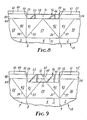
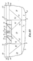
- FIGS. 8 through 12 show a portion of the blank 1A, including those panels which become the pouring spout. These figures depict various embodiments of fillet 56 in terms of the particular panel area or areas covered thereby.
- a single fillet 56 overcovers all or a portion of both gable rib panels 50 and 52.
- the uppermost edge of fillet 56 may be generally continuous with the upper free edge 53 of the gable rib panels, but is preferably spaced therefrom by less than 0.15 inches (0.38 cm) when a bead of extruded adhesive is to be a part of a hermetic seal of the container.
- an excessive sealing area for the thermoplastic carton sealing process may result. This produces a strong seal which may require an excessive opening force to break the seal. Also extruded adhesive may not reach and fill the narrow channel which generally forms above the edge 53.
- the narrow spacing 58 provides space which in some cases is desirably filled with extruded adhesive, minimizing the thermoplastic-to-thermoplastic seal area and substituting an extruded adhesive seal.
- the relatively narrow band of adhesive provides a tight seal between the gable rib and roof rib panels which is nevertheless openable with an acceptable opening force.
- the heat sealing process will bond the exposed portions of the strips 66 on each gable rib panel to each other.
- the amount of adhesive extruded into the space above the strips 66 may be decreased. Therefore, it is generally desirable to limit such upward extension of the fillet or fillets above the gable rib panels 50 and 52 to not more than 0.15 inches (0.38 cm).
- Each end of the fillet 56 may be spaced from the roof rib panels 48 and 54 to form spaces 59.
- the spacing provides room for the panels to fold around the fillet at scorelines 8 and 9.
- the spacing 59 between fillet 56 and the roof rib panels is not less than 0.01W, where W is the length of the first or second gable rib panel 50 or 52.
- the maximum spacing 59 is controlled by the length of fillet which will provide the desired stiffness to the panels, and may be as great as 0.6W, where W is as defined above.
- FIG. 9 illustrates a fillet 56 overcovering a portion of the gable rib panels 50 and 52, and extending downwardly to overlie in bonded relationship a portion of the first and second foldback panels 41 and 42.
- the fillet also optionally overlies the upper portion of first triangular end panel 29.
- the advantage of this downward extension 71 is evident when the container sealing process is one which affects the bonding strength of the fillet adhesive layer.
- heat is directly applied to the panels to be sealed, i.e., the rib panels. Panels below the rib panels are only incidently heated and attain a considerably lower temperature.
- the sealing temperature is difficult to accurately control, and if the fillet adhesive softens excessively, the fillet strip may slide downward, not retaining its proper alignment on the gable rib panel or panels.
- the portion of the fillet below the gable rib panels will be much less affected because of the lower temperature, and will maintain the original position of the fillet.
- the high adhesion of adhesive layer 72 is regained upon cooling.
- the figure also shows the fillet as overlying score line apex 64 at the top of triangular end panel 29.
- strip 66 may include a cut extending downwardly from the upper edge of the strip, along at least a portion of the common line 51. This enables adhesive from layer 72 and/or melted thermoplastic polyethylene to extrude through the cut, notch or slot to contact the opposite gable rib panels 45 and 46 at common scoreline 47, and bond thereto. This difficult-to-seal site is thus effectively sealed.
- Fillet 56 is further shown in FIG. 9 with a notch 65 extending downwardly from the upper edge of the strip, along the common line 51 between the first gable rib panel 50 and the second gable rib panel 52.
- the notch may optionally extend downwardly to expose apex 64, as further shown in FIG. 10, or may extend downwardly as a slot through the fillet to divide it into two fillets.
- a notch or slot exposes the common line 51, the edge of the fillet strip may be separated from a portion of the common line by up to 0.3 inches (0.76 cm).
- each overcovering a portion of one of the gable rib panels the maximum spacing of each fillet from common line 51 is also 0.3 inches (0.76 cm).
- a greater spacing results in insufficient stiffening of the panels in the vicinity of common line 51, and in addition, the container sealing process will bond an excessive portion of exposed gable rib panel along line 51 to the corresponding roof rib panel with a thermoplastic-to-thermoplastic bond.
- an aperture 76 exposes the apex 64, as in FIG. 10, the edge 63 of the fillet is preferably spaced from the apex by less than 0.3 inches (0.76 cm).
- fillet 56 may be such that scorelines 35 and 36 are not covered thereby. The forces required to open the seal are further reduced by so doing.
- a further embodiment comprises placement of fillets on one or both of the roof rib panels 48 and 54.
- the size and shape of the fillets are such that when the seal is closed, the fillets generally correspond in coverage to those applied to the gable rib panels.
- the upper edge 75 of each fillet 56 is no more than 0.3 inch (0.76 cm) from scoreline 60, 61, and preferably with 0.15 inch (0.38 cm).
- fillet edges 77 and 78 are no more than about 0.3 inches (0.76 cm) from common line 51 when the container spout is sealed. This ensures sealing of the space between common foldlines 51 and 47.
- FIG. 12 illustrates an embodiment whereby fillets are attached to the inner surfaces of both the gable rib panels and roof rib panels.
- the material from which the strips 66 are made will not soften or melt under the container sealing conditions to fuse the corresponding fillets together in a strong bond.
- a limited degree of sealing is acceptable, and may even be preferred.
- the previous discussion regarding the desired fillet sizes and coverage also applies.
- the container seal of this invention When applied to a container blank which includes a hermetic barrier, the container seal of this invention may be adapted to provide a hermetically sealed container under various conditions of cardstock thickness and strength as well as container size.
- Container blanks of the same material were sealed by hand, using a LiquipakTM model 010 hand sealer. Attempts to open the containers produced the same results as were obtained with the commercially sealed containers. An applied force of 15 pounds-force (6.8 kg-force) resulted in tearing and buckling of the panels, without opening the spout.
- the opening force required by a previously opened hermetically sealed carton was determined to be abut 2.6 pounds-force (1.2 kg-force).
- a common milk carton opened from the sealed condition with an applied force of about 3.0 pound-force (1.36 kg-force), without tearing of the spout panels.
- This carton is sealed only to the extent of preventing liquid leaks, and a hermetic barrier is not provided.
- the container material was manufactured by International Paper Company for hermetically sealed cartons, and comprised paperboard having an aluminum film bonded to the inside surface, and both sides then coated with thermoplastic polyethylene.
- the types of adhesive used in the fillets included (a) ethylene-vinyl acetate (EVA) copolymer, (b) medium density polyethylene (MDPE), and (c) a pressure-sensitive adhesive (PSA).
- EVA ethylene-vinyl acetate
- MDPE medium density polyethylene
- PSA pressure-sensitive adhesive
- the modulus of elasticity was determined by measuring the deflection caused by a weight placed on the center of a simple beam formed from the cardstock. Measurements were made on the cardstock itself, on a pair of gable rib panels from a blank, and from the entire outer spout assembly comprising the gable rib panels, triangular end panel, and foldback panels.
- a thickness of beam.
- b width of beam, 1.0 inch (2.54 cm).
- Y deflection, inches (cm).
- the calculated force required to open (buckle the spout tip) the unsealed spout of unreinforced cardstock was 0.5 pounds (0.23 kg.).
- Ease of opening was enhanced by (a) an increase in gable rib area covered by the fillet, (b) fillets of greater stiffness, (c) cutting, notching or slotting the fillet strip 66 along the common fold line between the gable rib panels, (d) leaving uncovered the score line apex where the end panel touches the common fold line, and (e) a reduction of gable rib area which is permitted to thermally seal to the roof ribs.
- the fillet configuration of FIG. 9 was utilized.
- the notch 65 extended downwardly one half of the height of the gable ribs, and the fillet extended 1.0 inch (2.5 cm) below the score line 44 separating the gable rib panels and foldback panels 41 and 42.
- ScotchpakTM 26 0.004 inch (0.01 cm) polyester backing as the strip, with 0.002 inch (0.005 cm) EVA adhesive.
- ScotchpakTM 48 0.0005 inch (0.0012 cm) polyester backing with 0.004 inch (0.01 cm) MDPE adhesive.
- ScotchtabTM 0.002 inch (0.005 cm) polyester backing as the strip, with 0.002 inch 90.005 cm) PSA adhesive.
- ScotchpakTM 26 with 0.003 inch (0.0075 cm) PSA adhesive applied over the EVA adhesive.
- Polyester/PSA 0.002 inch (0.005 cm) polyester film backing as the strip, with 0.003 inch (0.0076 cm) PSA adhesive. Control: No fillet.
- the pressure-sensitive adhesive (PSA) used in this test was a typical rubber-resin adhesive.
- ScotchpakTM 26 with EVA adhesive was difficult to position for sealing, and required preliminary heat sealing to provide a good seal.
- ScotchpakTM 48 with MDPE adhesive was difficult to position and required preliminary heat sealing. Insufficient stiffness was added by the fillet to consistently transfer the required opening forces to the spout tip. ScotchtabTM with PSA adhesive was easy to position, and required heat sealing to strongly bond to the panels. The sealed carton spout opened easily without buckling or delamination.
- ScotchpakTM 26 with PSA adhesive was easy to position, and heat-sealing provided a good seal.
- the sealed spout opened easily without buckling or delamination.
- control gable top carton spout, heat-sealed according to the commercial process could not be opened without buckling and delamination of the cardstock.
- Containers formed from blanks without the fillets of this invention and sealed conventionally to form "hermetic seals" could not be opened without directly applying force to the inside of the spout. Tearing and delamination resulted. All of the containers formed from blanks of this invention were easily opened without significant tearing or delamination of the spout panels. Little dye penetration was noted in any of the opened container spouts, but the penetration was greater in containers without the fillet or fillets.
- the tape was applied to the inside of the spout flush to the spout edge.
- the fillet was one and one-half inches wide and three inches long and was centered on the spout tip. No notch was cut in the fillet.
- the tape had a 0.0035 inch thick unoriented polypropylene backing and a 0.003 inch thick rubber/resin pressure sensitive adhesive.
- the carton was opened in the normal manner and a spring gauge measured the opening force at 8.3 pounds.
- a similar carton without the fillet would have a force in excess of 12 pounds applied and would buckle and not open.
- the polypropylene softned and filled the gaps and channels in the spout.
- the polypropylene bonded sufficiently to the polyethylene coating on the carton at the back of the spout to provide a hermetic seal that was easily separated during the spout opening.
- the hermetic seal was determined by pouring an isopropyl alcohol dye solution into the carton and examining the gable joint for dye penetration. No dye penetration was observed.
- the tape was applied to the inside of each side of the carton in line with the spout edge.
- the fillets were one-half of an inch wide and one-and-three-quarters of an inch long.
- the tape had a 0.0035 inch thick unoriented polypropylene backing and a 0.003 inch thick rubber/resin pressure sensitive adhesive.
- the carton was opened in the normal manner and a spring gauge measured the opening force at 8.1 pounds.
- a similar carton without the fillet would have a force in excess of 12 pounds applied and would buckle and not open.
- the polypropylene softned and filled the gaps and channels in the spout.
- the polypropylene bonded sufficiently to the polyethylene coating on the carton at the back of the spout to provide a hermetic seal that was easily separated during the spout opening.
- the hermetic seal was determined by pouring an isopropyl alcohol dye solution into the carton and examining the gable joint for dye penetration. No dye penetration was observed.
Landscapes
- Engineering & Computer Science (AREA)
- Mechanical Engineering (AREA)
- Cartons (AREA)
Applications Claiming Priority (6)
| Application Number | Priority Date | Filing Date | Title |
|---|---|---|---|
| US36969 | 1987-04-10 | ||
| US07/036,969 US4712727A (en) | 1987-04-10 | 1987-04-10 | Gable-top container closure system |
| US07/132,155 US4813547A (en) | 1987-04-10 | 1987-12-14 | Gable-top container closure system |
| US132155 | 1987-12-14 | ||
| US160401 | 1988-03-09 | ||
| US07/160,401 US4869373A (en) | 1987-12-14 | 1988-03-09 | Gable-top container closure system |
Publications (3)
| Publication Number | Publication Date |
|---|---|
| EP0286285A2 true EP0286285A2 (fr) | 1988-10-12 |
| EP0286285A3 EP0286285A3 (en) | 1989-10-11 |
| EP0286285B1 EP0286285B1 (fr) | 1993-02-10 |
Family
ID=27365122
Family Applications (1)
| Application Number | Title | Priority Date | Filing Date |
|---|---|---|---|
| EP88302693A Expired - Lifetime EP0286285B1 (fr) | 1987-04-10 | 1988-03-25 | Dispositif de fermeture pour récipient à sommet en toit |
Country Status (8)
| Country | Link |
|---|---|
| EP (1) | EP0286285B1 (fr) |
| JP (1) | JPS649148A (fr) |
| KR (1) | KR880012452A (fr) |
| AU (1) | AU611890B2 (fr) |
| BR (1) | BR8801626A (fr) |
| CA (1) | CA1316156C (fr) |
| DE (1) | DE3878283T2 (fr) |
| MX (1) | MX165616B (fr) |
Cited By (1)
| Publication number | Priority date | Publication date | Assignee | Title |
|---|---|---|---|---|
| CN114056629A (zh) * | 2014-08-19 | 2022-02-18 | 卡夫食品瑞士控股有限责任公司 | 包装体及其制造方法 |
Families Citing this family (5)
| Publication number | Priority date | Publication date | Assignee | Title |
|---|---|---|---|---|
| AU607471B2 (en) * | 1987-04-10 | 1991-03-07 | Minnesota Mining And Manufacturing Company | Gable-top container |
| AU607472B2 (en) * | 1987-04-10 | 1991-03-07 | Minnesota Mining And Manufacturing Company | Gable-top container |
| CA1291092C (fr) * | 1988-03-11 | 1991-10-22 | Donald A. Poole | Carton a section carree, "gable top" facile a ouvrir |
| EP0439958A1 (fr) * | 1990-01-26 | 1991-08-07 | Minnesota Mining And Manufacturing Company | Procédé et installation pour la fabrication de fermetures pour des récipients à sommets en forme de pignon |
| JP2002255153A (ja) * | 2001-02-28 | 2002-09-11 | Toppan Printing Co Ltd | 易解体性ゲーブルトップ型紙容器 |
Family Cites Families (7)
| Publication number | Priority date | Publication date | Assignee | Title |
|---|---|---|---|---|
| US3270940A (en) * | 1961-07-07 | 1966-09-06 | Ex Cell O Corp | Container with extensible pouring spout |
| US3204850A (en) * | 1964-05-25 | 1965-09-07 | Phillips Petroleum Co | Gable top container |
| US3319868A (en) * | 1966-05-13 | 1967-05-16 | Int Paper Co | Composition for sealing plastic coated containers |
| JPS56161937A (en) * | 1980-04-28 | 1981-12-12 | Honshu Paper Co Ltd | Opening section for fluid vessel |
| US4313553A (en) * | 1980-10-02 | 1982-02-02 | Ex-Cell-O Corporation | Container with extensible pouring spout |
| AU607471B2 (en) * | 1987-04-10 | 1991-03-07 | Minnesota Mining And Manufacturing Company | Gable-top container |
| AU607472B2 (en) * | 1987-04-10 | 1991-03-07 | Minnesota Mining And Manufacturing Company | Gable-top container |
-
1988
- 1988-03-22 AU AU13355/88A patent/AU611890B2/en not_active Ceased
- 1988-03-25 DE DE8888302693T patent/DE3878283T2/de not_active Expired - Fee Related
- 1988-03-25 EP EP88302693A patent/EP0286285B1/fr not_active Expired - Lifetime
- 1988-04-06 MX MX1101188A patent/MX165616B/es unknown
- 1988-04-06 BR BR888801626A patent/BR8801626A/pt not_active IP Right Cessation
- 1988-04-08 JP JP63087091A patent/JPS649148A/ja active Pending
- 1988-04-08 CA CA000563590A patent/CA1316156C/fr not_active Expired - Fee Related
- 1988-04-09 KR KR1019880004077A patent/KR880012452A/ko not_active Ceased
Cited By (1)
| Publication number | Priority date | Publication date | Assignee | Title |
|---|---|---|---|---|
| CN114056629A (zh) * | 2014-08-19 | 2022-02-18 | 卡夫食品瑞士控股有限责任公司 | 包装体及其制造方法 |
Also Published As
| Publication number | Publication date |
|---|---|
| DE3878283D1 (de) | 1993-03-25 |
| KR880012452A (ko) | 1988-11-26 |
| JPS649148A (en) | 1989-01-12 |
| MX165616B (es) | 1992-11-25 |
| EP0286285A3 (en) | 1989-10-11 |
| CA1316156C (fr) | 1993-04-13 |
| EP0286285B1 (fr) | 1993-02-10 |
| AU611890B2 (en) | 1991-06-27 |
| BR8801626A (pt) | 1988-11-08 |
| DE3878283T2 (de) | 1993-07-01 |
| AU1335588A (en) | 1988-10-13 |
Similar Documents
| Publication | Publication Date | Title |
|---|---|---|
| US4712727A (en) | Gable-top container closure system | |
| US4762234A (en) | Gable-top container | |
| EP0356831A1 (fr) | Récipients d'emballage et leur flan de fabrication | |
| US4792048A (en) | Gable-top container | |
| US4756426A (en) | Gable-top container | |
| RU2244668C2 (ru) | Вертикально стоящий пакет для текучих продуктов или продуктов, способных выливаться | |
| US4872562A (en) | Gable-top container | |
| JPS58125443A (ja) | 包装容器に関する装置 | |
| EP1034111B1 (fr) | Recipient a sommet triangulaire avec languette d'arrachage | |
| JP2523318B2 (ja) | 液体用パツクとその製造方法 | |
| US4813547A (en) | Gable-top container closure system | |
| US5080233A (en) | Gable top container having reduced opening force and method for construction therefor | |
| US4869373A (en) | Gable-top container closure system | |
| US5083702A (en) | Gable-top container and method and apparatus for construction thereof | |
| EP0286285B1 (fr) | Dispositif de fermeture pour récipient à sommet en toit | |
| US4869372A (en) | Gable-top container | |
| EP0286313B1 (fr) | Récipient à sommet en forme de pignon | |
| US4813548A (en) | Gable-top container | |
| EP0286312B1 (fr) | Récipient à sommet en forme de pignon | |
| US3692226A (en) | Removable side wall for tightly sealed drumhead cartons | |
| GB2253608A (en) | Opening arrangements for cartons | |
| US5228616A (en) | Package container provided with a strip-type opening arrangement | |
| JP3012369B2 (ja) | 帯片型開封装置を有する包装容器 | |
| EP0439958A1 (fr) | Procédé et installation pour la fabrication de fermetures pour des récipients à sommets en forme de pignon | |
| WO1994025352A2 (fr) | Systeme d'ouverture ameliore pour recipient |
Legal Events
| Date | Code | Title | Description |
|---|---|---|---|
| PUAI | Public reference made under article 153(3) epc to a published international application that has entered the european phase |
Free format text: ORIGINAL CODE: 0009012 |
|
| AK | Designated contracting states |
Kind code of ref document: A2 Designated state(s): DE FR GB IT NL SE |
|
| PUAL | Search report despatched |
Free format text: ORIGINAL CODE: 0009013 |
|
| AK | Designated contracting states |
Kind code of ref document: A3 Designated state(s): DE FR GB IT NL SE |
|
| 17P | Request for examination filed |
Effective date: 19900102 |
|
| 17Q | First examination report despatched |
Effective date: 19910916 |
|
| GRAA | (expected) grant |
Free format text: ORIGINAL CODE: 0009210 |
|
| ITF | It: translation for a ep patent filed | ||
| AK | Designated contracting states |
Kind code of ref document: B1 Designated state(s): DE FR GB IT NL SE |
|
| REF | Corresponds to: |
Ref document number: 3878283 Country of ref document: DE Date of ref document: 19930325 |
|
| ITTA | It: last paid annual fee | ||
| ET | Fr: translation filed | ||
| PLBE | No opposition filed within time limit |
Free format text: ORIGINAL CODE: 0009261 |
|
| STAA | Information on the status of an ep patent application or granted ep patent |
Free format text: STATUS: NO OPPOSITION FILED WITHIN TIME LIMIT |
|
| 26N | No opposition filed | ||
| PGFP | Annual fee paid to national office [announced via postgrant information from national office to epo] |
Ref country code: FR Payment date: 19940210 Year of fee payment: 7 |
|
| PGFP | Annual fee paid to national office [announced via postgrant information from national office to epo] |
Ref country code: SE Payment date: 19940215 Year of fee payment: 7 |
|
| PGFP | Annual fee paid to national office [announced via postgrant information from national office to epo] |
Ref country code: DE Payment date: 19940224 Year of fee payment: 7 |
|
| PGFP | Annual fee paid to national office [announced via postgrant information from national office to epo] |
Ref country code: GB Payment date: 19940225 Year of fee payment: 7 |
|
| PGFP | Annual fee paid to national office [announced via postgrant information from national office to epo] |
Ref country code: NL Payment date: 19940331 Year of fee payment: 7 |
|
| EAL | Se: european patent in force in sweden |
Ref document number: 88302693.2 |
|
| PG25 | Lapsed in a contracting state [announced via postgrant information from national office to epo] |
Ref country code: GB Effective date: 19950325 |
|
| PG25 | Lapsed in a contracting state [announced via postgrant information from national office to epo] |
Ref country code: SE Effective date: 19950326 |
|
| PG25 | Lapsed in a contracting state [announced via postgrant information from national office to epo] |
Ref country code: NL Effective date: 19951001 |
|
| GBPC | Gb: european patent ceased through non-payment of renewal fee |
Effective date: 19950325 |
|
| PG25 | Lapsed in a contracting state [announced via postgrant information from national office to epo] |
Ref country code: FR Free format text: LAPSE BECAUSE OF NON-PAYMENT OF DUE FEES Effective date: 19951130 |
|
| NLV4 | Nl: lapsed or anulled due to non-payment of the annual fee |
Effective date: 19951001 |
|
| PG25 | Lapsed in a contracting state [announced via postgrant information from national office to epo] |
Ref country code: DE Effective date: 19951201 |
|
| EUG | Se: european patent has lapsed |
Ref document number: 88302693.2 |
|
| REG | Reference to a national code |
Ref country code: FR Ref legal event code: ST |
|
| PG25 | Lapsed in a contracting state [announced via postgrant information from national office to epo] |
Ref country code: IT Free format text: LAPSE BECAUSE OF NON-PAYMENT OF DUE FEES Effective date: 20050325 |