EP0286341A2 - Compresseur à volute - Google Patents
Compresseur à volute Download PDFInfo
- Publication number
- EP0286341A2 EP0286341A2 EP88302988A EP88302988A EP0286341A2 EP 0286341 A2 EP0286341 A2 EP 0286341A2 EP 88302988 A EP88302988 A EP 88302988A EP 88302988 A EP88302988 A EP 88302988A EP 0286341 A2 EP0286341 A2 EP 0286341A2
- Authority
- EP
- European Patent Office
- Prior art keywords
- end plate
- housing
- annular
- fixed scroll
- cut
- Prior art date
- Legal status (The legal status is an assumption and is not a legal conclusion. Google has not performed a legal analysis and makes no representation as to the accuracy of the status listed.)
- Granted
Links
Images





Classifications
-
- F—MECHANICAL ENGINEERING; LIGHTING; HEATING; WEAPONS; BLASTING
- F04—POSITIVE - DISPLACEMENT MACHINES FOR LIQUIDS; PUMPS FOR LIQUIDS OR ELASTIC FLUIDS
- F04C—ROTARY-PISTON, OR OSCILLATING-PISTON, POSITIVE-DISPLACEMENT MACHINES FOR LIQUIDS; ROTARY-PISTON, OR OSCILLATING-PISTON, POSITIVE-DISPLACEMENT PUMPS
- F04C27/00—Sealing arrangements in rotary-piston pumps specially adapted for elastic fluids
- F04C27/008—Sealing arrangements in rotary-piston pumps specially adapted for elastic fluids for other than working fluid, i.e. the sealing arrangements are not between working chambers of the machine
Definitions
- This invention relates to a scroll type refrigerant compressor, and more particularly, to a sealing structure for insulating the suction chamber and the discharge chamber of the compressor casing.
- Scroll type refrigerant compressors are well known in the prior art.
- Japanese Patent Application Publication No. 58-158492 discloses such a compressor which includes two scrolls, each having a circular end plate and an involute spiral element.
- the scrolls are maintained angularly and radially offset from each other so that the spiral elements interfit to form a plurality of line contacts between their spiral curved surfaces to thereby seal off and define at least one pair of fluid pockets.
- the relative orbital motion of the two scrolls shifts the line contacts along the spiral curved surfaces and, as a result, the volume of the fluid pockets decreases with compression.
- Compressor 1 includes a compressor housing 10 having a front end plate 11 and a cup shaped casing 12, which is attached to the rearwardly facing surfaces of front end plate 11 to define an inner chamber between the inner wall of casing 12 and the surface of front end plate 11. Disposed within the inner chamber of cup shaped casing 12 are a fixed scroll 13 having a circular end plate 131 from which a spiral element 132 extends, and orbiting scroll 14 having a circular end plate 141 from which a spiral element 142 extends, a driving mechanism 15 and a rotation preventing/thrust bearing device 16.
- a drive shaft 151 penetrates an opening 111 in front end plate 11 and is rotatably supported by front end plate 11 through a bearing 17.
- Driving mechanism 15 is operatively coupled to drive shaft 151, and is connected to orbiting scroll 14 to effect orbital movement of the orbiting scroll during rotation of the drive shaft. Rotation of orbiting scroll 14 is prevented by rotation preventing/thrust bearing device 16.
- Scrolls 13 and 14 are maintained angularly and radially offset from each other so that spiral elements 132, 142 interfit to form a plurality of line contacts between their spiral curved surfaces which seal-off and define at least one pair of fluid pockets.
- the orbital movement of orbiting scroll 14 relative to fixed scroll 13 shifts the line contacts along the spiral curved surfaces of spiral elements 132, 142 which changes the volume of the fluid pockets.
- Circular end plate 131 of fixed scroll 13 partitions the inner chamber of cup shaped casing 12 into a suction chamber 18 and a discharge chamber 19.
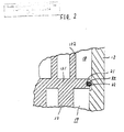
- a sealing structure 20 ( Figure 2) is formed in the outer peripheral wall of circular end plate 131 to insulate suction chamber 18 and discharge chamber 19.
- the sealing structure 20 includes a circumferential groove 21 formed in the outer peripheral surface of circular end plate 131 and an O-ring seal element 22 disposed in the circumferential groove 21.
- Formation of circumferential groove 21 is accomplished by a cutting process, comprising seven steps, shown in Figures 3a through 3g in which circular end plate 131 is mounted for rotation proximate a surface cutting tool.
- a first step shown in Figure 3a, the outer peripheral surface 131a of circular end plate 131 and the outer circumferential portion 131e of the surface of circular end plate 131 are cut by a surface cutting tool 201 which is attached to a numerical controlled lathe (not shown).
- steps 2-4 shown in Figures 3b through 3d, respectively, outer peripheral surface 131a of circular end plate 131 is cut by a groove cutting tool 202.
- groove cutting tool 202 will have a vertical sectional view similar to that of circumferential groove 21, i.e., the groove cutting tool 202 is used as a forming tool.
- the final steps in the process are shown in Figures 3e through 3g, in which the corners of circumferential groove 21 are rounded by groove cutting tool 202.
- a scroll type compressor includes a housing having a fluid inlet port and a fluid outlet port.
- a fixed scroll is fixedly disposed in the housing and has an ond plate from which a first spiral element extends.
- An orbiting scroll is also disposed in the housing and has an end plate from which a second spiral element extends.
- the end plate of the fixed scroll partitions an inner chamber of the housing into a suction chamber and a discharge chamber.
- a driving mechanism is operatively connected to the orbiting scroll and to a drive shaft to effect orbital motion of the orbiting scroll during rotation of the drive shaft. Rotation of the orbiting scroll is prevented by a rotation preventing device.
- the fixed scroll and the orbiting scroll are maintained angularly and radially offset from each other so that the spiral elements interfit to form a plurality of line contacts between their spiral curved surfaces which seal-off and define at least one pair of fluid pockets.
- the orbital movement of the orbiting scroll relative to the fixed scroll shifts the line contacts along the spiral curved surfaces of the spiral elements which changes the volume of the fluid pockets.
- a sealing structure for insulating the suction chamber and the discharge chamber, is formed between the outer peripheral surface of the end plate of the fixed scroll and the inner peripheral wall of the housing.
- the sealing structure includes an annular cut-out portion, having a generally L-shaped sectional side view, formed in the outer peripheral surface of the end plate of the fixed scroll, an annular ridge formed in the inner peripheral wall of the housing and an O-ring seal element disposed between the annular cut-out portion and the annular ridge.
- Compressor 1 includes a compressor housing 10 having a front end plate 11 and a cup shaped casing 12, which is attached to an end surface of front plate 11 to define an inner chamber between the inner wall of casing 12 and the rearwardly facing surface of front end plate 11.
- a fixed scroll 13 Disposed within the inner chamber of cup shaped casing 12 are a fixed scroll 13 having a circular end plate 131 from which a spiral element 132 extends, an orbiting scroll 14 having a circular end plate 141 from which a spiral element 142 extends, a driving mechanism 15 and a rotation preventing/thrust bearing device 16.
- Fixed scroll 13 is fixed to the rear end plate of cup shaped casing 12 by screws 133.
- Scrolls 13 and 14 are maintained angularly and radially offset from each other so that spiral elements 132, 142 interfit to form a plurality of line contacts between their spiral curved surfaces which define at least one pair of sealed off fluid pockets 51.
- the circular end plate 141 of the orbiting scroll 14 is provided with a boss 143 projecting annularly from the surface of end plate 141 opposite the surface from which spiral element 142 extends.
- a drive shaft 151 penetrates an opening 111 of front end plate 11 and is rotatably supported by front end plate 11 through a bearing 17 and a sleeve 171.
- Drive shaft 151 is operatively connected at one end with driving mechanism 15 which includes a disk shaped rotor 152 formed at the inner end of drive shaft 151, a driving pin (not shown) attached to the disk shaped rotor 152 eccentrically, and a bushing 153 connected to the driving pin.
- Bushing 153 is connected to orbiting scroll 14 through a bearing 154 which is disposed on the inner wall of boss 143.
- bushing 153 also tends to rotate eccentrically.
- rotation of orbiting scroll 14 is prevented by rotation preventing/thrust bearing device 16 so that orbiting scroll 14 exhibits orbital motion.
- Circular end plate 131 of fixed scroll 13 partitions the inner chamber of cup shaped casing 12 into a suction chamber 18 and a discharge chamber 19.
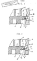
- a sealing structure 30, for insulating suction chamber 18 and discharge chamber 19, is formed between the outer peripheral surface of circular end plate 131 and the inner peripheral wall of cup shaped casing 12.
- sealing structure 30 includes an annular cut-out portion 31, having an L-shaped sectional side view, formed in the outer peripheral surface of circular end plate 131, an annular ridge 32 formed in the inner peripheral wall of cup shaped casing 12 and an O-ring seal element 33 disposed between annular cut-out portion 31 and annular ridge 32.
- annular ridge 32 is accomplished by a cutting process in which cup shaped casing 12 is mounted for rotation proximate a cutting tool, which is attached to a numerical controlled lathe. During rotation of casing 12, the cutting tool is controlled to move in an longitudinal direction along the inner surface of the casing and to cut away a portion of the peripheral surface of the inner wall of the casing. As a result of the cutting operation, the inner wall of at least a portion of discharge chamber 19 is thicker, by "h" in Figure 5, than the inner wall of suction chamber 18 so that annular ridge 82 is formed.
- annular ridge 32 is positioned at a distance from circular end plate 131 so that a gap, having width "t" in Figure 5, is created between the rearwardly facing surface of circular end plate 131 and the surface of annular ridge 32 when fixed scroll 13 is fixedly secured to cup shaped casing 12. This gap prevents circular end plate 131 from contacting annular ridge 82 during operation of the compressor, and thus protects the scroll from damage.
- annular cut-out portion 31 is accomplished by a cutting process in which circular end plate 131 is mounted for rotation proximate a surface cutting tool 201, which is attached to a numerical controlled lathe (not shown).
- a first step shown in Figure 6a, cutting tool 201 is positioned to cut the outer circumferential portion 131e of the opposite surface of circular end plate 131.
- cutting tool 201 is repositioned to cut the outer peripheral surface of circular end plate 131 to thereby form annular cut-out portion 31 and a projection 34, located at the upper portion of the outer peripheral surface of circular end plate 131, as shown in Figure 5.
- cutting tool 201 is repositioned, again as part of a continuous movement, to cut away a corner 35 formed by the lateral surface of annular cut-out portion 31 and the outer peripheral surface of projection 34.
- a sealing structure 30 in accordance with a second embodiment of the present invention is shown.
- the longitudinal surface 31a of annular cut-out portion 31 is slanted, and gradually extends toward the inner wall of casing 12.
- a sealing structure 30 in accordance with a third embodiment of the present invention is shown.
- the lower (relative to Figure 8) part of the longitudinal surface 31b of annular cut-out portion 31 is slanted, and gradually extends toward the inner wall of casing 12.
- sealing structure 30 in accordance with a fourth embodiment of the present invention is shown.
- both annular cut-out portion 31 and annular ridge 32 are located on the suction chamber side of circular end plate 131.
- Sealing structure 30, thus, comprises annular cut-out portion 31 formed at the upper (relative to Figure 9) part of the outer peripheral surface of circular end plate 131, and annular ridge 32 is formed in the inner surface of suction chamber 18.
- annular cut-out portion 31 shown in each of Figures 7 and 8 is formed using the same two-step cutting process described above with respect to Figure 6a and 6b, except that the blade angle of the cutting tool used in the process will be different depending upon the configuration of cut-out portion 31.
Landscapes
- Engineering & Computer Science (AREA)
- Mechanical Engineering (AREA)
- General Engineering & Computer Science (AREA)
- Rotary Pumps (AREA)
- Applications Or Details Of Rotary Compressors (AREA)
Applications Claiming Priority (2)
| Application Number | Priority Date | Filing Date | Title |
|---|---|---|---|
| JP1987050617U JPS63158594U (fr) | 1987-04-04 | 1987-04-04 | |
| JP50617/87U | 1987-04-04 |
Publications (3)
| Publication Number | Publication Date |
|---|---|
| EP0286341A2 true EP0286341A2 (fr) | 1988-10-12 |
| EP0286341A3 EP0286341A3 (en) | 1989-06-14 |
| EP0286341B1 EP0286341B1 (fr) | 1991-11-27 |
Family
ID=12863935
Family Applications (1)
| Application Number | Title | Priority Date | Filing Date |
|---|---|---|---|
| EP88302988A Expired - Lifetime EP0286341B1 (fr) | 1987-04-04 | 1988-04-05 | Compresseur à volute |
Country Status (7)
| Country | Link |
|---|---|
| US (1) | US4913635A (fr) |
| EP (1) | EP0286341B1 (fr) |
| JP (1) | JPS63158594U (fr) |
| KR (1) | KR970006516B1 (fr) |
| AU (1) | AU621044B2 (fr) |
| CA (1) | CA1308403C (fr) |
| DE (1) | DE3866400D1 (fr) |
Families Citing this family (11)
| Publication number | Priority date | Publication date | Assignee | Title |
|---|---|---|---|---|
| JPH039094A (ja) * | 1989-06-02 | 1991-01-16 | Sanden Corp | スクロール型圧縮機 |
| JPH04120527U (ja) * | 1991-04-09 | 1992-10-28 | 三菱重工業株式会社 | 空気調和機 |
| JPH04117195U (ja) * | 1991-04-02 | 1992-10-20 | サンデン株式会社 | スクロール型圧縮機 |
| JPH08159055A (ja) * | 1994-12-08 | 1996-06-18 | Sanden Corp | 高圧タイプ圧縮機 |
| JPH10205467A (ja) * | 1997-01-27 | 1998-08-04 | Sanden Corp | スクロールコンプレッサ |
| JP3473448B2 (ja) * | 1998-10-05 | 2003-12-02 | 松下電器産業株式会社 | 圧縮機およびその組立て方法 |
| KR100404118B1 (ko) * | 2001-08-17 | 2003-11-03 | 엘지전자 주식회사 | 스크롤 압축기의 지그 장치 |
| JP2006291925A (ja) * | 2005-04-14 | 2006-10-26 | Sanden Corp | スクロール型流体機械 |
| US7841845B2 (en) * | 2005-05-16 | 2010-11-30 | Emerson Climate Technologies, Inc. | Open drive scroll machine |
| US8147230B2 (en) * | 2009-04-06 | 2012-04-03 | Chu Henry C | Scroll compressor having rearwardly directed fluid inlet and outlet |
| JP6074203B2 (ja) * | 2012-09-25 | 2017-02-01 | 株式会社ヴァレオジャパン | スクロール型圧縮機 |
Family Cites Families (14)
| Publication number | Priority date | Publication date | Assignee | Title |
|---|---|---|---|---|
| US2728300A (en) * | 1951-08-27 | 1955-12-27 | Aero Supply Mfg Co Inc | Gear pump |
| US2922376A (en) * | 1956-09-07 | 1960-01-26 | Tokheim Corp | Variable capacity pump |
| US3132869A (en) * | 1961-03-13 | 1964-05-12 | Malcolm R Maben | Fluid pressure responsive seal assembly |
| CH470609A (de) * | 1967-12-06 | 1969-03-31 | Kistler Instrumente Ag | Dichtungsanordnung |
| US3490383A (en) * | 1969-01-29 | 1970-01-20 | Koehring Co | Hydraulic pump or motor |
| US3695790A (en) * | 1971-05-24 | 1972-10-03 | Charles Jones | Housing sealing means for rotary engines |
| AU5375079A (en) * | 1978-12-15 | 1980-07-10 | Sankyo Electric Co. Ltd. | Scroll type compressor |
| CH640607A5 (en) * | 1979-08-29 | 1984-01-13 | Sig Schweiz Industrieges | Screw pump |
| JPS5716292A (en) * | 1980-07-01 | 1982-01-27 | Sanden Corp | Scroll type compressor |
| JPS5958791U (ja) * | 1982-10-09 | 1984-04-17 | サンデン株式会社 | スクロ−ル圧縮機 |
| JPS59142485U (ja) * | 1983-03-15 | 1984-09-22 | サンデン株式会社 | スクロ−ル型圧縮機 |
| EP0326189B1 (fr) * | 1985-08-10 | 1991-12-11 | Sanden Corporation | Compresseur à volutes imbriquées avec mécanisme de réglage du déplacement |
| JPH0746787Y2 (ja) * | 1987-12-08 | 1995-10-25 | サンデン株式会社 | 可変容量型スクロール圧縮機 |
| US4784240A (en) * | 1988-03-16 | 1988-11-15 | Westinghouse Electric Corp. | Method for using door cycle time in dispatching elevator cars |
-
1987
- 1987-04-04 JP JP1987050617U patent/JPS63158594U/ja active Pending
-
1988
- 1988-04-04 KR KR1019880003769A patent/KR970006516B1/ko not_active Expired - Lifetime
- 1988-04-04 US US07/177,117 patent/US4913635A/en not_active Expired - Lifetime
- 1988-04-05 DE DE8888302988T patent/DE3866400D1/de not_active Expired - Lifetime
- 1988-04-05 AU AU14147/88A patent/AU621044B2/en not_active Expired
- 1988-04-05 EP EP88302988A patent/EP0286341B1/fr not_active Expired - Lifetime
- 1988-04-05 CA CA000563279A patent/CA1308403C/fr not_active Expired - Lifetime
Also Published As
| Publication number | Publication date |
|---|---|
| CA1308403C (fr) | 1992-10-06 |
| DE3866400D1 (de) | 1992-01-09 |
| AU1414788A (en) | 1988-10-06 |
| KR880012893A (ko) | 1988-11-29 |
| AU621044B2 (en) | 1992-03-05 |
| EP0286341B1 (fr) | 1991-11-27 |
| US4913635A (en) | 1990-04-03 |
| KR970006516B1 (ko) | 1997-04-28 |
| EP0286341A3 (en) | 1989-06-14 |
| JPS63158594U (fr) | 1988-10-18 |
Similar Documents
| Publication | Publication Date | Title |
|---|---|---|
| EP1122437B1 (fr) | Compresseur à spirales | |
| EP0227249B1 (fr) | Mécanisme d'étanchéité axiale pour appareil à déplacement de fluide du type à volute | |
| EP0286341A2 (fr) | Compresseur à volute | |
| US4645436A (en) | Scroll type fluid displacement apparatus with improved anti-wear device | |
| US5779461A (en) | Scroll type fluid displacement apparatus having a control system of line contacts between spiral elements | |
| US4808094A (en) | Drive system for the orbiting scroll of a scroll type fluid compressor | |
| JPH07324689A (ja) | スクロール型流体機械 | |
| JPS5968583A (ja) | スクロ−ル型流体装置 | |
| CN113614377A (zh) | 涡旋式压缩机 | |
| CA2019295C (fr) | Appareil de deplacement d'un fluide a aubages spiraux | |
| JP4979473B2 (ja) | スクロール圧縮機 | |
| AU615361B2 (en) | Scroll member for scroll type fluid displacement apparatus | |
| JP2009024664A (ja) | スクロール型流体機械 | |
| US4956058A (en) | Scroll type fluid displacement apparatus with surface treated spiral element | |
| JP2743990B2 (ja) | スクロール型圧縮装置 | |
| EP0172674B1 (fr) | Compresseur à fluide du type à spirales imbriquées | |
| EP0797003A1 (fr) | Dispositif d'accouplement du type Oldham pour appareil de déplacement de fluides à spirales | |
| US5848883A (en) | Scroll compressor having a back pressure partitioning member | |
| JP2934556B2 (ja) | スクロール型流体機械 | |
| US6471499B1 (en) | Scroll compressor with lubrication directed to drive flat surfaces | |
| EP0468238B1 (fr) | Compresseur à spirales avec mécanisme de déplacement variable | |
| JP2001055989A (ja) | スクロール型圧縮機 | |
| JPS59180094A (ja) | スクロ−ル型圧縮装置 | |
| JP3377907B2 (ja) | 流体機械 | |
| JP3219497B2 (ja) | スクロール型流体機械 |
Legal Events
| Date | Code | Title | Description |
|---|---|---|---|
| PUAI | Public reference made under article 153(3) epc to a published international application that has entered the european phase |
Free format text: ORIGINAL CODE: 0009012 |
|
| AK | Designated contracting states |
Kind code of ref document: A2 Designated state(s): DE FR GB IT SE |
|
| PUAL | Search report despatched |
Free format text: ORIGINAL CODE: 0009013 |
|
| AK | Designated contracting states |
Kind code of ref document: A3 Designated state(s): DE FR GB IT SE |
|
| 17P | Request for examination filed |
Effective date: 19891127 |
|
| 17Q | First examination report despatched |
Effective date: 19900806 |
|
| GRAA | (expected) grant |
Free format text: ORIGINAL CODE: 0009210 |
|
| AK | Designated contracting states |
Kind code of ref document: B1 Designated state(s): DE FR GB IT SE |
|
| ET | Fr: translation filed | ||
| REF | Corresponds to: |
Ref document number: 3866400 Country of ref document: DE Date of ref document: 19920109 |
|
| ITF | It: translation for a ep patent filed | ||
| PLBE | No opposition filed within time limit |
Free format text: ORIGINAL CODE: 0009261 |
|
| STAA | Information on the status of an ep patent application or granted ep patent |
Free format text: STATUS: NO OPPOSITION FILED WITHIN TIME LIMIT |
|
| 26N | No opposition filed | ||
| EAL | Se: european patent in force in sweden |
Ref document number: 88302988.6 |
|
| REG | Reference to a national code |
Ref country code: GB Ref legal event code: IF02 |
|
| PGFP | Annual fee paid to national office [announced via postgrant information from national office to epo] |
Ref country code: DE Payment date: 20070329 Year of fee payment: 20 |
|
| PGFP | Annual fee paid to national office [announced via postgrant information from national office to epo] |
Ref country code: SE Payment date: 20070404 Year of fee payment: 20 |
|
| PGFP | Annual fee paid to national office [announced via postgrant information from national office to epo] |
Ref country code: GB Payment date: 20070404 Year of fee payment: 20 |
|
| PGFP | Annual fee paid to national office [announced via postgrant information from national office to epo] |
Ref country code: IT Payment date: 20070625 Year of fee payment: 20 |
|
| PGFP | Annual fee paid to national office [announced via postgrant information from national office to epo] |
Ref country code: FR Payment date: 20070411 Year of fee payment: 20 |
|
| REG | Reference to a national code |
Ref country code: GB Ref legal event code: PE20 Expiry date: 20080404 |
|
| EUG | Se: european patent has lapsed | ||
| PG25 | Lapsed in a contracting state [announced via postgrant information from national office to epo] |
Ref country code: GB Free format text: LAPSE BECAUSE OF EXPIRATION OF PROTECTION Effective date: 20080404 |