EP0286353A1 - Fülldüse für unter Druck stehenden Kraftstoff - Google Patents
Fülldüse für unter Druck stehenden Kraftstoff Download PDFInfo
- Publication number
- EP0286353A1 EP0286353A1 EP88303014A EP88303014A EP0286353A1 EP 0286353 A1 EP0286353 A1 EP 0286353A1 EP 88303014 A EP88303014 A EP 88303014A EP 88303014 A EP88303014 A EP 88303014A EP 0286353 A1 EP0286353 A1 EP 0286353A1
- Authority
- EP
- European Patent Office
- Prior art keywords
- valve
- connection
- sleeve
- cam
- passage
- Prior art date
- Legal status (The legal status is an assumption and is not a legal conclusion. Google has not performed a legal analysis and makes no representation as to the accuracy of the status listed.)
- Granted
Links
Images


Classifications
-
- B—PERFORMING OPERATIONS; TRANSPORTING
- B67—OPENING, CLOSING OR CLEANING BOTTLES, JARS OR SIMILAR CONTAINERS; LIQUID HANDLING
- B67D—DISPENSING, DELIVERING OR TRANSFERRING LIQUIDS, NOT OTHERWISE PROVIDED FOR
- B67D7/00—Apparatus or devices for transferring liquids from bulk storage containers or reservoirs into vehicles or into portable containers, e.g. for retail sale purposes
- B67D7/06—Details or accessories
- B67D7/42—Filling nozzles
-
- B—PERFORMING OPERATIONS; TRANSPORTING
- B64—AIRCRAFT; AVIATION; COSMONAUTICS
- B64F—GROUND OR AIRCRAFT-CARRIER-DECK INSTALLATIONS SPECIALLY ADAPTED FOR USE IN CONNECTION WITH AIRCRAFT; DESIGNING, MANUFACTURING, ASSEMBLING, CLEANING, MAINTAINING OR REPAIRING AIRCRAFT, NOT OTHERWISE PROVIDED FOR; HANDLING, TRANSPORTING, TESTING OR INSPECTING AIRCRAFT COMPONENTS, NOT OTHERWISE PROVIDED FOR
- B64F1/00—Ground or aircraft-carrier-deck installations
- B64F1/28—Liquid-handling installations specially adapted for fuelling stationary aircraft
-
- Y—GENERAL TAGGING OF NEW TECHNOLOGICAL DEVELOPMENTS; GENERAL TAGGING OF CROSS-SECTIONAL TECHNOLOGIES SPANNING OVER SEVERAL SECTIONS OF THE IPC; TECHNICAL SUBJECTS COVERED BY FORMER USPC CROSS-REFERENCE ART COLLECTIONS [XRACs] AND DIGESTS
- Y10—TECHNICAL SUBJECTS COVERED BY FORMER USPC
- Y10T—TECHNICAL SUBJECTS COVERED BY FORMER US CLASSIFICATION
- Y10T137/00—Fluid handling
- Y10T137/6851—With casing, support, protector or static constructional installations
- Y10T137/6855—Vehicle
- Y10T137/6881—Automotive
-
- Y—GENERAL TAGGING OF NEW TECHNOLOGICAL DEVELOPMENTS; GENERAL TAGGING OF CROSS-SECTIONAL TECHNOLOGIES SPANNING OVER SEVERAL SECTIONS OF THE IPC; TECHNICAL SUBJECTS COVERED BY FORMER USPC CROSS-REFERENCE ART COLLECTIONS [XRACs] AND DIGESTS
- Y10—TECHNICAL SUBJECTS COVERED BY FORMER USPC
- Y10T—TECHNICAL SUBJECTS COVERED BY FORMER US CLASSIFICATION
- Y10T137/00—Fluid handling
- Y10T137/8593—Systems
- Y10T137/87917—Flow path with serial valves and/or closures
- Y10T137/88054—Direct response normally closed valve limits direction of flow
Definitions
- the refueling of commercial airplanes is accomplished through pressurized fuel systems.
- the tank inlet on the airplane is usually located under the wing, and a nozzle mounted on the end of a supply hose is attached to the tank inlet and includes a valve which displaces the tank inlet valve as the nozzle valve is opened to permit the flow of fuel through the nozzle and through the tank inlet.
- Such aircraft refueling nozzles must include safety devices to prevent fuel spillage, and be as foolproof and trouble-free as possible.
- Another object of the invention is to provide a pressurized fuel nozzle having an extendable and retractable valve wherein the operation of the valve is positive and trouble-free and wherein the operator may readily discern the valve position during all conditions of operation.
- a further object of the invention is to provide a fuel nozzle for a pressurized fuel system having a retractable and extendable valve wherein the valve operator is rendered inoperative until the nozzle is fully connected and locked to the tank inlet.
- Yet another object of the invention is to provide a fuel nozzle for pressurized fuel systems wherein a rotatable connection sleeve is mounted on the nozzle body rotatable between nozzle connecting and disconnecting positions, and the nozzle includes an interlock sensing the placing of the nozzle on the tank inlet and rotation of the connection sleeve to the locked condition cannot occur until the nozzle is properly aligned, oriented and located upon the tank inlet.
- An additional object of the invention is to provide a fuel nozzle for a pressurized fuel system having an extendable and retractable valve positionable between open and closed conditions wherein an interlock prevents the nozzle from being disconnected from the tank inlet until the nozzle valve has been closed.
- the fuel nozzle is adapted to be attached to a standard aircraft tank inlet.
- a standard aircraft tank inlet includes a self-sealing valve and lugs which cooperate with a bayonet-type connection on the nozzle permitting the fueling nozzle to be attached to the inlet.
- the nozzle includes an annular body having a flow passage defined therein and a connection end for mounting upon the tank inlet.
- a connection sleeve concentrically rotatably mounted upon the nozzle body includes a bayonet connection for cooperating with the inlet lugs and placing of the nozzle end upon the tank inlet and rotation of the connection sleeve will lock the nozzle body to the tank inlet.
- a sensing ring concentrically mounted upon the nozzle engages the tank inlet and is axially displaced relative to the nozzle body upon the nozzle being aligned with the tank inlet and axially inserted thereon. Displacing of the sensing ring permits rotation of the connection sleeve on the body and insures that the nozzle is fully connected to the tank inlet prior to the nozzle valve being opened.
- the nozzle passage includes an axially displaceable annular valve which closes the nozzle body passage to fluid flow in a retracted position, and permits fluid flow through the nozzle when the valve is extended.
- a rotatable valve actuator on the body includes a cam cooperating with a cam follower affixed to the valve wherein rotation of the cam actuator, which is in the form of an annular cam sleeve, axially displaces the valve relative to the body. Extension of the nozzle valve automatically displaces the tank inlet valve to an open condition permitting fluid flow through the nozzle into the tank.
- connection sleeve also receives the cam follower and the configuration of the interlock slot on the connection sleeve prevents operation of the valve cam sleeve until the connection sleeve has been rotated on the body to the nozzle fully connected position.
- the interlocks defined on the nozzle body prevent the nozzle valve from being opened until the nozzle is fully connected to the tank inlet, and the nozzle cannot be removed from the tank inlet until the nozzle valve has been closed.
- the nozzle valve is of a hollow annular configuration free of internal actuating structure or components, and the connection sleeve and the valve cam sleeve are concentrically related to the valve body axis permitting the valve to be of a concise configuration, easily operable and handled, and economically manufacturable.
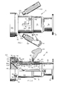
- a fueling nozzle 10 in accord with the invention includes a generally cylindrical body 12 of tubular configuration having a flow passage 14 defined therein of cylindrical form including a longitudinal axis.
- the body includes an extension 16, which may be linear or annular, defining the nozzle inlet end, and a flange 18 formed upon the extension includes holes whereby the flange may be attached to a flexible fuel supply hose, not shown, as conventionally known.
- the opposite end of the body 12 is designated the outlet end 20 and the nozzle passage intersects each end of the body.
- valve sleeve 22 Internally, the body encloses a cylindrical tubular valve sleeve 22 sealed within the passage 14 by O-rings, and the configuration of the valve sleeve is best appreciated form Fig. 4.
- the valve sleeve includes an internal cylindrical bore having O-ring receiving grooves defined therein for sealing the valve therein as later described, and externally, the valve sleeve includes an annular shoulder 24 having a pair of diametrically located recesses for receiving the spring biased continuity balls 26, Fig. 2.
- the valve sleeve includes a cylindrical surface 28, a cylindrical surface 30 and a linear slot 32 defined in cylindrical surface 34 which is parallel to the valve sleeve axis, which is coincident with the body passage axis.
- a cam sleeve 36 is rotatably mounted upon the valve sleeve surface 34.
- the cam sleeve includes an end which engages the valve sleeve shoulder 24 and an annular flange 38 is homogeneously defined on the other end of the cam sleeve extending radially from the general configuration thereof and includes threaded holes 40, Fig. 5, for receiving bolts 42 whereby the cam sleeve operating handle 44 may be affixed to the cam sleeve for rotation thereof.
- the cam sleeve includes a cam slot 46 defined through the wall of the cam sleeve cylindrical portion 48, and the cam slot includes the transverse portion 50, the intermediate portions 52 and 54 and the transverse portion 56 which includes the enlarged cavity 58.
- valve sleeve 22 and cam sleeve 36 are maintained within the body passage 14 by means of rings 60 and 62, Fig. 2, and the ring 62 is affixed to the body by a drive wire 64 received within opposed grooves defined in the body 12 and the ring 62.
- a snap ring 66 received within a groove defined in the valve sleeve axially aligns with the ring 60, and as the rings 60 and 62 are also in axial alignment with the cam sleeve, axial location of the valve and cam sleeves within the passage 14 is achieved.
- connection sleeve 68 is rotatably mounted upon the valve sleeve 22 and the cam sleeve 36 and includes an inner end disposed adjacent the cam sleeve flange 38, and the outer end of the connection sleeve includes annular shoulder 70 over which the neoprene bumper 72 is located and encompasses.
- the bumper 72 prevents impact damage from occurring at the outlet end 20 of the body.
- the annular lug adapter 74 is attached to the connection sleeve shoulder 70 by three screws extending through holes 76, Fig. 6, and the lug adapter includes three bayonet connection notches 78, Fig. 6, each in communication with the arcuate cam recesses 80 for cooperation with the tank inlet adapter, as known.
- the bumper 72 circumferentially encompasses the lug adapter 74 for the protection thereof.
- a sensing ring 82 is mounted upon the valve sleeve surface 28 for axial displacement thereon.
- the sensing ring includes several axially extending projections 84 which cooperate with notches defined in the fuel inlet adapter, and the ring also includes a pair of slots 86, diametrically located, each of which includes a portion 88 parallel to the length of the ring circumference and a transverse portion 90 at right angles to the portion 88.
- the sensing ring 82 also includes a pair of slots 92, Fig. 2, which extend transversely with respect to the ring circumference, and each of these slots, diametrically located, receive a pin 94 extending from the valve sleeve holes 96 which function as keys to prevent relative rotation between the valve sleeve 22 and the sensing ring 82.
- connection sleeve 68 includes a pair of interlock pins 98 threaded into the shoulder 70 having a reduced diameter portion extending into the sensing ring slots 86.
- Compression spring 100 located between the sensing ring 82 and the valve sleeve shoulder 24 imposes a biasing force on the sensing ring toward the body outlet end 20.
- connection sleeve 68 Rotation of the connection sleeve 68 is accomplished through a pair of handles 102 threaded into bosses 104 homogeneously extending from the connection sleeve.
- the handles are large and of such dimension as to be easily grasped by the operator whereby the operator will use the handles to lift and position the nozzle 10 and associated hose.
- the connection sleeve also includes an interlock slot 106 having an axial portion 108 and parallel to the passage 14 and a transverse portion 110.
- the nozzle valve is of a cylindrical tubular configuration and is reciprocally received within the valve sleeve 22.
- the valve 112 includes an axial flow passage portion 114 open at its right end, Fig. 2, in communication with the body passage 14, and at its left end the portion 114 communicates with oblique ports 116 intersecting the exterior of the valve adjacent the head 118.
- the head 118 includes a cylindrical surface cooperating with seal 120 formed in the valve sleeve whereby the outlet end of the body passage 14 is sealed when the valve 112 is in the retracted position shown in Fig. 2.
- the outlet end thereof may be protected by a dust cap 122 which is snapped onto the bumper 72 and protects the outlet end 20 of the nozzle from contamination by foreign matter.
- the aforedescribed fueling nozzle is attached to a conventional tank inlet 124 as represented in Fig. 3.
- the tank inlet is defined in the bulkhead 126, and includes an adapter 128 affixed to the bulkhead having three axially extending lugs 130 each formed with a radially extending head 132.
- the tank inlet valve 134 is held in position by the spider 136, and a compression spring 138 biases the valve 134 into a sealed relationship with the inlet adapter 128, and displacement of the valve from the adapter permits fuel to flow into the tank generally indicated at 140, as described below.
- a cam follower 142 is affixed to the valve 112 mounted within enlarged portion 144 and the cam follower extends through the valve sleeve slot 32, the cam sleeve slot 46, and the connection sleeve slot 106.
- a bushing 146 is located upon the cam follower for close sliding reception within the valve sleeve slot 32, cam follower bushing 148 is received within cam sleeve slot 46, and bushing 150 is received within connection sleeve slot 106.
- connection sleeve slot portion 110 functions as an interlock to prevent extension of the valve 112 as would permit flow from the nozzle.
- the dust cap 122 is removed and the nozzle body 12 is aligned with the tank inlet adapter 128.
- the heads 132 of the lugs 130 are received within the lug adapter notches 78 and the nozzle body may be axially pushed onto the tank adapter. This relative axial movement between the nozzle body and tank adapter produces engagement of the lug heads 132 with the sensing ring 82, and simultaneously the sensing ring projections 84 enter notches 152 defined in the tank adapter 128.
- the reception of the sensing ring projections within the adapter notches 152 prevents relative rotation between the nozzle body 12 and the tank adapter 128, and the axial displacement of the sensing ring 82 relative to the valve sleeve 22 shifts the pins 98 from engagement with the sensing ring slot portion 90 and aligns the pins with the slot portion 88.
- the alignment of the pins 98 with the slot portions 88 now permits the operator to rotate the connection sleeve 68 clockwise relative to the body 12 and such relative motion was previously prevented due to the reception of the pins 98 within the sensing ring slot portions 90.
- connection sleeve 68 through handles 102 also rotates the lug adapter 74 relative to the lugs 130 misaligning the heads 132 with respect to the notches 78 wherein the heads 132 engage the oblique cam surfaces within recesses 80 to firmly attach the body 12 in sealed relationship to the tank adapter 128 by means of nozzle seals 154.
- connection sleeve 68 upon the body 12 produces a relative movement between the connection sleeve and the cam follower 142.
- Such locking rotation of the connection sleeve will now position the cam follower 142 in the dotted line position shown in Fig. 7 in axial alignment with the connection sleeve slot portion 108.
- Such alignment now permits rotation of the cam sleeve 36 by rotation through operation of the handle 44.
- the cam sleeve moves in a clockwise direction, the cam sleeve oblique slot portions 52 and 54 will displace the cam follower 142 toward the body outlet end 20 as shown in Fig. 8, and this displacing of the cam follower axially translates the valve 112 to the left, Fig.
- the nozzle 10 cannot be inadvertently removed from the tank adapter 128.
- the reception of the sensing ring projections 84 within the tank adapter notches 152 prevents relative rotation of the nozzle to the tank adapter, and accidental uncoupling of the nozzle from the tank adapter while the valve 112 is open and fuel is flowing through the nozzle cannot take place.
- the operator To disconnect the nozzle 10 from the tank adapter 128 the operator must, first, close the valve 112 by retracting the valve into the body 12. This operation is accomplished by rotating the cam sleeve 36 by means of its handle 44 in a counterclockwise direction causing the cam sleeve cam portions 54 and 52 to displace the cam follower 142 to the right, reversing the sequence of operation described above. Movement of the cam follower to the right retracts the valve 112 into the body 12 to the fully closed position shown in Fig. 2, and in such condition the cam follower will be located at the dotted line position shown in Fig. 7, i.e. in alignment with the connection sleeve slot portion 110.
- connection sleeve 68 on the body 12 by means of handles 102, and this rotation permits alignment of the tank lug heads 132 with the nozzle adapter notches 78.
- rotation of the connection sleeve also aligns the pins 98 with the sensing ring slot portion 90, and as the nozzle is removed from the tank inlet the spring 100 biases the sensing ring outwardly locating the pins 98 within the sensing ring slot portion 90 as shown in Fig. 10.
- the disconnecting operation is now completed, the valve 112 has been fully closed and no leakage occurs.
- the tank valve 134 closes and only minute quantities of fuel are spilled during disconnection.
- the dust cap 122 may be displaced, and the nozzle is now ready for its next use.
- a fuel nozzle in accord with the invention utilizes a foolproof interlock system which prevents the nozzle from being opened unless the nozzle is fully connected to a tank inlet, and likewise, the nozzle interlocks prevent the nozzle from being removed from the tank inlet unless the nozzle valve is fully closed.
- the valve 112 is open throughout its length providing substantially unrestricted fluid flow therethrough and little pressure loss is experienced. Additionally, as the interior of the valve is free of actuating apparatus, the possibility of broken parts within the nozzle entering the fuel tank is substantially completely eliminated.
- the concentric relationship of the valve, valve sleeve, cam sleeve and connection sleeve permits the valve to be of a relatively concise configuration, and the nozzle components are of such shape as to be readily manufacturable on conventional machine equipment.
Landscapes
- Engineering & Computer Science (AREA)
- Mechanical Engineering (AREA)
- Aviation & Aerospace Engineering (AREA)
- Cooling, Air Intake And Gas Exhaust, And Fuel Tank Arrangements In Propulsion Units (AREA)
- Loading And Unloading Of Fuel Tanks Or Ships (AREA)
Applications Claiming Priority (2)
| Application Number | Priority Date | Filing Date | Title |
|---|---|---|---|
| US07/036,895 US4794960A (en) | 1987-04-09 | 1987-04-09 | Pressure fuel nozzle |
| US36895 | 1987-04-09 |
Publications (2)
| Publication Number | Publication Date |
|---|---|
| EP0286353A1 true EP0286353A1 (de) | 1988-10-12 |
| EP0286353B1 EP0286353B1 (de) | 1991-10-23 |
Family
ID=21891265
Family Applications (1)
| Application Number | Title | Priority Date | Filing Date |
|---|---|---|---|
| EP88303014A Expired - Lifetime EP0286353B1 (de) | 1987-04-09 | 1988-04-05 | Fülldüse für unter Druck stehenden Kraftstoff |
Country Status (4)
| Country | Link |
|---|---|
| US (1) | US4794960A (de) |
| EP (1) | EP0286353B1 (de) |
| CA (1) | CA1301722C (de) |
| DE (1) | DE3865720D1 (de) |
Cited By (4)
| Publication number | Priority date | Publication date | Assignee | Title |
|---|---|---|---|---|
| WO1995002554A1 (en) * | 1993-07-16 | 1995-01-26 | Gogas (Australia) Pty. Ltd. | Fluid dispensing nozzle |
| EP1346946A1 (de) * | 2002-03-19 | 2003-09-24 | Stäubli Faverges | Zapfpistole mit einer sicheren Arbeitsweise und Betankungsanlage mit einer derartigen Zapfpistole |
| EP3246618A1 (de) * | 2016-05-18 | 2017-11-22 | Transportes Ham | Lng-düsen-sicherheitseinrastmechanismus |
| WO2021052975A1 (de) * | 2019-09-18 | 2021-03-25 | Elaflex Hiby Gmbh & Co. Kg | Zapfventil mit arretierbarem steuerhebel |
Families Citing this family (8)
| Publication number | Priority date | Publication date | Assignee | Title |
|---|---|---|---|---|
| US5172740A (en) * | 1988-06-27 | 1992-12-22 | Simmel Thomas L | Liquid flow control system |
| US5259423A (en) * | 1988-06-27 | 1993-11-09 | Link Research & Development, Inc. | Liquid flow control system |
| US6234224B1 (en) | 2000-03-14 | 2001-05-22 | Robert L. Schultz, Jr. | Aircraft fueling nozzle |
| US6761192B2 (en) | 2002-09-19 | 2004-07-13 | Swiftflo, Llc | Assembly for automatic vehicle fueling |
| DE202005008155U1 (de) * | 2005-05-21 | 2006-07-13 | Weh, Erwin | Betätigungsvorrichtung für eine Schnellanschlusskupplung |
| US7588060B2 (en) * | 2005-09-21 | 2009-09-15 | Flomax International, Inc. | Apparatus, system, and means for a modular backpressure sensor |
| US9938022B2 (en) * | 2014-06-10 | 2018-04-10 | Gammon Technical Products, Inc. | Fueling nozzle adapter |
| PT3767153T (pt) * | 2019-07-16 | 2021-12-02 | Oasis Eng Ltd | Bocal de abastecimento para combustível gasoso ou liquefeito com retardamento entre acoplamento e ativação |
Citations (3)
| Publication number | Priority date | Publication date | Assignee | Title |
|---|---|---|---|---|
| US2716999A (en) * | 1950-05-01 | 1955-09-06 | Parker Appliance Co | Nozzle and associated devices for fueling and defueling tanks |
| EP0117702A2 (de) * | 1983-02-25 | 1984-09-05 | Albert W. Brown | Tankstutzensystem für Flügelunterseite eines Flugzeugs |
| GB2177382A (en) * | 1985-07-08 | 1987-01-21 | Aeroquip Ag | Closed circuit refueling nozzle |
Family Cites Families (11)
| Publication number | Priority date | Publication date | Assignee | Title |
|---|---|---|---|---|
| US2680030A (en) * | 1949-05-27 | 1954-06-01 | Milwaukee Valve Co | Nozzle |
| US2665925A (en) * | 1949-08-02 | 1954-01-12 | Avery Hardoll Ltd | Coupling device for pipes or conduits |
| US2665926A (en) * | 1951-03-06 | 1954-01-12 | Avery Hardoll Ltd | Coupling device for pipes or conduits |
| US2737401A (en) * | 1953-01-26 | 1956-03-06 | Buckeye Iron & Brass Works | Fuel servicing nozzle |
| US2753884A (en) * | 1953-01-26 | 1956-07-10 | Buckeye Iron & Brass Works | Fuel filling adapter |
| US3086565A (en) * | 1959-05-14 | 1963-04-23 | Schulz Tool & Mfg Co | Servicing nozzle |
| US3055405A (en) * | 1959-06-23 | 1962-09-25 | Houston Company | Automatic tank-filling systems |
| US3045721A (en) * | 1960-02-04 | 1962-07-24 | Dover Corp | Under-wing fueling nozzle |
| US3168125A (en) * | 1962-10-03 | 1965-02-02 | Buckeye Iron & Brass Works | Lever operated nozzle |
| US3330313A (en) * | 1965-02-25 | 1967-07-11 | Emco Wheaton | Supply and receiver coupler |
| US3441055A (en) * | 1966-07-05 | 1969-04-29 | Phillip R Pickell | Hydrant and cooperative coupler valve |
-
1987
- 1987-04-09 US US07/036,895 patent/US4794960A/en not_active Expired - Fee Related
-
1988
- 1988-04-05 EP EP88303014A patent/EP0286353B1/de not_active Expired - Lifetime
- 1988-04-05 DE DE8888303014T patent/DE3865720D1/de not_active Expired - Fee Related
- 1988-04-06 CA CA000563396A patent/CA1301722C/en not_active Expired - Lifetime
Patent Citations (3)
| Publication number | Priority date | Publication date | Assignee | Title |
|---|---|---|---|---|
| US2716999A (en) * | 1950-05-01 | 1955-09-06 | Parker Appliance Co | Nozzle and associated devices for fueling and defueling tanks |
| EP0117702A2 (de) * | 1983-02-25 | 1984-09-05 | Albert W. Brown | Tankstutzensystem für Flügelunterseite eines Flugzeugs |
| GB2177382A (en) * | 1985-07-08 | 1987-01-21 | Aeroquip Ag | Closed circuit refueling nozzle |
Cited By (7)
| Publication number | Priority date | Publication date | Assignee | Title |
|---|---|---|---|---|
| WO1995002554A1 (en) * | 1993-07-16 | 1995-01-26 | Gogas (Australia) Pty. Ltd. | Fluid dispensing nozzle |
| EP1346946A1 (de) * | 2002-03-19 | 2003-09-24 | Stäubli Faverges | Zapfpistole mit einer sicheren Arbeitsweise und Betankungsanlage mit einer derartigen Zapfpistole |
| FR2837487A1 (fr) * | 2002-03-19 | 2003-09-26 | Staubli Sa Ets | Pistolet a fonctionnement securise et installation de remplissage comprenant un tel pistolet |
| US7040358B2 (en) | 2002-03-19 | 2006-05-09 | Staubli Faverges | Nozzle with safe functioning and filling installation incorporating such a nozzle |
| EP3246618A1 (de) * | 2016-05-18 | 2017-11-22 | Transportes Ham | Lng-düsen-sicherheitseinrastmechanismus |
| WO2021052975A1 (de) * | 2019-09-18 | 2021-03-25 | Elaflex Hiby Gmbh & Co. Kg | Zapfventil mit arretierbarem steuerhebel |
| US11511988B2 (en) | 2019-09-18 | 2022-11-29 | Elaflex Hiby Gmbh & Co. Kg | Nozzle having a lockable control lever |
Also Published As
| Publication number | Publication date |
|---|---|
| CA1301722C (en) | 1992-05-26 |
| DE3865720D1 (de) | 1991-11-28 |
| EP0286353B1 (de) | 1991-10-23 |
| US4794960A (en) | 1989-01-03 |
Similar Documents
| Publication | Publication Date | Title |
|---|---|---|
| US4794960A (en) | Pressure fuel nozzle | |
| US4567924A (en) | Aircraft under-wing fueling nozzle system | |
| US4438779A (en) | Ball valve coupling | |
| USRE34781E (en) | Coupling adapter | |
| US3077330A (en) | Fluid conduit coupling | |
| US4007909A (en) | Full flow valved fitting | |
| EP0340879B1 (de) | Druckdichte Steckkupplung | |
| US5332001A (en) | Sexless ball valve coupling | |
| US5603353A (en) | Quick disconnect coupling | |
| US4540021A (en) | Balanced valve coupling | |
| EP0330318B1 (de) | Automatisch abschaltender und selbstsperrender Auftankstutzen | |
| EP0928741B1 (de) | Vorrichtung zur Treibstoffaufnahme während des Fluges eines Flugzeuges mit einziehbarer Sonde | |
| US5069260A (en) | Fuel dispensing nozzle with vapor-proof seal | |
| US4638842A (en) | Closed circuit refueling nozzle | |
| US6405768B1 (en) | Pressure fuel servicing nozzle | |
| US4776614A (en) | Coupling with lock indicator | |
| CA1052410A (en) | Coupler with automatic shut-off | |
| US3330313A (en) | Supply and receiver coupler | |
| CA2137825A1 (en) | Coupling device | |
| US3863688A (en) | Convertor for top loading tanks | |
| US5129621A (en) | Dry break coupling | |
| US3086565A (en) | Servicing nozzle | |
| CN113631848A (zh) | 快速连接流体连接器、转环及其组合件 | |
| US3472482A (en) | Fueling nozzle | |
| EP2326863B1 (de) | Flugzeugbetankungshydrantenkupplung mit innenstellringverriegelung |
Legal Events
| Date | Code | Title | Description |
|---|---|---|---|
| PUAI | Public reference made under article 153(3) epc to a published international application that has entered the european phase |
Free format text: ORIGINAL CODE: 0009012 |
|
| 17P | Request for examination filed |
Effective date: 19880820 |
|
| AK | Designated contracting states |
Kind code of ref document: A1 Designated state(s): DE GB |
|
| 17Q | First examination report despatched |
Effective date: 19900522 |
|
| GRAA | (expected) grant |
Free format text: ORIGINAL CODE: 0009210 |
|
| AK | Designated contracting states |
Kind code of ref document: B1 Designated state(s): DE GB |
|
| REF | Corresponds to: |
Ref document number: 3865720 Country of ref document: DE Date of ref document: 19911128 |
|
| PLBE | No opposition filed within time limit |
Free format text: ORIGINAL CODE: 0009261 |
|
| STAA | Information on the status of an ep patent application or granted ep patent |
Free format text: STATUS: NO OPPOSITION FILED WITHIN TIME LIMIT |
|
| 26N | No opposition filed | ||
| PGFP | Annual fee paid to national office [announced via postgrant information from national office to epo] |
Ref country code: DE Payment date: 19930317 Year of fee payment: 6 |
|
| PGFP | Annual fee paid to national office [announced via postgrant information from national office to epo] |
Ref country code: GB Payment date: 19930325 Year of fee payment: 6 |
|
| PG25 | Lapsed in a contracting state [announced via postgrant information from national office to epo] |
Ref country code: GB Effective date: 19940405 |
|
| GBPC | Gb: european patent ceased through non-payment of renewal fee |
Effective date: 19940405 |
|
| PG25 | Lapsed in a contracting state [announced via postgrant information from national office to epo] |
Ref country code: DE Effective date: 19950103 |