EP0286437B1 - Gerät und Verfahren zur Aufzeichnung und Wiedergabe eines digitalen Signals - Google Patents
Gerät und Verfahren zur Aufzeichnung und Wiedergabe eines digitalen Signals Download PDFInfo
- Publication number
- EP0286437B1 EP0286437B1 EP88303182A EP88303182A EP0286437B1 EP 0286437 B1 EP0286437 B1 EP 0286437B1 EP 88303182 A EP88303182 A EP 88303182A EP 88303182 A EP88303182 A EP 88303182A EP 0286437 B1 EP0286437 B1 EP 0286437B1
- Authority
- EP
- European Patent Office
- Prior art keywords
- recording
- recorded
- identification code
- digital
- reproducing
- Prior art date
- Legal status (The legal status is an assumption and is not a legal conclusion. Google has not performed a legal analysis and makes no representation as to the accuracy of the status listed.)
- Expired - Lifetime
Links
Images




Classifications
-
- G—PHYSICS
- G11—INFORMATION STORAGE
- G11B—INFORMATION STORAGE BASED ON RELATIVE MOVEMENT BETWEEN RECORD CARRIER AND TRANSDUCER
- G11B20/00—Signal processing not specific to the method of recording or reproducing; Circuits therefor
- G11B20/00086—Circuits for prevention of unauthorised reproduction or copying, e.g. piracy
- G11B20/00188—Circuits for prevention of unauthorised reproduction or copying, e.g. piracy involving measures which result in a restriction to authorised devices recording or reproducing contents to/from a record carrier
-
- G—PHYSICS
- G11—INFORMATION STORAGE
- G11B—INFORMATION STORAGE BASED ON RELATIVE MOVEMENT BETWEEN RECORD CARRIER AND TRANSDUCER
- G11B20/00—Signal processing not specific to the method of recording or reproducing; Circuits therefor
- G11B20/00086—Circuits for prevention of unauthorised reproduction or copying, e.g. piracy
-
- G—PHYSICS
- G11—INFORMATION STORAGE
- G11B—INFORMATION STORAGE BASED ON RELATIVE MOVEMENT BETWEEN RECORD CARRIER AND TRANSDUCER
- G11B20/00—Signal processing not specific to the method of recording or reproducing; Circuits therefor
- G11B20/10—Digital recording or reproducing
- G11B20/10527—Audio or video recording; Data buffering arrangements
-
- G—PHYSICS
- G11—INFORMATION STORAGE
- G11B—INFORMATION STORAGE BASED ON RELATIVE MOVEMENT BETWEEN RECORD CARRIER AND TRANSDUCER
- G11B27/00—Editing; Indexing; Addressing; Timing or synchronising; Monitoring; Measuring tape travel
- G11B27/02—Editing, e.g. varying the order of information signals recorded on, or reproduced from, record carriers
- G11B27/031—Electronic editing of digitised analogue information signals, e.g. audio or video signals
- G11B27/036—Insert-editing
-
- G—PHYSICS
- G11—INFORMATION STORAGE
- G11B—INFORMATION STORAGE BASED ON RELATIVE MOVEMENT BETWEEN RECORD CARRIER AND TRANSDUCER
- G11B27/00—Editing; Indexing; Addressing; Timing or synchronising; Monitoring; Measuring tape travel
- G11B27/10—Indexing; Addressing; Timing or synchronising; Measuring tape travel
- G11B27/19—Indexing; Addressing; Timing or synchronising; Measuring tape travel by using information detectable on the record carrier
- G11B27/28—Indexing; Addressing; Timing or synchronising; Measuring tape travel by using information detectable on the record carrier by using information signals recorded by the same method as the main recording
- G11B27/30—Indexing; Addressing; Timing or synchronising; Measuring tape travel by using information detectable on the record carrier by using information signals recorded by the same method as the main recording on the same track as the main recording
- G11B27/3027—Indexing; Addressing; Timing or synchronising; Measuring tape travel by using information detectable on the record carrier by using information signals recorded by the same method as the main recording on the same track as the main recording used signal is digitally coded
-
- G—PHYSICS
- G11—INFORMATION STORAGE
- G11B—INFORMATION STORAGE BASED ON RELATIVE MOVEMENT BETWEEN RECORD CARRIER AND TRANSDUCER
- G11B27/00—Editing; Indexing; Addressing; Timing or synchronising; Monitoring; Measuring tape travel
- G11B27/10—Indexing; Addressing; Timing or synchronising; Measuring tape travel
- G11B27/19—Indexing; Addressing; Timing or synchronising; Measuring tape travel by using information detectable on the record carrier
- G11B27/28—Indexing; Addressing; Timing or synchronising; Measuring tape travel by using information detectable on the record carrier by using information signals recorded by the same method as the main recording
- G11B27/30—Indexing; Addressing; Timing or synchronising; Measuring tape travel by using information detectable on the record carrier by using information signals recorded by the same method as the main recording on the same track as the main recording
- G11B27/3027—Indexing; Addressing; Timing or synchronising; Measuring tape travel by using information detectable on the record carrier by using information signals recorded by the same method as the main recording on the same track as the main recording used signal is digitally coded
- G11B27/3063—Subcodes
-
- G—PHYSICS
- G06—COMPUTING OR CALCULATING; COUNTING
- G06F—ELECTRIC DIGITAL DATA PROCESSING
- G06F2211/00—Indexing scheme relating to details of data-processing equipment not covered by groups G06F3/00 - G06F13/00
- G06F2211/007—Encryption, En-/decode, En-/decipher, En-/decypher, Scramble, (De-)compress
-
- G—PHYSICS
- G11—INFORMATION STORAGE
- G11B—INFORMATION STORAGE BASED ON RELATIVE MOVEMENT BETWEEN RECORD CARRIER AND TRANSDUCER
- G11B2220/00—Record carriers by type
- G11B2220/90—Tape-like record carriers
- G11B2220/91—Helical scan format, wherein tracks are slightly tilted with respect to tape direction, e.g. VHS, DAT, DVC, AIT or exabyte
- G11B2220/913—Digital audio tape [DAT] format
Definitions
- This invention relates to an apparatus for recording and reproducing a digital signal, and more particularly to an apparatus for recording and reproducing a digital signal, which is adapted so that, when an input digital signal is recorded onto a recording medium and is reproduced therefrom, reproduction is permitted with the apparatus thus recorded, but reproduction is impossible with a recording and reproducing apparatus or a reproducing apparatus except for the above recorded apparatus.
- DAT Digital Audio Tape Recorder
- PCM pulse code modulation
- CDs Compact Disks
- PCM sound data digital signals
- an object of this invention is to provide an apparatus for recording and reproducing a digital signal, which is adapted so that when an input digital signal is recorded onto a recording medium and is reproduced therefrom, reproduction is solely permitted with the apparatus used for the recording, and reproduction is impossible with a recording and reproducing apparatus or a reproducing apparatus other than that apparatus.
- a related problem has been encountered, namely to ensure that a particular computer system will only operate with certain authorised software.
- the authorised software is provided with one or more identification codes for recognition by the computer system.
- One example of such a system is disclosed in GB-A-2123597. This system includes the improvement of encoding "virgin” (ie: not previously authorised) discs with an additional code which if recognised in a subsequent use, overrides the usual authorisation checking procedure.
- the present invention has a more specific aim, namely to ensure that a recording of a CD can only be reproduced on the same recording/reproducing equipment.
- a first aspect of the present invention provides apparatus for recording digital signals on a recording medium and reproducing digital signals recorded thereon, said apparatus comprising: code recording means for recording on the recording medium an identification code being an identification number particular to said digital signal recording and reproducing apparatus; and code reproducing means for reproducing a recorded identification code at the time of reproduction of recorded digital signals, for comparing the reproduced identification code with said identification number particular to said digital signal recording and reproducing apparatus and for permitting access to the recording medium in the case of coincidence characterised by frequency detection means for determining whether input digital signals to be recorded represent a digital recording of analog data sampled at a predetermined sampling frequency; said code recording means being responsive to said frequency detection means for recording said identification code only when said input digital signals represent a digital recording of analog data sampled at said predetermined sampling frequency, and being operative to record said identification code at repeated intervals on said medium between blocks of recorded digital data; and said code reproducing means being operative to permit an input digital signal recorded on a recording medium and including an identification code particular to a digital recording and reproducing apparatus to be reproduced only
- a second aspect of the present invention provides a method of recording a digital signal on a recording medium and reproducing a recorded signal therefrom, the method comprising: recording an identification code on the recording medium being an identification number particular to the digital signal recording and reproducing apparatus being used to carry out the recording; and reproducing said identification code at the time of reproducing digital signals recorded on the recording medium comparing the reproducing identification code with said identification number particular to said digital recording and reproducing apparatus and permitting access to the digital signal in the case of coincidence; characterised in that said recording step includes: determining whether input digital signals to be recorded represent a digital recording of analog data sampled at a predetermined sampling frequency; recording said identification code on the recording medium only when said input digital signals do represent a digital recording of analog data sampled at said predetermined sampling frequency, said identification code being recorded at repeated intervals on said medium between blocks of recorded digital data; and said reproducing step includes: permitting an input digital signal recorded on a recording medium and including an identification code particular to a digital recording and reproducing apparatus to be reproduced only when the reproduced identification code is coincident
- This invention is directed to a digital signal recording/reproducing apparatus which permits a magnetic tape on which a digital signal reproduced from CD etc. is recorded using, e.g., DAT to be reproduced as long as individual enjoys it.
- the magnetization pattern (format) recorded on the magnetic tape will be now explained.
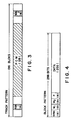
- Fig. 3 is an explanatory view showing a single track pattern formed in a slanting manner on the magnetic tape.
- This single track pattern is composed of 196 blocks wherein subcodes SUB-1, 2 are recorded on a portion of a fixed period from the initial end and a portion of a fixed period immediately before the terminating end, respectively, and PCM signal data PCM are recorded on the track intermediate portion except for the above portions.
- the subcodes SUB-1, 2 are composed of 8 blocks, respectively, and the PCM signal data PCM is composed of 128 blocks.
- Fig. 4 is an explanatory view showing one block pattern comprised of 288 bits. As shown, from the initial end, a synchronizing signal of 8 bits, an ID code W1 of 8 bits, a block address W2 of 8 bits, a parity P of 8 bits, and data of 256 bits are arranged in succession in order recited.
- the ID code W1 serves as "PCM-ID” in the PCM signal data PCM of the track pattern and also serves as "SUB-ID” in the subcode SUB-1 thereof.
- Fig. 5 is an explanatory view showing the data configuration of PCM-ID which is ID code W1, and a block address W2 in the PCM signal data PCM of the track pattern.
- ID-1 to ID-8 are indispensable data which are called "items of MUST".
- ID code W1 PCM-ID
- optional code is constituted in accordance with a format as shown in Fig. 6.
- the optional code is comprised of search codes SC1 to SC4 and auxiliary codes AC1 to AC4. Further, the higher order 4 bits of the auxiliary code AC1 is allocated to item. In addition, lower order 4 bits of the auxiliary code AC1, and higher order and lower order 4 bits of the auxiliary codes AC2 to AC4 are allocated to data N1 to N6 and parity P, respectively.
- Fig. 7 is an explanatory view showing the configuration of the item of the auxiliary code AC1.
- the same identification codes I as the specific identification number i allocated to the DAT equipment Si are recorded on the data N1 to N6 and their parity as specified item ⁇ e.g., "Reserved item” or "Catalog item” ⁇ of the auxiliary code AC1 (Fig. 7) of the optional code (Fig. 6) of the PCM-ID (Fig. 5) in the above-mentioned track pattern (format) recorded on the magnetic tape.
- Fig. 1 is a block diagram showing an embodiment of an apparatus for recording and reproducing a digital signal.
- a set of rotary heads 2 and 2 are affixed at positions opposite to each other on the rotary drum 1.
- a magnetic tape 3 is, e.g., 3.81 mm wide and is wound onto the rotary drum 1 with it being obliquely contact therewith over an angular range of 90 degrees with respect to the rotary drum 1.
- the magnetic tape 3 is caused to run in a direction indicated by an arrow with it being tightly supported by a capstan and a pinch roller (which are not shown).
- the set of rotary heads 2 and 2 have gaps of which azimuth angles are opposite to each other. They have a track width broader (e.g. 1.5 times) than that of the recording track and is revolved in a body with the rotary drum 1.
- This digital signal recording/reproducing apparatus is provided with an input terminal 4 to which an analog audio signal is input, an input terminal 5 to which a digital audio signal reproduced from CD, etc. is input, an output terminal 6 from which an analog audio signal is output, and an output terminal 7 from which a digital audio signal is output.
- an analog audio input signal from the input terminal 4 is delivered to a digital signal processing circuit 10 through an amplifier 8 and an A/D converter 9 and through the terminal a of a changeover switch S.
- a digital audio input signal from the input terminal 5 is also delivered to the digital signal processing circuit 10 through the terminal b of the changeover switch S.
- a digital signal output from the digital signal processing circuit 10 is changed to an analog signal by a D/A converter 11 and the analog signal thus obtained is then output as an analog audio signal to the output terminal 6 through an amplifier 12.
- the same digital signal as stated above which is output from the digital signal processing circuit 10 is directly output to the output terminal 7 as a digital audio signal.
- the digital signal recording/reproducing apparatus further comprises a subcode memory 13, an interface 14, a microcomputer 15, and a non-volatile memory or switch 16.
- Subcode includes not only subcodes recorded on the subcode areas SUB-1, 2, but also PCM-ID recorded on the PCM area in this specification. Subcodes including PCM-ID to be recorded or reproduced are memorized into the subcode memory 13.
- the digital signal processing circuit 10 adds error correcting codes C1 and C2 (both of which are read-solomon code) to a digital signal delivered through the A/D converter 9 at the time of recording or a digital audio signal (including at least two channel data of Right and Left) reproduced from CD, etc. delivered from the input terminal 5 to generate PCM data, and adds the error correcting code C1 to a portion of data sent from the subcode memory 13 and adds an error detection simple parity code to the remaining portion thereof.
- PCM audio data and subcode data are formated so as to have forms allocated thereto, respectively, these formated data are subjected to modulation (8 to 10 conversion) so as to have form easy to effect data transmission.
- An Automatic Track Finding (ATF) signals are added thereto, thus to generate a digital signal for recording onto the magnetic tape 3 to deliver it to the rotary heads 2 and 2.
- the digital signal processing circuit 10 takes out a signal reproduced from the magnetic tape 3 to make an error correction, thus to generate a digital audio signal.
- this circuit 10 makes an error correction of a portion of subcodes SUB-1, 2 on the subcode areas and PCM-ID on the PCM area of the magnetic tape 3 and carries out an error detection of the remaining portion thereof, thus to write corrected data into the subcode memory 13.
- the subcode memory 13 serves to store data of subcode. At the time of recording, the signal flows via the microcomputer 15, the interface 14, the subcode memory 13, and the digital signal processing circuit 10. In contrast, at the time of reproduction, the signal flows in an opposite direction via the digital signal processing circuit 10, the subcode memory 13, the interface 14, and the microcomputer 15.
- the interface 14 is a circuit for effecting reception and transmission of data among the microcomputer 15, the subcode memory 13, and the non-volatile memory or switch 16.
- the non-volatile memory or siwtch 16 is a memory or a switch for memorizing a specific identification number allocated to the DAT equipment concerned.
- Fig. 1A is a block diagram showing the detail of the circuit in Fig. 1. This circuit has a configuration different from that in Fig. 1 in part.
- the data processing circuit 10 comprises, in the same manner as in the ordinary DAT equipment, a circuit element or component for delivering an input from the digital input 5 or the analog input 4 to the magnetic head 2 to record it thereon and a circuit component for producing a signal taken out from the magnetic head 2 on the digital output 7 or the analog output 6 as a reproduced output.
- a recording signal processing circuit 102 applies interleave or addition or error detecting/correcting code, etc. to the PCM audio signal to add a subcode from the subcode memory 13 thereto, thereafter to deliver the signal thus obtained to the magnetic tape 2 through an amplifier and a mode changeover switch 101.
- a regenerative signal processing circuit 103 for the reproducing element, a regenerative signal processing circuit 103, a subcode identification circuit 106, and a mute circuit 104 are provided.
- PCM data in teh signal reproduced by the magnetic head 2 is subjected to error detection/correction by the regenerative signal processing circuit 103 and the data thus processed is delivered to the mute circuit 104.
- the subcode signal in the reproduced signal is delivered to the subcode identification circuit 106, at which the kind of the subcode is identified.
- the subcode signal thus identified is stored at a predetermined address in the subcode memory 13 allocated in advance in correspondence with the kind identified.
- the microcomputer 15 reads the reproduced subcode stored in the subcode memory 13 through a section 141 (I/F-1) of the interface 14 according to need, thus to display reproducing mode, program number, and performance passing time, etc. on a display (not shown).
- a mute signal is delivered from the ⁇ -com 15 to the mute circuit 104, thus to mute off an output signal.
- a changeover circuit 105 operated by a mode switch signal from the ⁇ -com 15 is provided.
- this changeover circuit 15 detects a sampling frequency from the DAI 17 to deliver the signal detected to the ⁇ -com 15.
- this changeover circuit 105 selects and switches a sampling frequency according to the mode from a plurality of sampling signals obtained by frequency-dividing a signal from an oscillator 107 using a frequency-dividing circuit 108, thus to deliver it to the A/D converter 9 or to the DAI 18 and the D/A converter 11.
- DAIs 17 and 18 in Fig. 1A are not provided in the circuit configuration in Fig. 1, which are constituted in accordance with EIAJ standard, CP-340, Digital Audio Interface (instituted Sept., 1987).
- This digital signal processing circuit 10 is controlled by the ⁇ -com 15.
- the ⁇ -com 15 responds to, as a key input, an analog/didital input switch command by a push-button switch 19A and a recording/reproducing switch command by another push button switch 19B to carry out determination of mode by the level judgement. Further, the ⁇ -com 15 makes a judgement whether the magnetic tape is a pre-recorded tape on the basis of an input by the Recognition switch 20.
- This Recognition switch 20 is automatically opened and closed in dependence upon whether or not a recognition hole for a pre-recorded tape is provided at a predetermined portion of the tape cassette loaded on the DAT equipment.
- the code setting circuit 16 is comprised of a plurality of switches accommodated in a portion where a user is unable to readily access, and a plurality of registers. One terminal of each switch is grounded and the other terminal thereof is connected to a high voltage power supply and to the interface unit 142. Switches combined in correspondence with identification code particular to the DAT equipment are set OFF. Other switches are set ON.
- the code setting circuit 16 delivers a high or low level signal parallelly to the interface unit 142 in dependence upon the set condition of OFF or ON of these switches.
- the interface unit 142 receives a command (a load signal and a read clock) from the ⁇ -com 15 to convert parallel identification code signals from the code setting circuit 16 to a serial identification code signal, thus to deliver it to the ⁇ -com 15.
- the ⁇ -com 15 delivers the identification code thus delivered to the memory 13 through the interface unit 141 to memorize it at a predetermined address (step 23 in Fig. 2).
- the ⁇ -com 15 further delivers it to the recording signal processing circuit 102 to record it on the tape along with PCM data and other subcodes.
- the ⁇ -com 15 resets (clears) the data at the predetermined address mentioned above of the subcode memory 13 (step 25).
- the ⁇ -com 15 reads data at the predetermined address of the subcode memory 13 through the interface unit 141 to judge whether or not an identification code is present thereat (step 28). As a result, when the identification code is present, this code is compared with an identification code obtained from the code setting circuit 16 through the interface unit 142 (step 29).
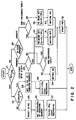
- the ⁇ -com 15 is programmed so that it makes a judgment in accordance with the flowchart shown in Fig. 2, or controls respective elements. Since the operations at respective steps are the same as those in ordinary DAT equipment and the whole operation becomes apparent from the flowchart in Fig. 2, further explanation in regard to Fig. 1A will be omitted.
- step 21 judgement as to whether the apparatus is in a recording or reproducing (playback) mode is made (step 21).
- judgement as to whether or not the sampling frequency fs is 44.1 KHz is made (step 22).
- the same identification code as the specific identification number allocated to the DAT equipment concerned is set at the subcode memory 13 (step 23).
- the sampling frequency fs is allowed to be equal to 44.1 KHz to start recording (step 24).
- the identification code is reset (step 25). Then, a sampling frequency fs except for 44.1 KHz is set at the subcode memory 13 (step 26). Then, the sampling frequency fs is allowed to be equal to a value except for 44.1 KHz to start recording (step 27).
- step 28 judgement as to whether or not an identification code in the reproduced signal is present is made (step 28).
- step 29 judgement as to whether that identification code is coincident with the own identification number allocated to the DAT equipment concerned is made (step 29).
- the sampling frequency fs is set to 44.1 KHz (step 30).
- muting is turned off (step 31) to start reproduction or playback (step 32).
- step 34 discrimination as to whether the magnetic tape is a pre-recorded tape by the detection hole (Recognition hole) provided in the magnetic tape cassette is made in the same manner as in the step 33 (step 35).
- the program execution shifts to the step 30.
- the sampling frequency is set to a value except for 44.1 KHz (step 36) to turn on muting (step 37).
- the program execution shifts to the above-mentioned step 32.
- an apparatus for recording and reproducing a digital signal is adapted so that, when an input digital signal is recorded on a recording medium to reproduce it therefrom, reproduction is possible with the apparatus thus recorded whereas reproduction is impossible with a recording/reproducing apparatus and a reproducing apparatus except for the above apparatus.
- a recording/reproducing apparatus and a reproducing apparatus except for the above apparatus.
Landscapes
- Engineering & Computer Science (AREA)
- Computer Security & Cryptography (AREA)
- Signal Processing (AREA)
- Multimedia (AREA)
- Signal Processing For Digital Recording And Reproducing (AREA)
Claims (4)
- Gerät zur Aufzeichnung von digitalen Signalen auf einem Aufzeichnungsmedium (3) und zur Wiedergabe von darauf aufgezeichneten digitalen Signalen, wobei das Gerät aufweist:
eine Codeaufzeichnungsvorrichtung (16,102) zur Aufzeichnung eines Identifikationscodes, der eine für dieses Digitalsignalaufzeichnungs- und -wiedergabegerät spezielle Identifikationsnummer ist, auf dem Aufzeichnungsmedium; und
eine Codewiedergabevorrichtung (103) zur Wiedergabe eines aufgezeichneten Identifikationscodes zum Zeitpunkt der Wiedergabe von aufgezeichneten digitalen Signalen zum Vergleichen des wiedergegebenen Identifikationscodes mit der speziellen Identifikationsnummer für dieses Digitalsignalaufzeichnungs- und -wiedergabegerät und zur Gewährung eines Zugriffs auf die digitalen Daten im Falle einer Übereinstimmung,
gekennzeichnet durch eine Frequenzdetektoreinrichtung (105), die ermittelt, ob aufzuzeichnende digitale Eingangssignale eine digitale Aufzeichnung von mit einer vorbestimmten Abtastfrequenz abgetasteten analogen Daten darstellen; wobei die Codeaufzeichnungsvorrichtung auf die Frequenzdetektoreinrichtung anspricht, um den Identifikationscode nur aufzuzeichnen, wenn die digitalen Eingangssignale eine digitale Aufzeichnung von mit der vorbestimmten Abtastfrequenz abgetasteten analogen Daten darstellen, und so wirksam ist, daß sie den Identifikationscode bei wiederholten Intervallen auf dem Aufzeichnungsmedium zwischen Blöcken von aufgezeichneten digitalen Daten aufzeichnet; und wobei die Codewiedergabevorrichtung (103) so wirksam ist, daß sie die Wiedergabe eines auf einem Aufzeichnungsmedium aufgezeichneten digitalen Eingangssignals, das ferner einen für ein digitales Aufzeichnungs- und Wiedergabegerät speziellen Identifikationscode enthält, nur dann zuläßt, wenn der wiedergegebene Identifikationscode mit dem für dieses Digitalsignalaufzeichnungs- und -wiedergabegerät speziellen Identifikationscode übereinstimmt. - Gerät zur Aufzeichnung und Wiedergabe eines digitalen Signals nach Anspruch 1, in welchem die Codeaufzeichnungsvorrichtung eine Codeerzeugungseinrichtung (16) aufweist, die einen Identifikationscode bildet, der speziell für dieses Digitalsignalaufzeichnungs- und -wiedergabegerät ist; und eine Aufzeichnungseinrichtung (1,2) aufweist, die den Identifikationscode von der Codeerzeugungseinrichtung auf dem Aufzeichnungsmedium (3) aufzeichnet, wenn die Frequenzdetektoreinrichtung detektiert, daß die Abtastfrequenz des digitalen Eingangssignals die vorbestimmte Frequenz ist.
- Verfahren zur Aufzeichnung eines digitalen Signals auf einem Aufzeichnungsmedium und zur Wiedergabe eines aufgezeichneten Signals hiervon, wobei das Verfahren umfaßt:
Aufzeichnen eines Identifikationscodes, der eine für das Digitalsignalaufzeichnungs- und -wiedergabegerät, das zur Ausführung der Aufzeichnung verwendet wird, spezielle Identifikationsnummer ist, auf dem Aufzeichnungsmedium; und
Wiedergeben des Identifikationscodes zum Zeitpunkt der Wiedergabe von auf dem Aufzeichnungsmedium aufgezeichneten digitalen Signalen, Vergleichen des wiedergegebenen Identifikationscodes mit der speziellen Identifikationsnummer für dieses digitale Aufzeichnungs- und Wiedergabegerät und Gewährung eines Zugriffs auf das digitale Signal im Falle einer Übereinstimmung,
dadurch gekennzeichnet, daß der Aufzeichnungsschritt beinhaltet:
Ermitteln, ob aufzuzeichnende digitale Eingangssignale eine digitale Aufzeichnung von mit einer vorbestimmten Abtastfrequenz abgetasteten analogen Daten darstellen;
Aufzeichnen des Identifikationscodes auf dem Aufzeichnungsmedium nur, wenn die digitalen Eingangssignale eine digitale Aufzeichnung von mit der vorbestimmten Abtastfrequenz abgetasteten analogen Daten darstellen, wobei der Identifikationscode bei wiederholten Intervallen auf dem Aufzeichnungsmedium zwischen Blöcken von aufgezeichneten digitalen Daten aufgezeichnet wird;
und daß der Wiedergabeschritt beinhaltet:
Zulassen der Wiedergabe eines auf einem Aufzeichnungsmedium aufgezeichneten digitalen Eingangssignals, das ferner einen für ein digitales Aufzeichnungs- und Wiedergabegerät speziellen Identifikationscode enthält, nur dann, wenn der wiedergegebene Identifikationscode mit dem für dieses Aufzeichnungs- und Wiedergabegerät speziellen Identifikationscode übereinstimmt. - Verfahren nach Anspruch 3, in welchem digitale Information in auf dem Aufzeichnungsmedium definierten Spuren aufgezeichnet wird und die Spuren in eine Anzahl von Blöcken aufgeteilt sind, wobei jeder Block einen für aufgezeichnete digitale Daten reservierten ersten Abschnitt und einen zweiten Abschnitt aufweist, der für andere vom Aufzeichnungs- und Wiedergabegerät zu identifizierende Betriebsdaten reserviert ist, wobei der Identifikationscode auf dem zweiten Abschnitt jedes Blocks aufgezeichnet wird.
Applications Claiming Priority (2)
| Application Number | Priority Date | Filing Date | Title |
|---|---|---|---|
| JP87515/87 | 1987-04-09 | ||
| JP62087515A JPS63253568A (ja) | 1987-04-09 | 1987-04-09 | デジタル信号記録再生装置 |
Publications (3)
| Publication Number | Publication Date |
|---|---|
| EP0286437A2 EP0286437A2 (de) | 1988-10-12 |
| EP0286437A3 EP0286437A3 (en) | 1990-01-24 |
| EP0286437B1 true EP0286437B1 (de) | 1994-01-12 |
Family
ID=13917127
Family Applications (1)
| Application Number | Title | Priority Date | Filing Date |
|---|---|---|---|
| EP88303182A Expired - Lifetime EP0286437B1 (de) | 1987-04-09 | 1988-04-08 | Gerät und Verfahren zur Aufzeichnung und Wiedergabe eines digitalen Signals |
Country Status (5)
| Country | Link |
|---|---|
| US (1) | US4901168A (de) |
| EP (1) | EP0286437B1 (de) |
| JP (1) | JPS63253568A (de) |
| CA (1) | CA1329654C (de) |
| DE (1) | DE3886972T2 (de) |
Families Citing this family (9)
| Publication number | Priority date | Publication date | Assignee | Title |
|---|---|---|---|---|
| US5199066A (en) * | 1989-04-18 | 1993-03-30 | Special Effects Software, Inc. | Method and apparatus for protecting software |
| US5295023A (en) * | 1991-02-28 | 1994-03-15 | Sony Corporation | Digital signal recording apparatus for analog/digital input |
| JP3084969B2 (ja) * | 1992-10-16 | 2000-09-04 | 松下電器産業株式会社 | 再生装置と記録装置とケース入り記録媒体と記録媒体の初期化装置 |
| GB9405753D0 (en) * | 1994-03-23 | 1994-05-11 | Gms Recordings Limited | Interactive compact disk system |
| JPH08287603A (ja) * | 1995-04-13 | 1996-11-01 | Pioneer Electron Corp | 情報記録装置及び情報再生装置 |
| JPH09297798A (ja) * | 1996-05-08 | 1997-11-18 | Matsushita Electric Ind Co Ltd | マルチメディア機器のコピー防止装置 |
| DE19743002A1 (de) * | 1997-09-29 | 1999-04-08 | Siemens Ag | Umschaltvorrichtung für analoge und digitale Signale |
| GB9804766D0 (en) * | 1998-03-06 | 1998-04-29 | Mumford Ray | CD Copy protection |
| JP2001005499A (ja) * | 1999-04-23 | 2001-01-12 | Matsushita Electric Ind Co Ltd | 音楽データ情報伝送方法および装置 |
Family Cites Families (7)
| Publication number | Priority date | Publication date | Assignee | Title |
|---|---|---|---|---|
| AU547877B2 (en) * | 1980-09-26 | 1985-11-07 | B. Lofberg | Method for processing an information signal and means for carrying out the method |
| EP0084441A3 (de) * | 1982-01-19 | 1984-08-22 | Tabs Limited | Verfahren und Einrichtung zur Sicherung von Computer-Software-Eigentum |
| FR2528196B1 (fr) * | 1982-06-07 | 1988-05-27 | Fortune Systems Corp | Appareil de protection de programmes d'ordinateur |
| JPS5960464A (ja) * | 1982-09-30 | 1984-04-06 | 株式会社東芝 | プログラムの暗号化方式 |
| DE3511674A1 (de) * | 1985-03-29 | 1986-10-02 | Hermann 7742 St Georgen Stockburger | System mit einem geraet mit einer datenverarbeitungseinrichtung |
| US4688169A (en) * | 1985-05-30 | 1987-08-18 | Joshi Bhagirath S | Computer software security system |
| US4796220A (en) * | 1986-12-15 | 1989-01-03 | Pride Software Development Corp. | Method of controlling the copying of software |
-
1987
- 1987-04-09 JP JP62087515A patent/JPS63253568A/ja active Pending
-
1988
- 1988-04-08 DE DE88303182T patent/DE3886972T2/de not_active Expired - Fee Related
- 1988-04-08 EP EP88303182A patent/EP0286437B1/de not_active Expired - Lifetime
- 1988-04-08 CA CA000563639A patent/CA1329654C/en not_active Expired - Fee Related
- 1988-04-11 US US07/180,059 patent/US4901168A/en not_active Expired - Fee Related
Also Published As
| Publication number | Publication date |
|---|---|
| JPS63253568A (ja) | 1988-10-20 |
| US4901168A (en) | 1990-02-13 |
| CA1329654C (en) | 1994-05-17 |
| DE3886972T2 (de) | 1994-04-28 |
| EP0286437A2 (de) | 1988-10-12 |
| DE3886972D1 (de) | 1994-02-24 |
| EP0286437A3 (en) | 1990-01-24 |
Similar Documents
| Publication | Publication Date | Title |
|---|---|---|
| AU634709B2 (en) | Recording system as well as record carrier and recording apparatus for use in the system | |
| EP0418964B1 (de) | Aufzeichnungsträger, Verfahren und Informationsaufzeichnungsanordnung zum Erhalten derartiger Aufzeichnungsträger, sowie Informationsaufzeichnungsanordnung mit Antikopiermitteln zum Verhindern ungewünschter Kopiervorgänge | |
| KR930001492B1 (ko) | 기록 재생장치 | |
| JP2725257B2 (ja) | ディジタル記録装置 | |
| EP0286437B1 (de) | Gerät und Verfahren zur Aufzeichnung und Wiedergabe eines digitalen Signals | |
| JP4616944B2 (ja) | 担体に情報を記録する方法及び装置 | |
| JP2767795B2 (ja) | ディジタルインターフェース | |
| JP2651437B2 (ja) | デジタルテープレコーダにおけるプログラム監視装置 | |
| JPH05266586A (ja) | デジタル・オーディオ記録再生方式 | |
| JPH0991869A (ja) | ディジタル信号記録装置 | |
| EP0504429A1 (de) | Aufzeichnungs- und wiedergabegerät für platten | |
| JP2982224B2 (ja) | Vtr | |
| JP3369836B2 (ja) | 記録再生装置および記録再生方法 | |
| JPS637585A (ja) | 磁気記録装置 | |
| KR100794550B1 (ko) | 디스크 레코더에서의 동기 기록장치 및 방법 | |
| KR100790036B1 (ko) | 디스크 레코더에서의 동기 기록방법 | |
| JP2805703B2 (ja) | データ記録方法 | |
| JPH056633Y2 (de) | ||
| JPS62232772A (ja) | Pcm信号記録再生装置 | |
| JPH01285063A (ja) | 磁気記録再生方式 | |
| JPH0711899B2 (ja) | 記録再生装置、再生装置、記録装置、再生媒体、及び伝送方式 | |
| JPH02158959A (ja) | ディジタルオーディオテープレコーダ | |
| JPH0426953A (ja) | 情報記録装置 | |
| JPS60151875A (ja) | デイジタル記録再生方式 | |
| JPH04143987A (ja) | 区切り信号生成装置 |
Legal Events
| Date | Code | Title | Description |
|---|---|---|---|
| PUAI | Public reference made under article 153(3) epc to a published international application that has entered the european phase |
Free format text: ORIGINAL CODE: 0009012 |
|
| AK | Designated contracting states |
Kind code of ref document: A2 Designated state(s): DE FR GB |
|
| PUAL | Search report despatched |
Free format text: ORIGINAL CODE: 0009013 |
|
| AK | Designated contracting states |
Kind code of ref document: A3 Designated state(s): DE FR GB |
|
| 17P | Request for examination filed |
Effective date: 19900307 |
|
| 17Q | First examination report despatched |
Effective date: 19911001 |
|
| GRAA | (expected) grant |
Free format text: ORIGINAL CODE: 0009210 |
|
| AK | Designated contracting states |
Kind code of ref document: B1 Designated state(s): DE FR GB |
|
| REF | Corresponds to: |
Ref document number: 3886972 Country of ref document: DE Date of ref document: 19940224 |
|
| ET | Fr: translation filed | ||
| PLBE | No opposition filed within time limit |
Free format text: ORIGINAL CODE: 0009261 |
|
| STAA | Information on the status of an ep patent application or granted ep patent |
Free format text: STATUS: NO OPPOSITION FILED WITHIN TIME LIMIT |
|
| 26N | No opposition filed | ||
| PGFP | Annual fee paid to national office [announced via postgrant information from national office to epo] |
Ref country code: GB Payment date: 19960401 Year of fee payment: 9 |
|
| PGFP | Annual fee paid to national office [announced via postgrant information from national office to epo] |
Ref country code: FR Payment date: 19960410 Year of fee payment: 9 |
|
| PGFP | Annual fee paid to national office [announced via postgrant information from national office to epo] |
Ref country code: DE Payment date: 19960418 Year of fee payment: 9 |
|
| PG25 | Lapsed in a contracting state [announced via postgrant information from national office to epo] |
Ref country code: GB Effective date: 19970408 |
|
| GBPC | Gb: european patent ceased through non-payment of renewal fee |
Effective date: 19970408 |
|
| PG25 | Lapsed in a contracting state [announced via postgrant information from national office to epo] |
Ref country code: FR Free format text: LAPSE BECAUSE OF NON-PAYMENT OF DUE FEES Effective date: 19971231 |
|
| PG25 | Lapsed in a contracting state [announced via postgrant information from national office to epo] |
Ref country code: DE Free format text: LAPSE BECAUSE OF NON-PAYMENT OF DUE FEES Effective date: 19980101 |
|
| REG | Reference to a national code |
Ref country code: FR Ref legal event code: ST |