EP0286474A1 - Mécanisme de commande d'un interrupteur à trois positions - Google Patents
Mécanisme de commande d'un interrupteur à trois positions Download PDFInfo
- Publication number
- EP0286474A1 EP0286474A1 EP88400592A EP88400592A EP0286474A1 EP 0286474 A1 EP0286474 A1 EP 0286474A1 EP 88400592 A EP88400592 A EP 88400592A EP 88400592 A EP88400592 A EP 88400592A EP 0286474 A1 EP0286474 A1 EP 0286474A1
- Authority
- EP
- European Patent Office
- Prior art keywords
- crank
- axis
- toggle joint
- switch
- lever
- Prior art date
- Legal status (The legal status is an assumption and is not a legal conclusion. Google has not performed a legal analysis and makes no representation as to the accuracy of the status listed.)
- Granted
Links
- 230000007246 mechanism Effects 0.000 title claims abstract description 30
- 230000007935 neutral effect Effects 0.000 claims abstract description 12
- 230000009471 action Effects 0.000 claims description 8
- 230000005540 biological transmission Effects 0.000 claims description 6
- 210000003127 knee Anatomy 0.000 claims description 4
- 230000000903 blocking effect Effects 0.000 claims description 3
- 230000005405 multipole Effects 0.000 claims description 3
- 230000004048 modification Effects 0.000 claims description 2
- 238000012986 modification Methods 0.000 claims description 2
- 230000008878 coupling Effects 0.000 description 2
- 238000010168 coupling process Methods 0.000 description 2
- 238000005859 coupling reaction Methods 0.000 description 2
- 238000004146 energy storage Methods 0.000 description 2
- 238000006243 chemical reaction Methods 0.000 description 1
- 230000006835 compression Effects 0.000 description 1
- 238000007906 compression Methods 0.000 description 1
- 238000010586 diagram Methods 0.000 description 1
- 230000000284 resting effect Effects 0.000 description 1
Images


Classifications
-
- H—ELECTRICITY
- H01—ELECTRIC ELEMENTS
- H01H—ELECTRIC SWITCHES; RELAYS; SELECTORS; EMERGENCY PROTECTIVE DEVICES
- H01H3/00—Mechanisms for operating contacts
- H01H3/22—Power arrangements internal to the switch for operating the driving mechanism
- H01H3/30—Power arrangements internal to the switch for operating the driving mechanism using spring motor
- H01H3/3047—Power arrangements internal to the switch for operating the driving mechanism using spring motor adapted for operation of a three-position switch, e.g. on-off-earth
Definitions
- the invention relates to a control mechanism of a multipole switch capable of occupying three distinct stable positions, in particular a first closed position, a second intermediate open position, and a third earthing position, said mechanism being of the tumbler type comprising: - an energy storage spring associated with a knee switch with abrupt passage from neutral, provided with an actuating lever articulated on an axis of a first control crank, - a main operating crank fixed to a rotary shaft secured to the moving part of the switch, - a grounding crank mounted with limited rotation on a first control axis between a rest position when the main crank is moved by the toggle between the closed and open positions, and an active position for setting earth causing a modification of the fulcrum and the line of action of the spring causing the continued rotation of the main crank beyond the open position to the earth position, - And means for blocking the main crank in each of the three positions of the switch.
- a known mechanism of the kind mentioned is described in detail in French patent No. 2,500,222 of the applicant.
- a single energy storage spring is sufficient to activate the switch in one of the three positions.
- the opening and closing control axis coincides with the shaft of the operating cam of the drive lever of the moving element.
- the knee lever actuation lever is arranged between the shaft of the operating cam, and the control axis of the crank grounding. This results in a lateral overflow of the control lever when it is introduced on one of the two control axes.
- the release of the maneuvering cam takes place after the neutral point of the toggle joint has been exceeded thanks to the reaction force of a ramp on a cleat of a spring-loaded retaining crank.
- the ramp and spring-loaded retaining crank assembly does not constitute a positive coupling of the cam, since the unlocking occurs when the driving torque of the cam actuated by the toggle outweighs the resistant torque of the retaining crank.
- the object of the invention is to provide a compact control mechanism, with positive coupling of the operating crank.
- the mechanism according to the invention is characterized in that a second axis for controlling the opening and closing of the mechanism is offset from the operating shaft by cooperating with a kinematic chain capable of rotating the first control crank of the toggle joint and a lever for hooking the main crank is actuated automatically to an unlocking position when the knee lever is in the vicinity of neutral.
- the erasure of the hooking lever occurs advantageously by the mechanical action of a boss located on the first crank of the toggle joint, the unlocking intervening when the line of action of the spring is placed in alignment with the shaft of maneuver and the pivot pin of the toggle.
- the energy accumulated in the actuating spring of the mechanism is maximum at this instant of release of the main crank.
- the kinematic chain for returning the opening and closing control movements of the second axis comprises a link articulated to a second transmission crank capable of cooperating with a drive stopper of the first crank of the kneepad.
- the second crank of the kinematic chain is mounted coaxially on the shaft with the first crank of the toggle.
- the position of the switch contacts is displayed by means of an indicator fixed directly on the operating shaft.
- a spring-loaded control mechanism 12 accumulator is housed between a pair of plates 14 supports, and is used to actuate a multipole electric switch incorporated in a switching cell.
- the switch is electrically connected between a busbar and connection cables (not shown), and can occupy three distinct positions, in particular a first service position F by closing the contacts, a second intermediate position O isolated by opening contacts, and a third cable earth position T.
- the mechanism 10 is of the single spring tumbler type 12 and with a sudden overrun of neutral position by means of a toggle switch 16 comprising an actuating lever 18 articulated on an axis 20 of a first control crank 22.
- the axis 20 of the toggle joint 16 cooperates with a cam 24 forming part of a main operating crank 26 fixed on a rotary shaft 28, integral with the movable assembly of the different poles of the switch.
- the cam 24 has a curvilinear profile centered on the shaft 28 and delimited by two spaced notches 30, 32 constituting stops for the axis 20 in each stable position of the toggle joint 16.
- the compression spring is threaded on the lever 18, by resting on a fixed shoulder 34 of the latter, and an axis 36 of a crank 38 for earthing control.
- the earthing operation by the crank 38 is carried out by means of a transmission rod 40, one end of which has an oblong hole 42 in which a first crank pin 44 of the crank 38 is engaged. the earth, and the opposite end of which carries a second crank pin 46 capable of moving in a curvilinear groove 48.
- the latter is formed in an auxiliary blocking crank 50 ensuring the stopping of the angular travel of the main crank 26 when the switch arrives in the positions O of opening and T of earthing.
- the earthing crank 38 is integral with a first rotary control axis 52 which can be rotated between the open positions O and earthing T.
- the angular travel of the crank 38 is limited by two stop blocks 54, 56.
- the auxiliary locking crank 50 cooperates with a stop 60 and is mounted on an axis 58 extending parallel to the operating shaft 28.
- the opening and closing operation of the switch is effected by means of a control lever (not shown) introduced on a second control axis 62 offset from the pole control shaft 28 .
- the control movement is returned by means of a kinematic chain 64 comprising a link 66 articulated by its opposite ends, respectively to a third control crank 68 wedged on the rotary axis 62, and to a second crank 70 of transmission mounted in free rotation on the shaft 28.
- the crank 22 of the toggle joint 16 is mounted loosely on the shaft 28, and includes a driving cleat 72 capable of cooperating with the crank 70 of transmission when the switch is closed and opened.
- a hooking lever 78 is pivotally mounted on an axis 80 between a locked position and an unlocked position, and comprises a retaining stud 82 intended to snap into the locked position on a step 84, 86 of the main crank 26 of maneuver.
- a torsion spring 88 is inserted on the axis 80 and biases the latching lever 78 towards the locked position (fig. 1 and 2).
- the presence of the lever 78 ensures in the locked position a positive attachment of the main crank 26 before the neutral switch of the toggle switch 16 intervening during the opening and closing strokes.
- the release of the crank 26 by unlocking of the lever 78 takes place automatically in the vicinity of the crossing of the neutral point thanks to the action of a boss 90 (FIG. 4) belonging to the crank 22 of the toggle joint 16.
- An indicator (not shown) is fixed directly to the operating shaft 28, so as to display the actual position of the switch contacts.
- the main operating crank 26 is in stable abutment against a stop 92, and is locked in this position by the latching lever 78, the stud 82 of which blocks the step 84 by preventing the main crank 26 from rotating in the trigonometric direction .
- the pivot pin 20 of the toggle joint 16 is positioned in the notch 32 of the cam 24, and the earthing crank 38 is held against the lower stop cleat 54 by the action of the spring 12.
- the switch is opened by engaging a control lever on the axis 62, followed by a rotation of the crank 68 in the counterclockwise direction indicated by the arrow 0 (fig. 5).
- the kinematic chain 64 moves the transmission crank 70 in a trigonometric direction, which in the same direction drives the cleat 72 of the crank 22 of the toggle joint 16.
- the pivot axis 20 of the toggle joint 16 goes up along the cam 24 , while the main crank 26 remains blocked in the position of FIG. 1 by the locking action of the latching lever 78.
- cranks 38 and 50 and the link rod 40 remain stationary during the opening and closing movements of the mechanism 10.
- the offset of the control axis 62 relative to the shaft 28 for maneuvering the moving element avoids any lateral overflow of the control lever.
- the closing and opening of the switch by unlocking the latching lever 78 of the mechanism 10 to be tumbled occurs at precise times when the energy stored in the accumulator spring 12 is maximum.
- the cables are earthed from the open position O (fig. 2 and 6) by actuating the pin 52 of operating the crank 38 clockwise, indicated by the arrow FT in fig. 6.
- This operation is analogous to that described in the mechanism of the aforementioned French patent No. 2,500,222.
- the lever 78 remains inactive during this operating phase, and authorizes the tilting of the main crank 26 towards the position T (fig. 3 and 7).
Landscapes
- Mechanisms For Operating Contacts (AREA)
- Driving Mechanisms And Operating Circuits Of Arc-Extinguishing High-Tension Switches (AREA)
- Steering Devices For Bicycles And Motorcycles (AREA)
- Harvester Elements (AREA)
Abstract
Description
- L'invention est relative à un mécanisme de commande d'un interrupteur multipolaire susceptible d'occuper trois positions distinctes stables, notamment une première position de fermeture, une deuxième position intermédiaire d'ouverture, et une troisième position de mise à la terre, ledit mécanisme étant du type tumbler comportant :
- un ressort accumulateur d'énergie associé à une genouillère à passage brusque de point mort, pourvue d'un levier d'actionnement articulé sur un axe d'une première manivelle de commande,
- une manivelle principale de manoeuvre fixée sur un arbre rotatif solidaire de l'équipage mobile de l'interrupteur,
- une manivelle de mise à la terre montée à rotation limitée sur un premier axe de commande entre une position de repos lorsque la manivelle principale est déplacée par la genouillère entre les positions de fermeture et d'ouverture, et une position active de mise à la terre provoquant une modification du point d'appui et de la ligne d'action du ressort entraînant la rotation poursuivie de la manivelle principale au-delà de la position d'ouverture vers la position de mise à la terre,
- et des moyens de blocage de la manivelle principale dans chacune des trois positions de l'interrupteur. - Un mécanisme connu du genre mentionné est décrit en détail dans le brevet français No. 2.500.222 de la demanderesse. Un seul ressort accumulateur d'énergie est suffisant pour actionner l'interrupteur dans l'une des trois positions. L'axe de commande d'ouverture et de fermeture est confondu avec l'arbre de la came de manoeuvre du levier d'entraînement de l'équipage mobile. Le levier d'actionnement de la genouillère est agencé entre l'arbre de la came de manoeuvre, et l'axe de commande de la manivelle de mise à la terre. Il en résulte un débordement latéral du levier de commande lorsqu'il est introduit sur l'un des deux axes de commande. Le déblocage de la came de manoeuvre intervient après le dépassement du point mort de la genouillère grâce à la force de réaction d'une rampe sur un taquet d'une manivelle de retenue à ressort. L'ensemble rampe et manivelle de retenue à ressort ne constitue pas un accrochage positif de la came, étant donné que le déblocage intervient lorsque le couple moteur de la came actionnée par la genouillère l'emporte sur le couple résistant de la manivelle de retenue.
- L'objet de l'invention consiste à réaliser un mécanisme de commande compact, à accrochage positif de la manivelle de manoeuvre.
- Le mécanisme selon l'invention est caractérisé en ce qu'un deuxième axe de commande d'ouverture et de fermeture du mécanisme est décalé de l'arbre de manoeuvre en coopérant avec une chaîne cinématique susceptible d'entraîner en rotation la première manivelle de commande de la genouillère et qu'un levier d'accrochage de la manivelle principale est actionné automatiquement vers une position de déverrouillage lorsque la genouillère se trouve au voisinage du point mort.
- L'effacement du levier d'accrochage intervient avantageusement par l'action mécanique d'un bossage situé sur la première manivelle de la genouillère, le déverrouillage intervenant lorsque la ligne d'action du ressort est placée dans l'alignement avec l'arbre de manoeuvre et l'axe de pivotement de la genouillère. L'énergie accumulée dans le ressort d'actionnement du mécanisme est maximum à cet instant de déblocage de la manivelle principale.
- La chaîne cinématique de renvoi des mouvements de commande d'ouverture et de fermeture du deuxième axe comporte une biellette articulée à une deuxième manivelle de transmision susceptible de coopérer avec un taquet d'entraînement de la première manivelle de la genouillère. La deuxième manivelle de la chaîne cinématique est montée coaxialement sur l'arbre avec la première manivelle de la genouillère.
- La position des contacts de l'interrupteur est visualisée au moyen d'un indicateur fixé directement sur l'arbre de manoeuvre.
- D'autres avantages et caractéristiques ressortiront plus clairement de la description qui va suivre d'un mode de réalisation donné à titre d'exemple non limitatif et représenté aux dessins annexés, dans lesquels :
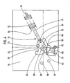
- - la figure 1 est une vue en élévation du mécanisme selon l'invention, correspondant à la position F de fermeture de l'interrupteur;
- - les figures 2 et 3 sont des vues identiques à la figure 1, respectivement en position O d'ouverture, et T de mise à la terre;
- - la figure 4 montre une vue partielle du mécanisme lors du déverrouillage du levier d'accrochage intervenant pendant le passage de la position O d'ouverture vers la position F de fermeture;
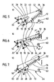
- - les figures 5 à 7 représentent des schémas simplifiés du mécanisme selon les positions respectives des figures 1 à 3.
- Sur les figures, un mécanisme 10 de commande à ressort 12 accumulateur est logé entre une paire de platines 14 supports, et sert à actionner un interrupteur électrique multipolaire incorporé dans une cellule de commutation. L'interrupteur est connecté électriquement entre un jeu de barres et des câbles de raccordement (non représentés), et peut occuper trois positions distinctes, notamment une première position F de service par fermeture des contacts, une deuxième position O intermédiaire d'isolement par ouverture des contacts, et une troisième position T de mise à la terre des câbles.
- Le mécanisme 10 est du type tumbler à ressort 12 unique et à dépassement brusque de point mort par l'intermédiaire d'une genouillère 16 comprenant un levier 18 d'actionnement articulé sur un axe 20 d'une première manivelle 22 de commande. L'axe 20 de la genouillère 16 coopère avec une came 24 faisant partie d'une manivelle 26 principale de manoeuvre fixée sur un arbre 28 rotatif, solidaire de l'équipage mobile des différents pôles de l'interrupteur. La came 24 présente un profil curviligne centré sur l'arbre 28 et délimité par deux encoches 30, 32 espacées constituant des butées pour l'axe 20 dans chaque position stable de la genouillère 16. Le ressort à compression est enfilé sur le levier 18, en prenant appui sur un épaulement 34 fixe de ce dernier, et un axe 36 d'une manivelle 38 de commande de mise à la terre.
- La manoeuvre de mise à la terre par la manivelle 38 s'effectue au moyen d'une tringle 40 de transmission dont l'une des extrémités comporte un trou 42 oblong dans lequel s'engage un premier maneton 44 de la manivelle 38 de mise à la terre, et dont l'extrémité opposée porte un deuxième maneton 46 susceptible de se déplacer dans une rainure 48 curviligne. Cette dernière est ménagée dans une manivelle 50 auxiliaire de blocage assurant l'arrêt de la course angulaire de la manivelle principale 26 lorsque l'interrupteur arrive dans les positions O d'ouverture et T de mise à la terre.
- La manivelle 38 de mise à la terre est solidaire d'un premier axe 52 rotatif de commande pouvant être déplacé en rotation entre les positions d'ouverture O et de mise à la terre T. La course angulaire de la manivelle 38 est limitée par deux taquets d'arrêt 54, 56. Lors du déplacement de l'interrupteur entre les positions F de fermeture et O d'ouverture, la manivelle 38 de mise à la terre reste immobile en appui contre le taquet inférieur 54.
- La manivelle 50 auxiliaire de blocage coopère avec une butée 60 et est montée sur un axe 58 s'étendant parallèlement à l'arbre 28 de manoeuvre.
- Le fonctionnement d'un tel mécanisme à trois positions est analogue à celui décrit dans le brevet français No. 2.500.222.
- Selon l'invention, la manoeuvre d'ouverture et de fermeture de l'interrupteur s'opère au moyen d'un levier de commande (non représenté) introduit sur un deuxième axe 62 de commande décalé de l'arbre 28 de commande des pôles. Le renvoi du mouvement de commande s'effectue par l'intermédiaire d'une chaîne cinématique 64 comprenant une biellette 66 articulée par ses extrémités opposées, respectivement à une troisième manivelle 68 de commande calée sur l'axe rotatif 62, et à une deuxième manivelle 70 de transmission montée en rotation libre sur l'arbre 28.
- La manivelle 22 de la genouillère 16 est montée folle sur l'arbre 28, et comporte un taquet d'entraînement 72 susceptible de coopérer avec la manivelle 70 de transmission lors de la fermeture et de l'ouverture de l'interrupteur. Un ressort de rappel 74 ancré entre la biellette 66 et un point fixe 76 sollicite la chaîne cinématique 64 vers la position O d'ouverture représentée à la figure 2.
- Un levier 78 d'accrochage est monté à pivotement sur un axe 80 entre une position verrouillée et une position déverrouillée, et comporte un téton 82 de retenue destiné à s'encliqueter en position verrouillée sur un redan 84, 86 de la manivelle principale 26 de manoeuvre. Un ressort de torsion 88 est inséré sur l'axe 80 et sollicite le levier d'accrochage 78 vers la position verrouillée (fig. 1 et 2). La présence du levier 78 assure en position verrouillée un accrochage positif de la manivelle principale 26 avant le passage de point mort de la genouillère 16 intervenant pendant les courses d'ouverture et de fermeture. La libération de la manivelle 26 par déverrouillage du levier 78 s'effectue automatiquement au voisinage du franchissement du point mort grâce à l'action d'un bossage 90 (fig. 4) appartenant à la manivelle 22 de la genouillère 16.
- Un indicateur (non représenté) est fixé directement sur l'arbre 28 de manoeuvre, de manière à visualiser la position réelle des contacts de l'interrupteur.
- Le fonctionnement du mécanisme 10 de l'interrupteur selon l'invention est le suivant :
- La manivelle principale 26 de manoeuvre se trouve en appui stable contre une butée 92, et est verrouillée dans cette position par le levier 78 d'accrochage dont le téton 82 bloque le redan 84 en empêchant la rotation de la manivelle principale 26 dans le sens trigonométrique. L'axe 20 de pivotement de la genouillère 16 est positionné dans l'encoche 32 de la came 24, et la manivelle 38 de mise à la terre est maintenue contre le taquet 54 d'arrêt inférieur par l'action du ressort 12.
- A partir de la position F de fermeture, l'ouverture de l'interrupteur s'opère par engagement d'un levier de commande sur l'axe 62, suivi d'une rotation de la manivelle 68 dans le sens trigonométrique indiqué par la flèche 0 (fig. 5). La chaîne cinématique 64 déplace dans le sens trigonométrique la manivelle 70 de transmission, laquelle entraîne dans le même sens le taquet 72 de la manivelle 22 de la genouillère 16. L'axe 20 de pivotement de la genouillère 16 remonte le long de la came 24, alors que la manivelle principale 26 reste bloquée dans la position de la fig. 1 par l'action de verrouillage du levier d'accrochage 78. Lorsque l'axe 20 de la genouillère 16 arrive dans la position instable d'alignement avec l'axe 36 et l'arbre 28, le ressort 12 est comprimé au maximum, et le bossage 90 de la manivelle 22 pousse le levier d'accrochage 78 vers la position déverrouillée, à l'encontre de la force de rappel du ressort 88, provoquant la libération de la manivelle principale 26. Le franchissement du point mort entraîne l'axe 20 de la genouillère 16 vers l'encoche 30 de la came 24, suivi de la détente du ressort 12, et du basculement brusque de la manivelle principale 26 vers la position O d'ouverture (fig. 2 et 6). Dans cette position, la manivelle principale 26 vient en butée contre la manivelle auxiliaire 50 de blocage, et le levier d'accrochage 78 revient en position verrouillée par encliquetage du téton 82 sur le redan 86. Il en résulte un accrochage positif du mécanisme 10 en position d'ouverture.
- Le passage de la position O d'ouverture (fig. 2) vers la position F de fermeture (fig. 1) s'effectue manuellement au moyen du levier par rotation de la manivelle de commande 68 dans le sens des aiguilles d'une montre, indiqué par la flèche F sur la fig. 6. Lorsque la genouillère 16 arrive au passage de point mort (fig. 4), le levier d'accrochage 78 est déverrouillé par le bossage 90 de la manivelle 22. Le franchissement du point mort par l'axe 20 et la détente du ressort 12 provoque ensuite la rotation dans le sens horaire de la manivelle principale 26, et la fermeture brusque de l'interrupteur.Le mécanisme 10 revient alors dans la position indiquée aux fig. 1 et 5.
- Les manivelles 38 et 50 et la tringle 40 de liaison restent immobiles durant les mouvements d'ouverture et de fermeture du mécanisme 10. Le décalage de l'axe 62 de commande par rapport à l'arbre 28 de manoeuvre de l'équipage mobile évite tout débordement latéral du levier de commande. La fermeture et l'ouverture de l'interrupteur par déverrouillage du levier d'accrochage 78 du mécanisme 10 à tumbler interviennent à des instants précis où l'énergie emmagasinée dans le ressort accumulateur 12 est maximum.
- La mise à la terre des câbles s'effectue à partir de la position O d'ouverture (fig. 2 et 6) par actionnement de l'axe 52 de commande de la manivelle 38 dans le sens horaire, indiqué par la flèche FT sur la fig. 6. Cette opération est analogue à celle décrite dans le mécanisme du brevet français No. 2.500.222 précité. Le levier 78 reste inactif durant cette phase de fonctionnement, et autorise le basculement de la manivelle principale 26 vers la position T (fig. 3 et 7).
Claims (7)
- un ressort (12) accumulateur d'énergie associé à une genouillère (16) à passage brusque de point mort, pourvue d'un levier (18) d'actionnement articulé sur un axe (20) d'une première manivelle (22) de commande,
- une manivelle principale (26) de manoeuvre fixée sur un arbre (28) rotatif solidaire de l'équipage mobile de l'interrupteur,
- une manivelle (38) de mise à la terre montée à rotation limitée sur un premier axe (52) de commande entre une position de repos lorsque la manivelle principale (26) est déplacée par la genouillère (16) entre les positions de fermeture (F) et d'ouverture (O), et une position active de mise à la terre provoquant une modification du point d'appui et de la ligne d'action du ressort (12) entraînant la rotation poursuivie de la manivelle principale (26) au-delà de la position d'ouverture (O) vers la position de mise à la terre (T),
- et des moyens de blocage de la manivelle principale (26) dans chacune des trois positions (F, O, T) de l'interrupteur,
caractérisé en ce qu'un deuxième axe (62) de commande d'ouverture et de fermeture du mécanisme est décalé de l'arbre (28) de manoeuvre en coopérant avec une chaîne cinématique (64) susceptible d'entraîner en rotation la première manivelle (22) de commande de la genouillère (16) et qu'un levier d'accrochage (78) de la manivelle principale (26) est actionné automatiquement vers une position de déverrouillage lorsque la genouillère (16) se trouve au voisinage du point mort.
Applications Claiming Priority (2)
| Application Number | Priority Date | Filing Date | Title |
|---|---|---|---|
| FR8704658A FR2613123B1 (fr) | 1987-03-27 | 1987-03-27 | Mecanisme de commande d'un interrupteur a trois positions |
| FR8704658 | 1987-03-27 |
Publications (2)
| Publication Number | Publication Date |
|---|---|
| EP0286474A1 true EP0286474A1 (fr) | 1988-10-12 |
| EP0286474B1 EP0286474B1 (fr) | 1993-06-23 |
Family
ID=9349722
Family Applications (1)
| Application Number | Title | Priority Date | Filing Date |
|---|---|---|---|
| EP88400592A Expired - Lifetime EP0286474B1 (fr) | 1987-03-27 | 1988-03-11 | Mécanisme de commande d'un interrupteur à trois positions |
Country Status (11)
| Country | Link |
|---|---|
| US (1) | US4916268A (fr) |
| EP (1) | EP0286474B1 (fr) |
| BR (1) | BR8801385A (fr) |
| CA (1) | CA1303656C (fr) |
| DE (1) | DE3881938T2 (fr) |
| ES (1) | ES2042781T3 (fr) |
| FR (1) | FR2613123B1 (fr) |
| IN (1) | IN170816B (fr) |
| PT (1) | PT87032B (fr) |
| TR (1) | TR23159A (fr) |
| YU (1) | YU47465B (fr) |
Cited By (4)
| Publication number | Priority date | Publication date | Assignee | Title |
|---|---|---|---|---|
| FR2651603A1 (fr) * | 1989-09-07 | 1991-03-08 | Merlin Gerin | Mecanisme de commande d'un interrupteur multipolaire a haute tension. |
| EP0448481A1 (fr) * | 1990-03-22 | 1991-09-25 | Schneider Electric Sa | Mécanisme de commande d'un interrupteur à trois positions |
| EP0482434A3 (en) * | 1990-10-26 | 1992-12-09 | Felten & Guilleaume Energietechnik Ag | Snap-action driving arrangement for medium tension switchgear |
| EP3901977A1 (fr) * | 2020-04-22 | 2021-10-27 | ABB Schweiz AG | Mécanisme de commande d'un commutateur de mise à la terre d'un appareillage de commutation moyenne tension |
Families Citing this family (8)
| Publication number | Priority date | Publication date | Assignee | Title |
|---|---|---|---|---|
| US5276288A (en) * | 1991-08-26 | 1994-01-04 | Boltswitch, Inc. | Shunt trip switch operator |
| US5138296A (en) * | 1991-12-12 | 1992-08-11 | Allen-Bradley Company, Inc. | Electric switch |
| ATE141712T1 (de) * | 1992-09-10 | 1996-09-15 | Gec Alsthom T & D Ag | Sprungantrieb für elektrische schalter |
| FR2696866B1 (fr) * | 1992-10-13 | 1994-12-02 | Merlin Gerin | Mécanisme d'actionnement d'un interrupteur à trois positions. |
| DE19904931C2 (de) * | 1999-02-06 | 2001-11-29 | Felten & Guilleaume Ag | Schaltantrieb für einen Leistungstrennschalter |
| US6940032B2 (en) | 2004-01-12 | 2005-09-06 | General Electric Company | Method and apparatus for achieving three positions |
| US7368677B2 (en) * | 2005-12-14 | 2008-05-06 | Eaton Corporation | Reverse bias hatchet reset spring |
| US8058580B2 (en) * | 2009-09-16 | 2011-11-15 | Eaton Corporation | Electrical switching apparatus and linking assembly therefor |
Citations (3)
| Publication number | Priority date | Publication date | Assignee | Title |
|---|---|---|---|---|
| FR2181436A1 (fr) * | 1972-04-24 | 1973-12-07 | Alsthom Cgee | |
| EP0058585A1 (fr) * | 1981-02-13 | 1982-08-25 | Merlin Gerin | Mécanisme de manoeuvre pour appareillage de commutation électrique à trois positions distinctes |
| US4616118A (en) * | 1984-06-19 | 1986-10-07 | General Signal Corporation | Cock and trip switch actuating mechanism |
-
1987
- 1987-03-27 FR FR8704658A patent/FR2613123B1/fr not_active Expired
-
1988
- 1988-03-11 EP EP88400592A patent/EP0286474B1/fr not_active Expired - Lifetime
- 1988-03-11 DE DE88400592T patent/DE3881938T2/de not_active Expired - Fee Related
- 1988-03-11 ES ES88400592T patent/ES2042781T3/es not_active Expired - Lifetime
- 1988-03-16 US US07/168,949 patent/US4916268A/en not_active Expired - Lifetime
- 1988-03-18 CA CA000561821A patent/CA1303656C/fr not_active Expired - Fee Related
- 1988-03-18 IN IN176/MAS/88A patent/IN170816B/en unknown
- 1988-03-21 PT PT87032A patent/PT87032B/pt not_active IP Right Cessation
- 1988-03-24 TR TR220/88A patent/TR23159A/xx unknown
- 1988-03-24 YU YU59488A patent/YU47465B/sh unknown
- 1988-03-25 BR BR8801385A patent/BR8801385A/pt not_active IP Right Cessation
Patent Citations (3)
| Publication number | Priority date | Publication date | Assignee | Title |
|---|---|---|---|---|
| FR2181436A1 (fr) * | 1972-04-24 | 1973-12-07 | Alsthom Cgee | |
| EP0058585A1 (fr) * | 1981-02-13 | 1982-08-25 | Merlin Gerin | Mécanisme de manoeuvre pour appareillage de commutation électrique à trois positions distinctes |
| US4616118A (en) * | 1984-06-19 | 1986-10-07 | General Signal Corporation | Cock and trip switch actuating mechanism |
Cited By (7)
| Publication number | Priority date | Publication date | Assignee | Title |
|---|---|---|---|---|
| FR2651603A1 (fr) * | 1989-09-07 | 1991-03-08 | Merlin Gerin | Mecanisme de commande d'un interrupteur multipolaire a haute tension. |
| EP0417015A1 (fr) * | 1989-09-07 | 1991-03-13 | Schneider Electric Sa | Mécanisme de commande d'un interrupteur multipolaire à haute tension |
| EP0448481A1 (fr) * | 1990-03-22 | 1991-09-25 | Schneider Electric Sa | Mécanisme de commande d'un interrupteur à trois positions |
| US5148913A (en) * | 1990-03-22 | 1992-09-22 | Merlin Gerin | Operating mechanism of a three-position switch |
| FR2660109A1 (fr) * | 1990-03-23 | 1991-09-27 | Merlin Gerin | Mecanisme de commande d'un interrupteur a trois positions. |
| EP0482434A3 (en) * | 1990-10-26 | 1992-12-09 | Felten & Guilleaume Energietechnik Ag | Snap-action driving arrangement for medium tension switchgear |
| EP3901977A1 (fr) * | 2020-04-22 | 2021-10-27 | ABB Schweiz AG | Mécanisme de commande d'un commutateur de mise à la terre d'un appareillage de commutation moyenne tension |
Also Published As
| Publication number | Publication date |
|---|---|
| FR2613123A1 (fr) | 1988-09-30 |
| ES2042781T3 (es) | 1993-12-16 |
| PT87032B (pt) | 1995-03-31 |
| YU47465B (sh) | 1995-10-03 |
| FR2613123B1 (fr) | 1989-06-09 |
| DE3881938T2 (de) | 1994-01-13 |
| DE3881938D1 (de) | 1993-07-29 |
| CA1303656C (fr) | 1992-06-16 |
| PT87032A (pt) | 1989-03-30 |
| IN170816B (fr) | 1992-05-23 |
| US4916268A (en) | 1990-04-10 |
| YU59488A (en) | 1990-12-31 |
| TR23159A (tr) | 1989-05-03 |
| EP0286474B1 (fr) | 1993-06-23 |
| BR8801385A (pt) | 1988-11-01 |
Similar Documents
| Publication | Publication Date | Title |
|---|---|---|
| EP0224396B1 (fr) | Mécanisme de commande pour disjoncteur électrique à basse tension | |
| EP0140761A2 (fr) | Mécanisme de commande d'un disjoncteur multipolaire basse tension | |
| EP0058585B1 (fr) | Mécanisme de manoeuvre pour appareillage de commutation électrique à trois positions distinctes | |
| EP0286474B1 (fr) | Mécanisme de commande d'un interrupteur à trois positions | |
| EP0221430B1 (fr) | Dispositif de manoeuvre d'un disjoncteur et disjoncteur muni de ce dispositif | |
| EP0448481A1 (fr) | Mécanisme de commande d'un interrupteur à trois positions | |
| EP0696039A1 (fr) | Mécanisme de disjoncteur équipé d'un dispositif accumulateur d'énergie à butée d'amortissement | |
| EP0205361B1 (fr) | Mécanisme de fermeture manuelle brusque d'un disjoncteur miniature | |
| EP0277851B1 (fr) | Mécanisme à accrochage de commande d'un disjoncteur à trois positions | |
| BE1000208A6 (fr) | Dispositif d'entrainement destine a l'enclenchement et au declenchement telecommande d'un interrupteur automatique. | |
| EP0143682B1 (fr) | Perfectionnements aux interrupteurs à coupure automatique, notamment aux interrupteurs différetiels et disjoncteurs | |
| EP0325501B1 (fr) | Perfectionnement aux interrupteurs à coupure automatique, notamment aux interrupteurs différentiels et disjoncteurs | |
| EP0612092B1 (fr) | Disjoncteur à bloc de télécommande adaptable | |
| EP0951044B1 (fr) | Bloc auxiliaire de signalisation adaptable à un disjoncteur de protection | |
| FR2628261A1 (fr) | Disjoncteur a mecanisme a franchissement de point mort | |
| EP0650178B1 (fr) | Interface d'adaptation pour interrupteur différentiel multipolaire | |
| FR2534414A1 (fr) | Interrupteur electrique sectionnable perfectionne | |
| EP0472477B1 (fr) | Mécanisme de commande à dispositif de sectionnement pour disjoncteur électrique | |
| EP0915489B1 (fr) | Mécanisme de commande à bielles pour un interrupteur à trois positions | |
| FR2610760A1 (fr) | Interrupteur automatique multipolaire basse-tension a commande manuelle | |
| CA1250336A (fr) | Ensemble mecanique d'enclenchement brusques pour interrupteur a translation a rearmement automatique du declencheur | |
| FR2552931A1 (fr) | Perfectionnements aux interrupteurs a coupure automatique, notamment aux interrupteurs differentiels disjoncteurs | |
| EP0327460A1 (fr) | Interrupteur électrique à coupure automatique, en particulier interrupteur différentiel | |
| EP0079817B1 (fr) | Perfectionnements aux mécanismes à déclenchement libre, du type à genouillère, pour disjoncteurs différentiels et analogues et disjoncteurs différentiels comportant un tel mécanisme | |
| FR2566173A2 (fr) | Perfectionnements aux interrupteurs a coupure automatique notamment aux interrupteurs differentiels et disjoncteurs |
Legal Events
| Date | Code | Title | Description |
|---|---|---|---|
| PUAI | Public reference made under article 153(3) epc to a published international application that has entered the european phase |
Free format text: ORIGINAL CODE: 0009012 |
|
| AK | Designated contracting states |
Kind code of ref document: A1 Designated state(s): BE CH DE ES GB GR IT LI SE |
|
| 17P | Request for examination filed |
Effective date: 19890407 |
|
| 17Q | First examination report despatched |
Effective date: 19910730 |
|
| GRAA | (expected) grant |
Free format text: ORIGINAL CODE: 0009210 |
|
| AK | Designated contracting states |
Kind code of ref document: B1 Designated state(s): BE CH DE ES GB GR IT LI SE |
|
| REF | Corresponds to: |
Ref document number: 3881938 Country of ref document: DE Date of ref document: 19930729 |
|
| ITF | It: translation for a ep patent filed | ||
| GBT | Gb: translation of ep patent filed (gb section 77(6)(a)/1977) |
Effective date: 19930908 |
|
| REG | Reference to a national code |
Ref country code: GR Ref legal event code: FG4A Free format text: 3009057 |
|
| REG | Reference to a national code |
Ref country code: ES Ref legal event code: FG2A Ref document number: 2042781 Country of ref document: ES Kind code of ref document: T3 |
|
| PLBE | No opposition filed within time limit |
Free format text: ORIGINAL CODE: 0009261 |
|
| STAA | Information on the status of an ep patent application or granted ep patent |
Free format text: STATUS: NO OPPOSITION FILED WITHIN TIME LIMIT |
|
| 26N | No opposition filed | ||
| EAL | Se: european patent in force in sweden |
Ref document number: 88400592.7 |
|
| PGFP | Annual fee paid to national office [announced via postgrant information from national office to epo] |
Ref country code: CH Payment date: 20000313 Year of fee payment: 13 |
|
| PGFP | Annual fee paid to national office [announced via postgrant information from national office to epo] |
Ref country code: BE Payment date: 20000518 Year of fee payment: 13 |
|
| PGFP | Annual fee paid to national office [announced via postgrant information from national office to epo] |
Ref country code: DE Payment date: 20010305 Year of fee payment: 14 |
|
| PG25 | Lapsed in a contracting state [announced via postgrant information from national office to epo] |
Ref country code: LI Free format text: LAPSE BECAUSE OF NON-PAYMENT OF DUE FEES Effective date: 20010331 Ref country code: CH Free format text: LAPSE BECAUSE OF NON-PAYMENT OF DUE FEES Effective date: 20010331 Ref country code: BE Free format text: LAPSE BECAUSE OF NON-PAYMENT OF DUE FEES Effective date: 20010331 |
|
| BERE | Be: lapsed |
Owner name: MERLIN GERIN Effective date: 20010331 |
|
| REG | Reference to a national code |
Ref country code: CH Ref legal event code: PL |
|
| REG | Reference to a national code |
Ref country code: GB Ref legal event code: IF02 |
|
| PG25 | Lapsed in a contracting state [announced via postgrant information from national office to epo] |
Ref country code: DE Free format text: LAPSE BECAUSE OF NON-PAYMENT OF DUE FEES Effective date: 20021001 |
|
| PGFP | Annual fee paid to national office [announced via postgrant information from national office to epo] |
Ref country code: GB Payment date: 20030305 Year of fee payment: 16 |
|
| PGFP | Annual fee paid to national office [announced via postgrant information from national office to epo] |
Ref country code: SE Payment date: 20030306 Year of fee payment: 16 |
|
| PGFP | Annual fee paid to national office [announced via postgrant information from national office to epo] |
Ref country code: GR Payment date: 20030327 Year of fee payment: 16 |
|
| PGFP | Annual fee paid to national office [announced via postgrant information from national office to epo] |
Ref country code: ES Payment date: 20030328 Year of fee payment: 16 |
|
| PG25 | Lapsed in a contracting state [announced via postgrant information from national office to epo] |
Ref country code: GB Free format text: LAPSE BECAUSE OF NON-PAYMENT OF DUE FEES Effective date: 20040311 |
|
| PG25 | Lapsed in a contracting state [announced via postgrant information from national office to epo] |
Ref country code: SE Free format text: LAPSE BECAUSE OF NON-PAYMENT OF DUE FEES Effective date: 20040312 Ref country code: ES Free format text: LAPSE BECAUSE OF NON-PAYMENT OF DUE FEES Effective date: 20040312 |
|
| PG25 | Lapsed in a contracting state [announced via postgrant information from national office to epo] |
Ref country code: GR Free format text: LAPSE BECAUSE OF NON-PAYMENT OF DUE FEES Effective date: 20041006 |
|
| EUG | Se: european patent has lapsed | ||
| GBPC | Gb: european patent ceased through non-payment of renewal fee |
Effective date: 20040311 |
|
| PG25 | Lapsed in a contracting state [announced via postgrant information from national office to epo] |
Ref country code: IT Free format text: LAPSE BECAUSE OF NON-PAYMENT OF DUE FEES;WARNING: LAPSES OF ITALIAN PATENTS WITH EFFECTIVE DATE BEFORE 2007 MAY HAVE OCCURRED AT ANY TIME BEFORE 2007. THE CORRECT EFFECTIVE DATE MAY BE DIFFERENT FROM THE ONE RECORDED. Effective date: 20050311 |
|
| REG | Reference to a national code |
Ref country code: ES Ref legal event code: FD2A Effective date: 20040312 |