EP0286477A1 - Verfahren und Vorrichtung zur Regulierung der Filtrationsgeschwindigkeit in einem Filterbett, insbesondere bei der Behandlung von Wasser - Google Patents
Verfahren und Vorrichtung zur Regulierung der Filtrationsgeschwindigkeit in einem Filterbett, insbesondere bei der Behandlung von Wasser Download PDFInfo
- Publication number
- EP0286477A1 EP0286477A1 EP88400615A EP88400615A EP0286477A1 EP 0286477 A1 EP0286477 A1 EP 0286477A1 EP 88400615 A EP88400615 A EP 88400615A EP 88400615 A EP88400615 A EP 88400615A EP 0286477 A1 EP0286477 A1 EP 0286477A1
- Authority
- EP
- European Patent Office
- Prior art keywords
- basin
- water
- valve
- level
- sensor
- Prior art date
- Legal status (The legal status is an assumption and is not a legal conclusion. Google has not performed a legal analysis and makes no representation as to the accuracy of the status listed.)
- Withdrawn
Links
- XLYOFNOQVPJJNP-UHFFFAOYSA-N water Substances O XLYOFNOQVPJJNP-UHFFFAOYSA-N 0.000 title claims abstract description 49
- 238000001914 filtration Methods 0.000 title claims abstract description 18
- 238000000034 method Methods 0.000 title claims description 7
- 230000008569 process Effects 0.000 title claims description 3
- 239000007788 liquid Substances 0.000 claims abstract description 3
- 230000004044 response Effects 0.000 claims abstract description 3
- 238000009434 installation Methods 0.000 claims description 12
- 230000001276 controlling effect Effects 0.000 claims description 7
- 238000001514 detection method Methods 0.000 claims description 6
- 238000005406 washing Methods 0.000 claims description 4
- 230000001105 regulatory effect Effects 0.000 claims description 3
- 229940125725 tranquilizer Drugs 0.000 claims description 3
- 239000003204 tranquilizing agent Substances 0.000 claims description 3
- 230000002936 tranquilizing effect Effects 0.000 claims description 3
- 230000001960 triggered effect Effects 0.000 claims description 2
- 238000011144 upstream manufacturing Methods 0.000 claims description 2
- 238000007654 immersion Methods 0.000 abstract 1
- 238000004891 communication Methods 0.000 description 3
- 238000005086 pumping Methods 0.000 description 2
- 241000135309 Processus Species 0.000 description 1
- 239000003638 chemical reducing agent Substances 0.000 description 1
- 230000002596 correlated effect Effects 0.000 description 1
- 230000000694 effects Effects 0.000 description 1
- 230000004048 modification Effects 0.000 description 1
- 238000012986 modification Methods 0.000 description 1
- 230000007363 regulatory process Effects 0.000 description 1
- 238000012360 testing method Methods 0.000 description 1
- 238000013022 venting Methods 0.000 description 1
Images


Classifications
-
- B—PERFORMING OPERATIONS; TRANSPORTING
- B01—PHYSICAL OR CHEMICAL PROCESSES OR APPARATUS IN GENERAL
- B01D—SEPARATION
- B01D24/00—Filters comprising loose filtering material, i.e. filtering material without any binder between the individual particles or fibres thereof
- B01D24/02—Filters comprising loose filtering material, i.e. filtering material without any binder between the individual particles or fibres thereof with the filter bed stationary during the filtration
- B01D24/20—Filters comprising loose filtering material, i.e. filtering material without any binder between the individual particles or fibres thereof with the filter bed stationary during the filtration the filtering material being provided in an open container
- B01D24/205—Downward filtration without specifications about the filter material supporting means
-
- B—PERFORMING OPERATIONS; TRANSPORTING
- B01—PHYSICAL OR CHEMICAL PROCESSES OR APPARATUS IN GENERAL
- B01D—SEPARATION
- B01D24/00—Filters comprising loose filtering material, i.e. filtering material without any binder between the individual particles or fibres thereof
- B01D24/38—Feed or discharge devices
- B01D24/40—Feed or discharge devices for feeding
-
- B—PERFORMING OPERATIONS; TRANSPORTING
- B01—PHYSICAL OR CHEMICAL PROCESSES OR APPARATUS IN GENERAL
- B01D—SEPARATION
- B01D24/00—Filters comprising loose filtering material, i.e. filtering material without any binder between the individual particles or fibres thereof
- B01D24/38—Feed or discharge devices
- B01D24/42—Feed or discharge devices for discharging filtrate
-
- B—PERFORMING OPERATIONS; TRANSPORTING
- B01—PHYSICAL OR CHEMICAL PROCESSES OR APPARATUS IN GENERAL
- B01D—SEPARATION
- B01D24/00—Filters comprising loose filtering material, i.e. filtering material without any binder between the individual particles or fibres thereof
- B01D24/48—Filters comprising loose filtering material, i.e. filtering material without any binder between the individual particles or fibres thereof integrally combined with devices for controlling the filtration
- B01D24/4869—Filters comprising loose filtering material, i.e. filtering material without any binder between the individual particles or fibres thereof integrally combined with devices for controlling the filtration by level measuring
Definitions
- the present invention relates to an installation for regulating the filtration speed in a filter bed basin, in particular for the treatment of domestic water.
- the variation in the level may be the consequence of a modification of the physical parameters of the filter bed, so that the increase, for example over time, in the pressure drop created by the latter will produce a regular increase in the level of the water in the basin, if we assume constant the rate of supply and return of water therein.
- the subject of the invention is a method and an installation making it possible precisely to resolve this difficulty, by automatic regulation of the filtration speed.
- the method of the invention is characterized by the steps consisting in: detecting the presence or absence of water at a predetermined set level of the surface of the basin water body; and control the valve in increments as a function of the result of this detection in order to open the valve in successive increments until the flooding of the initially submerged electrode is obtained, or to close it in successive increments until flooding of the electrode initially dewatered, so as to vary the pressure drop created by the valve downstream of the basin in the opposite direction to the variation in pressure drop of the filter bed concomitant with a variation in the water level in the basin.
- the filtration speed of the water brought into the basin can remain substantially constant.
- the invention also relates to an installation allowing the implementation of this process, which comprises: downstream of the filtration basin, a double-acting controlled valve with adjustable flow rate, capable of creating a variable pressure drop on the outlet pipe of filtered pond water; on the surface of the basin's water level, a detection sensor comprising an electrode sensitive to the presence or absence of liquid at a predetermined set level, delivering a signal representative of the level of the water in the basin and means for incremental control of the valve, operating in response to the signal delivered by the sensor, suitable for opening the valve by successive pulses until the initially flooded electrode is dewatered, or for closing it by successive pulses until obtain flooding of the initially dewatered electrode, so as to vary the pressure drop created by the valve downstream of the basin in the opposite direction to the variation in pressure drop of the filter bed concomitant with a variation in the level of the water in the basin,
- the incremental control ensures extremely precise regulation (a few millimeters) around the setpoint level and avoids "pumping" phenomena of the regulation loop.
- the sensor is placed, in the vicinity of the surface of the water body of the basin, inside a tranquilizer tube; - There is also a second sensor for detecting the presence of water at an alarm level higher than the set level of the first sensor; - Automatic filter washing means are also provided, triggered by the second sensor detecting the presence of water at the alarm level and the complete opening of the valve.
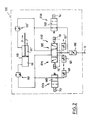
- the reference 1 generally designates the water treatment basin, comprising a filter bed 2 surmounted by a body of water 3 to be treated. Strainers 4 collect the water in the lower part of the filter bed, this treated water being collected by a pipe 5 provided with an adjustable valve 6, for example a butterfly valve.
- a tranquilizer tube 7 containing two electrodes E1, E2 for detecting the water level; these electrodes are identical, and each constitute an "all or nothing" detection system delivering an electrical signal to a control unit 8.
- the electrode E1 is placed at the setpoint level which it is desired to maintain in the basin and which corresponds to the optimal filtration speed, while the electrode E2 is placed slightly above this setpoint level (for example at About 4 cm above it) and serves as an alarm electrode to indicate that the level has been exceeded, for example in the event of a clogging of the filter, no longer allowing regulation by valve 6.
- the control unit 8 is for example constituted by a sequential automaton such as a TELEMECANIQUE TSX 27-20, which receives the signals from the two sensors E1 and E2, and sends control pulses to the relays of two electrovalves EV1 and EV2.
- solenoid valves are part of a pneumatic circuit 100 for controlling the valve, connected to a source of compressed air S and actuating a double-acting jack 110.
- This pneumatic circuit comprises a double-acting cylinder 110 with two chambers 111 (controlling the opening of the valve) and 111 ⁇ (controlling the closing of the valve), each connected by l 'Intermediate flow reducers 112 and 112 ⁇ , to a distributor 120 with three positions constituting the double solenoid valve EV1, EV2.
- the chamber 111 is also connected to a two-position distributor 140 (solenoid valve EV3), and the chamber 111 ⁇ to another two-position distributor 150 (solenoid valve EV4).
- the different distributors are shown in the position they occupy in the absence of any electrical supply from the different control relays Y1, Y2, Y3, Y4.
- the distributor 120 is in the central position, closing off the pipes connected to the chambers 111 and 111 ⁇ .
- the chamber 111 is put in communication by the distributor 140 with the open air by means of an exhaust retarder 141; in the same way, the chamber 111 ⁇ (controlling the closing of the valve) is connected by the distributor 150 to the pressure source S, with the interposition of a pressure regulator filter 130.
- the pneumatic circuit causes the valve to close by pressurizing the chamber 111 ⁇ and venting the chamber 111 as soon as the electrical supply to the installation is interrupted -the valve having to be in closed position when the installation is at rest.
- control solenoids Y3 and Y4 are continuously supplied, which causes the drawers of the distributors 140 and 150 to tip into a position decoupling the chambers 111 and 111 ⁇ from the exhaust regulator 141 and from the pressure regulator 130 at which they were previously linked.
- actuation of Y1 will feed the cylinder in the direction of opening of the valve, by putting in communication the chamber 111 with the pressure regulator 130, and the chamber 111 ⁇ with the exhaust regulator 121 (offset of the distributor valve 120 towards the right in relation to the position illustrated in the figure).
- FIG. 3 illustrates in the form of a flowchart the operation of the control circuit 8.
- the electrode is tested to find out whether it is underwater.
- the EV2 solenoid valve (controlling the closing of valve 6) is opened for a few tenths of a second (for example 100 to 400 ms), then closed; after a duration from 10 to 150 s, the state of the valve and that of the electrode are successively tested, and the operation is repeated (closing of the valve by an additional increment) until the electrode either submerged, or until the valve is completely closed.
- the valve is gradually opened (right part of the flowchart) in the same way as above, that is to say by successive actuations of the solenoid valve EV1 (controlling the opening of the valve 6) followed by a test of the state of the valve and of the state of the electrode, until the latter is dewatered.
- the general algorithm is then reiterated, after a time delay sufficient to avoid the phenomena of "pumping" of the regulation loop; the time delay is chosen so as to be greater than the time constant of the hydraulic system constituted by the filter bed (pressure drop) and the volume of water to be flowed upstream.
Landscapes
- Chemical & Material Sciences (AREA)
- Chemical Kinetics & Catalysis (AREA)
- Filtration Of Liquid (AREA)
Applications Claiming Priority (2)
| Application Number | Priority Date | Filing Date | Title |
|---|---|---|---|
| FR8703656 | 1987-03-17 | ||
| FR8703656A FR2612420B1 (fr) | 1987-03-17 | 1987-03-17 | Procede et installation de regulation de la vitesse de filtration dans un bassin a lit filtrant, notamment pour le traitement des eaux domestiques |
Publications (1)
| Publication Number | Publication Date |
|---|---|
| EP0286477A1 true EP0286477A1 (de) | 1988-10-12 |
Family
ID=9349080
Family Applications (1)
| Application Number | Title | Priority Date | Filing Date |
|---|---|---|---|
| EP88400615A Withdrawn EP0286477A1 (de) | 1987-03-17 | 1988-03-15 | Verfahren und Vorrichtung zur Regulierung der Filtrationsgeschwindigkeit in einem Filterbett, insbesondere bei der Behandlung von Wasser |
Country Status (2)
| Country | Link |
|---|---|
| EP (1) | EP0286477A1 (de) |
| FR (1) | FR2612420B1 (de) |
Citations (4)
| Publication number | Priority date | Publication date | Assignee | Title |
|---|---|---|---|---|
| GB927667A (en) * | 1961-08-30 | 1963-05-29 | Union Tank Car Co | Improvements in monovalve filters |
| FR1483915A (fr) * | 1966-04-26 | 1967-06-09 | Degremont | Dispositif de régulation électrohydraulique pour filtre ouvert |
| EP0072264A1 (de) * | 1981-06-25 | 1983-02-16 | "DEGREMONT" Société dite: | Filter mit angeordnetem körnigem Material |
| EP0150919A2 (de) * | 1984-01-12 | 1985-08-07 | Water Research Centre | Verfahren und Anlage zum Steuern einer Filterrückspülung |
-
1987
- 1987-03-17 FR FR8703656A patent/FR2612420B1/fr not_active Expired - Lifetime
-
1988
- 1988-03-15 EP EP88400615A patent/EP0286477A1/de not_active Withdrawn
Patent Citations (4)
| Publication number | Priority date | Publication date | Assignee | Title |
|---|---|---|---|---|
| GB927667A (en) * | 1961-08-30 | 1963-05-29 | Union Tank Car Co | Improvements in monovalve filters |
| FR1483915A (fr) * | 1966-04-26 | 1967-06-09 | Degremont | Dispositif de régulation électrohydraulique pour filtre ouvert |
| EP0072264A1 (de) * | 1981-06-25 | 1983-02-16 | "DEGREMONT" Société dite: | Filter mit angeordnetem körnigem Material |
| EP0150919A2 (de) * | 1984-01-12 | 1985-08-07 | Water Research Centre | Verfahren und Anlage zum Steuern einer Filterrückspülung |
Also Published As
| Publication number | Publication date |
|---|---|
| FR2612420B1 (fr) | 1990-12-14 |
| FR2612420A1 (fr) | 1988-09-23 |
Similar Documents
| Publication | Publication Date | Title |
|---|---|---|
| KR20020026417A (ko) | 필터의 완전성 테스트시스템을 구비한 물 분배 장치 | |
| EP0121105B1 (de) | Vorrichtung zur Filterung von Flüssigkeiten | |
| EP0820344A1 (de) | Verfahren zum betrieben und steuern einer gruppe von filtrationsmembranemodulen und eine gruppe von modulen zur ausfürung dieses verfahrens | |
| US5049510A (en) | Process for histological tissue specimen treatment that includes variable sensitivity level control | |
| EP1300167A2 (de) | Vorrichtung und Verfahren zur Bestimmung der Alterung eines Flüssigkeitsfilter | |
| FR2474330A1 (fr) | Procede et appareil de filtrage, particulierement pour epurer de grands volumes de fluide | |
| FR2487679A1 (fr) | Rein artificiel - regulation de la pression du liquide de dialyse | |
| JP6585610B2 (ja) | 遠心分離機の排出タイミング制御方法及び遠心分離機 | |
| FR2568137A1 (fr) | Dispositif de filtration de fluide | |
| FR2586202A1 (fr) | Procedes et dispositifs de decolmatage en marche d'un filtre tangentiel | |
| FR2716385A1 (fr) | Procédé et dispositif de rétrolavage de modules de filtration. | |
| US5769539A (en) | Backflush system for a filter membrane located upstream of a hydrocarbon analyzer apparatus | |
| WO1993011845A1 (en) | Automated bubble trap | |
| KR20070096799A (ko) | 역침투 장치 | |
| EP0286477A1 (de) | Verfahren und Vorrichtung zur Regulierung der Filtrationsgeschwindigkeit in einem Filterbett, insbesondere bei der Behandlung von Wasser | |
| FR2473313A1 (fr) | Dispositif de sterilisation d'un liquide | |
| JPH0359345B2 (de) | ||
| KR20070096798A (ko) | 역침투 장치 | |
| FR3031972A1 (fr) | Dispositif de purification d'un liquide pollue | |
| FR2609645A1 (fr) | Installation de filtration modulaire automatique | |
| FR2733698A1 (fr) | Dispositif de mise en pression a actionnement liquide pour une installation de dessalement d'eau de mer ou d'eaux saumatres | |
| FR3031913A1 (fr) | Dispositif de purification d'un liquide comprenant un capteur de mesure de pression | |
| FR2931146A1 (fr) | Procede de controle de l'integrite de membranes de filtration a plaques ou tubes ou de moules membranaires de filtration a plaques ou tubes dans une installation de traitement d'eaux usees | |
| FR2528870A1 (fr) | Dispositif et procede de recuperation du cuivre | |
| EP0084476B1 (de) | Vorrichtung zur Behandlung von Flüssigkeiten mittels Ionenaustauscherharzes, insbesondere Haushaltswasserenthärtungsgerät |
Legal Events
| Date | Code | Title | Description |
|---|---|---|---|
| PUAI | Public reference made under article 153(3) epc to a published international application that has entered the european phase |
Free format text: ORIGINAL CODE: 0009012 |
|
| AK | Designated contracting states |
Kind code of ref document: A1 Designated state(s): AT BE CH DE ES FR GB GR IT LI LU NL SE |
|
| STAA | Information on the status of an ep patent application or granted ep patent |
Free format text: STATUS: THE APPLICATION IS DEEMED TO BE WITHDRAWN |
|
| 18D | Application deemed to be withdrawn |
Effective date: 19890413 |