EP0286484A1 - Verfahren zum Wickeln einer nichtradialen Windung für eine Kathodenstrahlröhrenablenkeinheit - Google Patents
Verfahren zum Wickeln einer nichtradialen Windung für eine Kathodenstrahlröhrenablenkeinheit Download PDFInfo
- Publication number
- EP0286484A1 EP0286484A1 EP88400650A EP88400650A EP0286484A1 EP 0286484 A1 EP0286484 A1 EP 0286484A1 EP 88400650 A EP88400650 A EP 88400650A EP 88400650 A EP88400650 A EP 88400650A EP 0286484 A1 EP0286484 A1 EP 0286484A1
- Authority
- EP
- European Patent Office
- Prior art keywords
- winding
- layer
- radial
- pitch
- turns
- Prior art date
- Legal status (The legal status is an assumption and is not a legal conclusion. Google has not performed a legal analysis and makes no representation as to the accuracy of the status listed.)
- Granted
Links
- 238000004804 winding Methods 0.000 title claims abstract description 60
- 238000000034 method Methods 0.000 title claims description 19
- 239000000853 adhesive Substances 0.000 abstract description 7
- 230000001070 adhesive effect Effects 0.000 abstract description 7
- 229910000859 α-Fe Inorganic materials 0.000 description 31
- 238000012937 correction Methods 0.000 description 3
- 201000009310 astigmatism Diseases 0.000 description 2
- 238000000151 deposition Methods 0.000 description 2
- 238000009826 distribution Methods 0.000 description 2
- 238000004519 manufacturing process Methods 0.000 description 2
- 239000002390 adhesive tape Substances 0.000 description 1
- 230000000694 effects Effects 0.000 description 1
- 238000010894 electron beam technology Methods 0.000 description 1
- 230000005294 ferromagnetic effect Effects 0.000 description 1
- 239000003292 glue Substances 0.000 description 1
- 230000005291 magnetic effect Effects 0.000 description 1
- 239000000463 material Substances 0.000 description 1
- 230000002093 peripheral effect Effects 0.000 description 1
- 238000000926 separation method Methods 0.000 description 1
- 239000001993 wax Substances 0.000 description 1
Images
Classifications
-
- H—ELECTRICITY
- H01—ELECTRIC ELEMENTS
- H01J—ELECTRIC DISCHARGE TUBES OR DISCHARGE LAMPS
- H01J29/00—Details of cathode-ray tubes or of electron-beam tubes of the types covered by group H01J31/00
- H01J29/46—Arrangements of electrodes and associated parts for generating or controlling the ray or beam, e.g. electron-optical arrangement
- H01J29/70—Arrangements for deflecting ray or beam
- H01J29/72—Arrangements for deflecting ray or beam along one straight line or along two perpendicular straight lines
- H01J29/76—Deflecting by magnetic fields only
-
- H—ELECTRICITY
- H01—ELECTRIC ELEMENTS
- H01J—ELECTRIC DISCHARGE TUBES OR DISCHARGE LAMPS
- H01J9/00—Apparatus or processes specially adapted for the manufacture, installation, removal, maintenance of electric discharge tubes, discharge lamps, or parts thereof; Recovery of material from discharge tubes or lamps
- H01J9/236—Manufacture of magnetic deflecting devices for cathode-ray tubes
-
- H—ELECTRICITY
- H01—ELECTRIC ELEMENTS
- H01J—ELECTRIC DISCHARGE TUBES OR DISCHARGE LAMPS
- H01J2209/00—Apparatus and processes for manufacture of discharge tubes
- H01J2209/236—Manufacture of magnetic deflecting devices
- H01J2209/2363—Coils
- H01J2209/2366—Machines therefor, e.g. winding, forming, welding, or the like
-
- Y—GENERAL TAGGING OF NEW TECHNOLOGICAL DEVELOPMENTS; GENERAL TAGGING OF CROSS-SECTIONAL TECHNOLOGIES SPANNING OVER SEVERAL SECTIONS OF THE IPC; TECHNICAL SUBJECTS COVERED BY FORMER USPC CROSS-REFERENCE ART COLLECTIONS [XRACs] AND DIGESTS
- Y10—TECHNICAL SUBJECTS COVERED BY FORMER USPC
- Y10T—TECHNICAL SUBJECTS COVERED BY FORMER US CLASSIFICATION
- Y10T29/00—Metal working
- Y10T29/49—Method of mechanical manufacture
- Y10T29/49002—Electrical device making
- Y10T29/4902—Electromagnet, transformer or inductor
- Y10T29/49071—Electromagnet, transformer or inductor by winding or coiling
Definitions
- the invention relates to a winding method for non-radial winding of a cathode ray tube deflector.
- Trichrome cathode ray tubes in line with barrels are currently equipped with deflectors themselves realizing the auto-convergence of the electron beams and the corrections of image geometry.
- the line field, created by saddle-shaped coils, is said to be “positive astigmatism", while the field field is said to be “negative mean astigmastime” to ensure convergence and to “positive forward astigmatism” to ensure geometry correction.
- a saddle-shaped coil or a toroidal coil can be used.
- the toroidal coil can be produced either with a radial frame cooperating with field conformers (ferromagnetic parts attached to the deflector), or by using an inclined winding technique with a rear angle greater than the front angle, such winding being able to also be associated with magnetic correction means.
- the latter solution widely used, generally uses one of the following three techniques for winding: - Plastic parts are used provided with notches fixed at the front and at the rear of the ferrite, these notches determining the inclination of the winding wire.
- the subject of the present invention is a winding method making it possible to obtain winding wire inclinations of up to approximately 30 ° on the edges of the winding, on bare ferrites without notches, without the addition of parts or of adhesive element. , a process that can be easily automated.
- the method according to the invention consists in producing a first winding layer at least approximately radially with a large winding pitch, then in depositing the following non-radial layers using at least part of the wires of the first layer to avoid the sliding of the following layers.
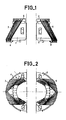
- FIGS. 1 and 2 show exploded front and rear views of the two half-ferrites 1,2 each comprising a half-frame winding 3,4.
- the wires of the half-windings 3,4 are not arranged radially, that is to say that they are not parallel to the generatrices of the conical surface formed by the half-ferrites 1,2. These wires form with respect to these generators a variable angle of inclination according to the position of the strands of wire within the winding and as a function of the angular position of the notches.
- plastic parts with notches 5,6 and 7,8 are fixed on the front and rear end faces of each half-ferrite 1,2.
- the successive turns of the half-windings 3,4 are maintained by these notches, which allows them to be wound with a high angle of inclination.
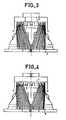
- FIGS. 3,4 show two side views, considered at 180 ° relative to each other, of a finished deflector, produced from the elements of FIGS. 1 and 2.
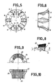
- FIGS. 5 and 6 show another embodiment of a deflector of the prior art.
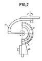
- the winding machine essentially comprises a device 20 for holding and driving in rotation the half-ferrites 21, and a rotary wire guide 22 (better known under the English name of "flyer"), the axis of rotation 23 of which is perpendicular to the axis B of the half-ferrites 21 in the radial winding position.
- FIG. 7 shows a half-ferrite 21 on which the wire guide 22 is depositing the layer of radial winding 24 at large pitch.
- the turns of this first layer being substantially radial (that is to say truly radial or inclined by a few degrees), have a stable positioning relative to the portion of conical crown formed by the half-ferrite whose generator is also radial . These turns will be difficult to move when removing the following non-radial layers (or at least for the second layer which guides the following) for which they act as retaining notches.
- the radial winding and the non-radial winding are carried out with the same wire, without interruption.
- the pitch (angle of rotation of the ferrite or of the "flyer" around the axis B for a turn) of this first layer 24 is constant and equal to approximately 2 to 5 times the pitch of a winding with contiguous turns made with the same wire.
- this pitch is variable: it has a first value P1 at the ends of the layer, and a second value P2, greater than P1, in the middle of the layer.
- P1 is equal to approximately 2 to 5 times said pitch of winding with contiguous turns
- P2 is equal to approximately 2 to 3 times P1.
- the layer 24 must be sufficiently wide, in particular at the rear of the ferrite and protrudes slightly at the front (from 5 turns approximately) of the following layers, in order to be sure that the extreme turns of the non-radial winding will always be maintained by those of the layer 24 without the need to position with great precision the first turn of the non-radial winding 25 , compared to layer 24.
- the half-ferrite 21 is inclined around an axis contained in the break plane P (the plane of separation between two half-ferrites formed by breaking of an entire ferrite) .
- the trace T of this axis (which is perpendicular to the plane of the drawing).
- B be the machine axis (axis around which the machine rotates the half-ferrites to make the radial windings).
- the angle I formed by B and P is the angle of inclination of the ferrite.
- the angles of inclination of the different turns of the non-radial winding 25 depend on the angle I and on the angular position of these turns within the winding.
- the angular distribution of the different turns of the resulting winding (24 + 25) is the composition of the distribution of the different layers, the effect of the first one being weak insofar as its number of turns is low.
- the winding pitch of the non-radial layers is greater than that which would have been without the first radial layer, so as to allow the wires of this first layer to be interposed in the turns of the subsequent layers of the winding without disturbing the arrangement too much.
- the process of the present invention can be implemented when it is desired to obtain a winding whose coverage angle (angle at the center formed by the two extreme turns of the winding, in a plane PA perpendicular to the axis of the ferrite ) front is greater than the rear coverage angle (that is to say for a plane PA passing through the front or rear front face, respectively of the ferrite), and this, with a first radial layer (like said layer 24). After having wound the first layer, the half-ferrite is tilted in a direction opposite to that shown in FIG. 8.
- This type of winding is useful in particular for producing a self-converging deflector giving an image having good resolution uniformity.
Landscapes
- Engineering & Computer Science (AREA)
- Manufacturing & Machinery (AREA)
- Coils Or Transformers For Communication (AREA)
- Formation Of Various Coating Films On Cathode Ray Tubes And Lamps (AREA)
- Coil Winding Methods And Apparatuses (AREA)
Applications Claiming Priority (2)
| Application Number | Priority Date | Filing Date | Title |
|---|---|---|---|
| FR8703992 | 1987-03-23 | ||
| FR8703992A FR2613128B1 (fr) | 1987-03-23 | 1987-03-23 | Procede de bobinage pour bobinage non radial de deviateur de tube cathodique |
Publications (2)
| Publication Number | Publication Date |
|---|---|
| EP0286484A1 true EP0286484A1 (de) | 1988-10-12 |
| EP0286484B1 EP0286484B1 (de) | 1993-09-15 |
Family
ID=9349304
Family Applications (1)
| Application Number | Title | Priority Date | Filing Date |
|---|---|---|---|
| EP88400650A Expired - Lifetime EP0286484B1 (de) | 1987-03-23 | 1988-03-18 | Verfahren zum Wickeln einer nichtradialen Windung für eine Kathodenstrahlröhrenablenkeinheit |
Country Status (7)
| Country | Link |
|---|---|
| US (1) | US5165614A (de) |
| EP (1) | EP0286484B1 (de) |
| JP (1) | JP2950828B2 (de) |
| KR (1) | KR960008603B1 (de) |
| CN (2) | CN1020059C (de) |
| DE (1) | DE3884035T2 (de) |
| FR (1) | FR2613128B1 (de) |
Families Citing this family (8)
| Publication number | Priority date | Publication date | Assignee | Title |
|---|---|---|---|---|
| FR2942980B1 (fr) * | 2009-03-13 | 2011-04-08 | Amada Europ | Presse plieuse pour le pliage de feuilles |
| US9185974B2 (en) | 2010-06-02 | 2015-11-17 | Steelcase Inc. | Frame type workstation configurations |
| US9210999B2 (en) | 2010-06-02 | 2015-12-15 | Steelcase Inc. | Frame type table assemblies |
| US8689705B2 (en) | 2010-06-02 | 2014-04-08 | Steelcase, Inc. | Reconfigurable table assemblies |
| US8667908B2 (en) | 2010-06-02 | 2014-03-11 | Steelcase Inc. | Frame type table assemblies |
| US12376677B1 (en) | 2012-10-10 | 2025-08-05 | Steelcase Inc. | Ergonomic seating system, tilt-lock control and remote powering method and apparatus |
| WO2017197395A1 (en) | 2016-05-13 | 2017-11-16 | Steelcase Inc. | Multi-tiered workstation assembly |
| US10517392B2 (en) | 2016-05-13 | 2019-12-31 | Steelcase Inc. | Multi-tiered workstation assembly |
Citations (2)
| Publication number | Priority date | Publication date | Assignee | Title |
|---|---|---|---|---|
| EP0039276A1 (de) * | 1980-04-22 | 1981-11-04 | Videocolor | Verfahren zum Wickeln von mehreren Drahtverbindungen auf einen Kern, insbes. zum Bewickeln von Ablenkringen für Kathodenstrahlröhren, Maschinen zur Durchfürung des Verfahrens und mit Hilfe des Verfahrens erzeugte Wicklung |
| FR2549639A1 (fr) * | 1983-07-18 | 1985-01-25 | Rca Corp | Bobines modifiees de deviation et procede de formation |
Family Cites Families (4)
| Publication number | Priority date | Publication date | Assignee | Title |
|---|---|---|---|---|
| US2757073A (en) * | 1953-03-31 | 1956-07-31 | Du Pont | Process for making pulverulent silica powder |
| US3299379A (en) * | 1962-10-22 | 1967-01-17 | Muter Company | Deflection yoke |
| JPS58133744A (ja) * | 1982-02-03 | 1983-08-09 | Mitsubishi Electric Corp | トロイダル形偏向コイルの製造方法 |
| US4469285A (en) * | 1982-09-01 | 1984-09-04 | Universal Manufacturing Co., Inc. | Coil winding machine with multi-axis positioning for winding television deflection coils |
-
1987
- 1987-03-23 FR FR8703992A patent/FR2613128B1/fr not_active Expired
-
1988
- 1988-01-19 CN CN88100317A patent/CN1020059C/zh not_active Expired - Fee Related
- 1988-03-18 EP EP88400650A patent/EP0286484B1/de not_active Expired - Lifetime
- 1988-03-18 DE DE88400650T patent/DE3884035T2/de not_active Expired - Fee Related
- 1988-03-21 KR KR1019880002983A patent/KR960008603B1/ko not_active Expired - Fee Related
- 1988-03-23 JP JP63069221A patent/JP2950828B2/ja not_active Expired - Fee Related
-
1991
- 1991-07-01 US US07/724,434 patent/US5165614A/en not_active Expired - Lifetime
-
1992
- 1992-05-29 CN CN92104242A patent/CN1021714C/zh not_active Expired - Fee Related
Patent Citations (2)
| Publication number | Priority date | Publication date | Assignee | Title |
|---|---|---|---|---|
| EP0039276A1 (de) * | 1980-04-22 | 1981-11-04 | Videocolor | Verfahren zum Wickeln von mehreren Drahtverbindungen auf einen Kern, insbes. zum Bewickeln von Ablenkringen für Kathodenstrahlröhren, Maschinen zur Durchfürung des Verfahrens und mit Hilfe des Verfahrens erzeugte Wicklung |
| FR2549639A1 (fr) * | 1983-07-18 | 1985-01-25 | Rca Corp | Bobines modifiees de deviation et procede de formation |
Non-Patent Citations (1)
| Title |
|---|
| PATENT ABSTRACTS OF JAPAN, vol. 7, no. 247 (E-208)[1392], 2 novembre 1983; & JP-A-58 133 744 (MITSUBISHI DENKI K.K.) 09-08-1983 * |
Also Published As
| Publication number | Publication date |
|---|---|
| DE3884035T2 (de) | 1994-02-24 |
| JP2950828B2 (ja) | 1999-09-20 |
| CN88100317A (zh) | 1988-10-05 |
| CN1067137A (zh) | 1992-12-16 |
| CN1020059C (zh) | 1993-03-10 |
| FR2613128A1 (fr) | 1988-09-30 |
| KR880011874A (ko) | 1988-10-31 |
| DE3884035D1 (de) | 1993-10-21 |
| EP0286484B1 (de) | 1993-09-15 |
| JPS6471033A (en) | 1989-03-16 |
| KR960008603B1 (ko) | 1996-06-28 |
| CN1021714C (zh) | 1993-07-28 |
| US5165614A (en) | 1992-11-24 |
| FR2613128B1 (fr) | 1989-05-26 |
Similar Documents
| Publication | Publication Date | Title |
|---|---|---|
| CA2071157C (fr) | Procede pour l'enroulement d'un bobinage electrique | |
| EP0286484B1 (de) | Verfahren zum Wickeln einer nichtradialen Windung für eine Kathodenstrahlröhrenablenkeinheit | |
| FR2536052A1 (fr) | Procede et appareil pour l'enroulement d'un materiau flexible et enroulements ainsi obtenus | |
| EP0389360B1 (de) | Spule mit einer sehr langen optischen Glasfaser für eine mit einem Draht gesteuerte Rakete | |
| FR2519175A1 (fr) | Unite de tete rotative | |
| EP0174215A1 (de) | Vorrichtung zum Einführen von optischen Fibern | |
| FR2652572A1 (fr) | Procede d'enroulement en double d'un cable ou analogue sur la surface externe d'un touret. | |
| EP0211387B1 (de) | Vorrichtung und Verfahren zum Vereinigen von Fäden, Fäden, die mit dieser Vorrichtung und nach diesem Verfahren hergestellt sind | |
| FR2480802A1 (fr) | Dispositif de broche a double torsion | |
| EP0214897A1 (de) | Herstellungsverfahren für eine torusförmige Wicklung mit kleinen Ausmassen und optimaler Geometrie | |
| FR2833746A1 (fr) | Procede de fabrication en continu d'un cable coaxial annele | |
| EP4125193A1 (de) | Automatische drahtwickelmaschine mit abstufung für mehrpoligen rotor | |
| EP0728117B1 (de) | Verfahren zur versetzten anordnung der lagen einer wicklung | |
| FR2688495A1 (fr) | Machine de debobinage a departs de fil multiples sur une meme bobine. | |
| EP0693670B1 (de) | Vorrichtung zum Markierung der Länge von Fasern auf einer faseroptischen Spule, und Verfahren zu deren Herstellung | |
| EP3793815B1 (de) | Anlage und verfahren zum sortieren von wultskernen für reifen mit kontrolle des azimuts | |
| FR2757996A1 (fr) | Transformateur haute tension a enroulements en vrac ranges | |
| FR2681149A1 (fr) | Dispositif d'insertion de rubans a fibres optiques dans les rainures helicouidales d'un jonc rainure. | |
| WO2020128368A1 (fr) | Outil de repartition pour module de guipage | |
| EP0802543A1 (de) | Vierer mit ein Metallband zum Festhalten | |
| FR2762022A1 (fr) | Broche pour le retordage ou le cablage de fils | |
| FR2641772A1 (fr) | Procede et dispositif perfectionnes d'enroulement de fil et bobine croisee obtenue | |
| BE510804A (de) | ||
| WO2026052922A1 (fr) | Enroulement d'une gaine en matière plastique, procédé de fabrication d'un tel enroulement et système de fabrication pour la mise en oeuvre du procédé | |
| FR2535891A1 (fr) | Conducteur electrique constitue en fils nus assembles |
Legal Events
| Date | Code | Title | Description |
|---|---|---|---|
| PUAI | Public reference made under article 153(3) epc to a published international application that has entered the european phase |
Free format text: ORIGINAL CODE: 0009012 |
|
| AK | Designated contracting states |
Kind code of ref document: A1 Designated state(s): DE GB IT NL |
|
| 17P | Request for examination filed |
Effective date: 19890328 |
|
| 17Q | First examination report despatched |
Effective date: 19910905 |
|
| GRAA | (expected) grant |
Free format text: ORIGINAL CODE: 0009210 |
|
| RAP1 | Party data changed (applicant data changed or rights of an application transferred) |
Owner name: THOMSON TUBES & DISPLAYS SA |
|
| AK | Designated contracting states |
Kind code of ref document: B1 Designated state(s): DE GB IT NL |
|
| PG25 | Lapsed in a contracting state [announced via postgrant information from national office to epo] |
Ref country code: NL Effective date: 19930915 |
|
| REF | Corresponds to: |
Ref document number: 3884035 Country of ref document: DE Date of ref document: 19931021 |
|
| ITF | It: translation for a ep patent filed | ||
| GBT | Gb: translation of ep patent filed (gb section 77(6)(a)/1977) |
Effective date: 19931112 |
|
| NLV1 | Nl: lapsed or annulled due to failure to fulfill the requirements of art. 29p and 29m of the patents act | ||
| PLBE | No opposition filed within time limit |
Free format text: ORIGINAL CODE: 0009261 |
|
| STAA | Information on the status of an ep patent application or granted ep patent |
Free format text: STATUS: NO OPPOSITION FILED WITHIN TIME LIMIT |
|
| 26N | No opposition filed | ||
| REG | Reference to a national code |
Ref country code: GB Ref legal event code: 746 Effective date: 20010830 |
|
| REG | Reference to a national code |
Ref country code: GB Ref legal event code: IF02 |
|
| PGFP | Annual fee paid to national office [announced via postgrant information from national office to epo] |
Ref country code: GB Payment date: 20060123 Year of fee payment: 19 |
|
| PGFP | Annual fee paid to national office [announced via postgrant information from national office to epo] |
Ref country code: DE Payment date: 20060322 Year of fee payment: 19 |
|
| PGFP | Annual fee paid to national office [announced via postgrant information from national office to epo] |
Ref country code: IT Payment date: 20060331 Year of fee payment: 19 |
|
| GBPC | Gb: european patent ceased through non-payment of renewal fee |
Effective date: 20070318 |
|
| PG25 | Lapsed in a contracting state [announced via postgrant information from national office to epo] |
Ref country code: DE Free format text: LAPSE BECAUSE OF NON-PAYMENT OF DUE FEES Effective date: 20071002 |
|
| PG25 | Lapsed in a contracting state [announced via postgrant information from national office to epo] |
Ref country code: GB Free format text: LAPSE BECAUSE OF NON-PAYMENT OF DUE FEES Effective date: 20070318 |
|
| PG25 | Lapsed in a contracting state [announced via postgrant information from national office to epo] |
Ref country code: IT Free format text: LAPSE BECAUSE OF NON-PAYMENT OF DUE FEES Effective date: 20070318 |