EP0286573A2 - Clapet de non-retour pour fluide pollué liquide ou gazeux - Google Patents
Clapet de non-retour pour fluide pollué liquide ou gazeux Download PDFInfo
- Publication number
- EP0286573A2 EP0286573A2 EP88710005A EP88710005A EP0286573A2 EP 0286573 A2 EP0286573 A2 EP 0286573A2 EP 88710005 A EP88710005 A EP 88710005A EP 88710005 A EP88710005 A EP 88710005A EP 0286573 A2 EP0286573 A2 EP 0286573A2
- Authority
- EP
- European Patent Office
- Prior art keywords
- partition
- sealing element
- openings
- check valve
- valve
- Prior art date
- Legal status (The legal status is an assumption and is not a legal conclusion. Google has not performed a legal analysis and makes no representation as to the accuracy of the status listed.)
- Withdrawn
Links
Images
Classifications
-
- F—MECHANICAL ENGINEERING; LIGHTING; HEATING; WEAPONS; BLASTING
- F16—ENGINEERING ELEMENTS AND UNITS; GENERAL MEASURES FOR PRODUCING AND MAINTAINING EFFECTIVE FUNCTIONING OF MACHINES OR INSTALLATIONS; THERMAL INSULATION IN GENERAL
- F16K—VALVES; TAPS; COCKS; ACTUATING-FLOATS; DEVICES FOR VENTING OR AERATING
- F16K15/00—Check valves
- F16K15/14—Check valves with flexible valve members
Definitions
- Check valves generally have the task of allowing the direction of flow of a medium in a pipe or the like in only one direction. This is intended, for example, to prevent the pumped medium from flowing back, for example in the event of a sudden drop in pressure in the pipeline, and from transporting undesired constituents in the wrong direction.
- the task of a check valve can be to supply liquid or gaseous additives to a medium in a container or in a pipeline through a further pipeline at higher pressure if required. It must be ensured that, for. B. in the event of an interruption in the supply, if the pressure in the metering line is lower than that in the container or in the mixing line, backflow of the medium supplied with the additives is prevented. This means that the container or the mixing line must be closed securely and quickly with respect to the metering line, the internal pressure generally supplying the energy required for the closing of the check valve.
- check valves can, for example, prevent toxic gas or liquids from escaping to the outside or into a pipeline system in the event of an unforeseen loss of pressure, and pose incalculable dangers to the environment. In other cases, it can be of considerable economic importance to prevent the backflow of contaminated media if this could destroy expensive devices and machines.
- the required tasks can be covered with sufficient certainty by commercially available check valves.
- a more or less elastic circular disk is normally pressed by the container or pipeline pressure against a smaller opening provided with a raised edge, whereby this is closed.
- the elasti cal disc can be made of rubber, for example. To prevent it from deforming due to the pressure acting and no longer closes securely, it is pressure-side with another disk made of rigid material, for. B. brass provided. This ensures that the sealing element rests at all points on the sealing edge without bending or bending.
- a valve disk designed in this way also requires a guide which ensures that it only moves normally to the closing plane and cannot be moved laterally. This is achieved, for example, in that the brass disk has a central pin which is movable in the longitudinal direction in a bore. A compression coil spring is also placed on the pin between the disc and the bore, which presses the valve disk against the valve seat. This ensures that the valve disc is securely positioned on the valve seat even when the tank or pipeline is depressurized.
- Valves of this type have the disadvantage, on the one hand, that production is relatively expensive. On the other hand, after some time, the sealing element tends to harden in the area of the annular sealing point, which leads to leaks. Too soft elements would have the disadvantage of yielding too much to the contact pressure, so that the required tightness would also not be guaranteed.
- the object of the present invention is now to avoid these disadvantages. This is achieved primarily by using a highly elastic sealing element which seals over a large area and also seals securely even when there are dirt particles between the sealing surface and the sealing element and is not damaged on the surface. Furthermore, the elasticity of the sealing material is sufficient to close the flow openings even in the unpressurized state, without additional external forces having to be applied, for example by a helical spring. This is achieved by deforming and prestressing the sealing element against the passage openings so that it seals due to its own elasticity.
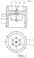
- a generally round valve body 1 has a partition 2 across the flow of the flowing medium, which with openings, for. B. holes 3 is provided.
- the partition 2 is level on one side and tapered on the other side towards the center.
- On this hollow side there is an elastic sealing element 4, for example made of rubber, the diameter of which is larger than the outermost limit of the openings.
- an elastic sealing element 4 for example made of rubber, the diameter of which is larger than the outermost limit of the openings.
- a screw 5 with which the sealing element is held in the center of the openings.
- the screw also has the task of compressing the sealing element 4 in the middle by means of a nut 6 and washer 7, so that a more or less inwardly lowered end face is produced.
- the screw 5 is fastened in the middle bore of the partition 2 with the nut 8 so that no more movement is possible, and the sealing element 4 is biased against the partition 2.
- valve from the side of the partition 2 If the valve from the side of the partition 2 is pressurized with a liquid or gaseous medium under a certain pressure, it can flow through the openings 3 in the partition 2, since the sealing element 4 yields on the outer edge due to its elastic property and Flow with relatively low resistance releases Prerequisite for this is that the pressure on the side of the sealing element 4 is lower than on the side of the partition 2. On the other hand, the sealing element is able to close the valve tightly in the opposite direction if there are opposite pressure conditions .
- the valve also closes tightly when dirt particles settle between the sealing element 4 and the partition 2, since the elastic material can deform sufficiently.
Landscapes
- Engineering & Computer Science (AREA)
- General Engineering & Computer Science (AREA)
- Mechanical Engineering (AREA)
- Check Valves (AREA)
Applications Claiming Priority (2)
| Application Number | Priority Date | Filing Date | Title |
|---|---|---|---|
| DE8705153U | 1987-04-07 | ||
| DE8705153U DE8705153U1 (de) | 1987-04-07 | 1987-04-07 | Rückschlagventil für verschmutzte Medien |
Publications (2)
| Publication Number | Publication Date |
|---|---|
| EP0286573A2 true EP0286573A2 (fr) | 1988-10-12 |
| EP0286573A3 EP0286573A3 (fr) | 1989-03-29 |
Family
ID=6806798
Family Applications (1)
| Application Number | Title | Priority Date | Filing Date |
|---|---|---|---|
| EP88710005A Withdrawn EP0286573A3 (fr) | 1987-04-07 | 1988-04-07 | Clapet de non-retour pour fluide pollué liquide ou gazeux |
Country Status (2)
| Country | Link |
|---|---|
| EP (1) | EP0286573A3 (fr) |
| DE (1) | DE8705153U1 (fr) |
Cited By (1)
| Publication number | Priority date | Publication date | Assignee | Title |
|---|---|---|---|---|
| EP0531234A1 (fr) * | 1991-09-05 | 1993-03-10 | KIS PHOTO INDUSTRIE S.a.r.l. | Dispositif pour compenser automatiquement l'évaporation des bains de traitement chimique |
Families Citing this family (2)
| Publication number | Priority date | Publication date | Assignee | Title |
|---|---|---|---|---|
| DE19955886A1 (de) * | 1999-11-20 | 2001-05-23 | Bosch Gmbh Robert | Magnetventil mit einem Rückschlagventil |
| CN103775687B (zh) * | 2014-01-28 | 2016-10-26 | 南通市红星空压机配件制造有限公司 | 一种压力单向阀结构 |
Family Cites Families (3)
| Publication number | Priority date | Publication date | Assignee | Title |
|---|---|---|---|---|
| FR1537110A (fr) * | 1967-07-11 | 1968-08-23 | Perfectionnement aux clapets d'appareils hydrauliques, en particulier d'amortisseurset autres organes de suspension | |
| DE6602486U (de) * | 1967-07-21 | 1969-06-12 | Loctite Technik Gmbh & Co Kg | Manschettenventil |
| FR2291428A1 (fr) * | 1974-11-15 | 1976-06-11 | Chaudronnerie Indle Et Agricol | Clapet antiretour |
-
1987
- 1987-04-07 DE DE8705153U patent/DE8705153U1/de not_active Expired
-
1988
- 1988-04-07 EP EP88710005A patent/EP0286573A3/fr not_active Withdrawn
Cited By (1)
| Publication number | Priority date | Publication date | Assignee | Title |
|---|---|---|---|---|
| EP0531234A1 (fr) * | 1991-09-05 | 1993-03-10 | KIS PHOTO INDUSTRIE S.a.r.l. | Dispositif pour compenser automatiquement l'évaporation des bains de traitement chimique |
Also Published As
| Publication number | Publication date |
|---|---|
| EP0286573A3 (fr) | 1989-03-29 |
| DE8705153U1 (de) | 1987-06-04 |
Similar Documents
| Publication | Publication Date | Title |
|---|---|---|
| EP0271765B1 (fr) | Soupape commandée par le fluide propre, déclenchable notamment par un électroaimant pilote | |
| DE69423879T2 (de) | Plattenventil | |
| DE2217543A1 (de) | Rückschlagventil | |
| WO2017174740A1 (fr) | Vanne à ouverture rapide destinée à un réservoir de fluide d'extinction soumis à une pression et réservoir de fluide d'extinction muni de ladite vanne | |
| DE2404174C3 (fr) | ||
| DE4321787C2 (de) | Kugelrückschlagventil | |
| DE3333518A1 (de) | Dreiwege-kugelhahn | |
| DE60117387T2 (de) | Durchflussbegrenzungsventil | |
| DE102020124511A1 (de) | Durchflussbegrenzer für ein Kraftstoffeinspritzsystem sowie Kraftstoffeinspritzsystem mit einem Durchflussbegrenzer | |
| DE8705153U1 (de) | Rückschlagventil für verschmutzte Medien | |
| DE1550468B2 (de) | Doppelsitzventil | |
| DE2206561A1 (de) | Ventil | |
| DE3707192A1 (de) | Sicherheitsarmatur | |
| DE9108326U1 (de) | Drosselventil zur Regelung abgezweigter Flüssigkeiten | |
| AT326438B (de) | Ventildichtung | |
| DE1550468C3 (de) | Doppelsitzventil | |
| DE3303877A1 (de) | Einzelstempelventil | |
| EP1855014B1 (fr) | Soupape de remplissage | |
| DE102019133996A1 (de) | Ventil | |
| DE202022106308U1 (de) | Rückschlagventil | |
| DE102020130440A1 (de) | Überdrucksicherung zur Begrenzung des Drucks eines Fluids | |
| DE1045201B (de) | Rohr- bzw. Schlauchbruchventil | |
| DE3010905A1 (de) | Rueckschlagventil | |
| DE2439793A1 (de) | Durchlass- und rueckschlagventil | |
| CH367367A (de) | Ventil zum Regulieren von Durchflussmengen, insbesondere für Wasserleitungen |
Legal Events
| Date | Code | Title | Description |
|---|---|---|---|
| PUAI | Public reference made under article 153(3) epc to a published international application that has entered the european phase |
Free format text: ORIGINAL CODE: 0009012 |
|
| AK | Designated contracting states |
Kind code of ref document: A2 Designated state(s): AT BE CH DE ES FR GB GR IT LI LU NL SE |
|
| PUAL | Search report despatched |
Free format text: ORIGINAL CODE: 0009013 |
|
| AK | Designated contracting states |
Kind code of ref document: A3 Designated state(s): AT BE CH DE ES FR GB GR IT LI LU NL SE |
|
| STAA | Information on the status of an ep patent application or granted ep patent |
Free format text: STATUS: THE APPLICATION IS DEEMED TO BE WITHDRAWN |
|
| 18D | Application deemed to be withdrawn |
Effective date: 19890930 |