EP0286598A2 - Opto-elektronische Anordnung zur Bestimmung von Richtung und Geschwindigkeit eines Fahrzeuges mittels Laserstrahlung und gleichzeitige Messung der Rotation - Google Patents
Opto-elektronische Anordnung zur Bestimmung von Richtung und Geschwindigkeit eines Fahrzeuges mittels Laserstrahlung und gleichzeitige Messung der Rotation Download PDFInfo
- Publication number
- EP0286598A2 EP0286598A2 EP88830010A EP88830010A EP0286598A2 EP 0286598 A2 EP0286598 A2 EP 0286598A2 EP 88830010 A EP88830010 A EP 88830010A EP 88830010 A EP88830010 A EP 88830010A EP 0286598 A2 EP0286598 A2 EP 0286598A2
- Authority
- EP
- European Patent Office
- Prior art keywords
- light
- speed
- invention defined
- fact
- laser
- Prior art date
- Legal status (The legal status is an assumption and is not a legal conclusion. Google has not performed a legal analysis and makes no representation as to the accuracy of the status listed.)
- Withdrawn
Links
- 238000005259 measurement Methods 0.000 title claims abstract description 24
- 230000005693 optoelectronics Effects 0.000 title 1
- 230000003287 optical effect Effects 0.000 claims abstract description 30
- 230000033001 locomotion Effects 0.000 claims abstract description 23
- 230000006872 improvement Effects 0.000 claims abstract description 16
- 230000003068 static effect Effects 0.000 claims abstract description 5
- 238000001514 detection method Methods 0.000 claims abstract description 3
- 239000003981 vehicle Substances 0.000 claims description 10
- 239000007787 solid Substances 0.000 claims description 6
- 239000007788 liquid Substances 0.000 claims description 5
- 239000013078 crystal Substances 0.000 claims description 4
- 230000010355 oscillation Effects 0.000 claims description 3
- 239000004065 semiconductor Substances 0.000 claims description 2
- 230000009466 transformation Effects 0.000 claims description 2
- 238000006073 displacement reaction Methods 0.000 claims 1
- 238000009740 moulding (composite fabrication) Methods 0.000 claims 1
- 230000000737 periodic effect Effects 0.000 claims 1
- 230000002226 simultaneous effect Effects 0.000 claims 1
- 230000004048 modification Effects 0.000 abstract description 8
- 238000012986 modification Methods 0.000 abstract description 8
- 238000010586 diagram Methods 0.000 abstract description 5
- 230000008859 change Effects 0.000 abstract description 3
- 230000008602 contraction Effects 0.000 abstract description 2
- 238000004364 calculation method Methods 0.000 description 6
- 230000000694 effects Effects 0.000 description 5
- 239000000463 material Substances 0.000 description 4
- 238000000034 method Methods 0.000 description 3
- 230000009467 reduction Effects 0.000 description 3
- 238000006722 reduction reaction Methods 0.000 description 3
- 230000003993 interaction Effects 0.000 description 2
- 230000035515 penetration Effects 0.000 description 2
- 238000012545 processing Methods 0.000 description 2
- 239000012780 transparent material Substances 0.000 description 2
- 238000004458 analytical method Methods 0.000 description 1
- 230000008901 benefit Effects 0.000 description 1
- 230000027455 binding Effects 0.000 description 1
- 238000009739 binding Methods 0.000 description 1
- 230000015572 biosynthetic process Effects 0.000 description 1
- 230000002844 continuous effect Effects 0.000 description 1
- 238000013480 data collection Methods 0.000 description 1
- 239000005357 flat glass Substances 0.000 description 1
- 239000011521 glass Substances 0.000 description 1
- 230000005484 gravity Effects 0.000 description 1
- 230000001795 light effect Effects 0.000 description 1
- 230000008569 process Effects 0.000 description 1
- 230000000644 propagated effect Effects 0.000 description 1
- 230000001105 regulatory effect Effects 0.000 description 1
- 230000035945 sensitivity Effects 0.000 description 1
- 238000000926 separation method Methods 0.000 description 1
- 230000001360 synchronised effect Effects 0.000 description 1
- 238000012795 verification Methods 0.000 description 1
Images


Classifications
-
- G—PHYSICS
- G01—MEASURING; TESTING
- G01P—MEASURING LINEAR OR ANGULAR SPEED, ACCELERATION, DECELERATION, OR SHOCK; INDICATING PRESENCE, ABSENCE, OR DIRECTION, OF MOVEMENT
- G01P3/00—Measuring linear or angular speed; Measuring differences of linear or angular speeds
- G01P3/42—Devices characterised by the use of electric or magnetic means
- G01P3/50—Devices characterised by the use of electric or magnetic means for measuring linear speed
-
- G—PHYSICS
- G01—MEASURING; TESTING
- G01C—MEASURING DISTANCES, LEVELS OR BEARINGS; SURVEYING; NAVIGATION; GYROSCOPIC INSTRUMENTS; PHOTOGRAMMETRY OR VIDEOGRAMMETRY
- G01C19/00—Gyroscopes; Turn-sensitive devices using vibrating masses; Turn-sensitive devices without moving masses; Measuring angular rate using gyroscopic effects
- G01C19/58—Turn-sensitive devices without moving masses
- G01C19/64—Gyrometers using the Sagnac effect, i.e. rotation-induced shifts between counter-rotating electromagnetic beams
- G01C19/72—Gyrometers using the Sagnac effect, i.e. rotation-induced shifts between counter-rotating electromagnetic beams with counter-rotating light beams in a passive ring, e.g. fibre laser gyrometers
- G01C19/728—Assemblies for measuring along different axes, e.g. triads
Definitions
- the laser beams thus reflecting on the same optical system of plane mirrors may therefore reduce the possibility of incorrect time readings deriving from factors related to possible slight costruction faults.
- Such modification does not affect the correct application on the new device of the principles of the original system of measurement, but it adds a new and important aspect to the network: the possibility of simultameous use of the instrument for a different type of measurement too. If we look at fig.
- the principle of the velocity meter is applied, with just one modification, in the emission laser, coupled with a beam dividing head and with a modification in the photodetector, which must be able to determine which of the two beams (r and r1) returns in a shorter time, and consequently which is the sense of direction of the rotation.
- Each strip is electrically isolated from the others.
- the light sensor (L) is therefore divided into two separate photodetectors, each of which responds only to the stress of the light coming from a given direction as a consequences of the inclination of the photosensitive strips which are struck.
- Such separation of L into two photodetectors enables one to know which beam of light reaches its ftr more rapidly thus discovering the sense of direction of the rotation and the revative speed ( ⁇ ). This also gives the possibility of calculating the travelling speed.
- Optic fibres fail to give reliable indications for two reasons: firstly because the solid medium, namely transparent glass, has some entrainment effect on the light flowing inside it, secondly because inside the optic fibres there is a high degree of scattering.
- the most constant and correct results may be obtained with laser light beams circuits, tidily propagated and reflected in the vacuum, particularly with the modified device which in the object of these patents.
- the device now has a far-reaching performance including a precise determination of direction and velocity of a mobile, as well as its rotation, independently of any external system of reference, such as optical detectors to be constantly pointed on outside.
- the data t x and t y obtained through the photodetector in relation to the rotation must be used to determine the real time t1 (or t) and must be analyzed after any possible variation of the direction of V in relation to the plane of rotation ( ⁇ ).
- the rotation ( ⁇ ) may be calculated on the basis of the difference in time 2 ⁇ , the diametre of the contaniner and the point from which the light is directed to the photodetector in relation to the circumference inscribed in the planes of the mirrors.
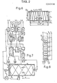
- An example of a possible, simplified electrical blocks diagram with all the modifications described is reported in fig. 7, which shows the container (W), the optical system of mirros (sp, sp1, sp2 and sp3), the laser z with the beam-dividing reflecting prism (g) and the crystal frequency transformer (f).
- Fig. 4 shows the crossed laser beams, one oriented toward the left and one towards the right, describing some close, segmented paths as a result of the reflections on the four flat mirrors.
- Am and Am1 At the ends of the photodetectors' light-sensitive areas, there are two amplifiers (Am and Am1) directed towards the t x and t y times meter for a comparison with the laser start impulses and the standard electronic clock in order to calculate the ⁇ time, determined by the presence of a possible ⁇ rotation.
- the value processed by EL is transferred to the D unit and to the D p indica tor with the numerical display. At the same time, it is also transferred to the CI control block where there is an input device (U), used for collecting compatible signals deriving from inertial auxiliary system to be added with the laser signals, and used, if necessary, for producing corrective signals, through which the position of the container (W) may be changed, by means of the m o and m o1 motors.
- U input device
- the M e stores containing the basic reference motion data, permitting the measurements to be carried out, and to be used in order to guide the programmed processing of ⁇ and V. They represent the basic setting of the meter at the starting point.
- connection taps which may be used for transmitting outside signals, to eventually operate possible direct control, on commands which can modify the relative trajectory (or V M speed) or the relative ⁇ rotation of the mobile.
- low measures may be taken within the K span, with K representing the span of velocity values which include the true value of the W velocity unkow V M , without V p , subtracted vectorially, becase it represents the constant share of motion acquired before the start of the mobile (or the share already considered during the setting operations).
- Fig. 9 shows two diagrams: "A” represents the light impulses released by the laser, and "B” represents the same impulses received by the photodetector.
- a codification based, for instance, on the introduction of a time interval ⁇ without signals followed by a first, stronger impulse ( ⁇ 1) divides a sequence of other normal impulses from the following sequence (A1) by t1.
- the incoming ⁇ signals may therefore be recognized and related to those released by the laster (z), thus determining the time interval to be measured between the release and the arrival of each of them.
- the time interval is rather long, let us say some dozen milliseconds, (which depends on the length of the mirrors and the distance between them, (namely l and L) it is not necessary to wait so long before emitting new light impulses. They may be emitted continuously, thereby obtaining new measures in an equally continuous fashion.
- the whole computer system will have to be enlarged to enable it to interpolate the data of the three indicators, thus obtaining the real movements of the mobile, projected onto the x, y and z planes, form another location taken as a reference point with a preliminary setting.
- the laser z, z1 and z2 In front of the faces a1, b1 and c1 are located the laser z, z1 and z2, with the crystals f, f1 and f2 for the change of wave length ( ⁇ ) and the reflecting prisms g, f1 and g2 for the division of the light beams which enter the cube through the treated surface points P, P1, P2, P3, P4 and P5 in order to prevent the beam dividing heads from covering the reflecting surface of the mirrors in the important sites defined as S, S1 and S2.
- the lasers' wavelength are differentiated.
- the ⁇ value is taken to 600 nm in z, 400 nm in z1 and 300 nm in z2 in order to avoid interference between the data obtained simultaneously with the three optical systems oriented along the three orthogonal planes.
- b2 and C2 are located the photosensors L, L1 and L2 which select the respective ⁇ coming from the opposite faces.
- Such photosensors are located slightly below the reflecting surface of the mirrors. These surfaces, however, only allow the passage of the wavelength of any single optical beam, because a ⁇ light selection system is adopted.
- photosensors are double, and may select the beams coming from two opposite directions (d and d1) as shown in fig. 8.
- the lasers' electrical supply system is synchronized in order to have the same short impulse for all the three lasers (see fig. 9).
- the coordination of the analysis, processing and calculation of the final data on the basis of a pre-fixed initial situation will have to be different from the one described above.
- two further computer complexes fig.
- the container (W) may be metallic and strong, and it may contain only limited reflection areas and the other thin sectors where photosensors and their ⁇ filters are installed.
- the semiconductor lasers, equipped with the optical device for the formation of a thin beam, and their ⁇ transformers and beam-dividing reflecting prisms or equivalent dichroic mirrors, are located outside the cubic container (W), and they may also be grouped in a single rigid mounting, fixed as indicated in fig.
- the vector (V) may be calculated in its projections on the x, y and z planes through the measurement of times in the three optical circuits of the respective orthogonal planes, and it may then be compared with any other x, y and z vector calculated as a primary reference at the beginning of a given motion or with a calibration calculated on the basis of the principle of the constant speed of light and of its unchanging direction of propagation, a principle which is valid in any portion of space. If there is only one optical system, as shown in fig.
- the wavelength of the r and r1 laser beams may be changed one from the other by means of two plate glasses (f), after reflection on the way out of the prisms (g).
- the distinction between them at the adjacent, electrically divided double photodetector may be carried out by two transparent filters for the two different transformed wavelenghts of r and r1.
Landscapes
- Physics & Mathematics (AREA)
- Engineering & Computer Science (AREA)
- General Physics & Mathematics (AREA)
- Optics & Photonics (AREA)
- Electromagnetism (AREA)
- Power Engineering (AREA)
- Radar, Positioning & Navigation (AREA)
- Remote Sensing (AREA)
- Gyroscopes (AREA)
- Length Measuring Devices By Optical Means (AREA)
Applications Claiming Priority (2)
| Application Number | Priority Date | Filing Date | Title |
|---|---|---|---|
| IT82802/87A IT1221708B (it) | 1987-01-14 | 1987-01-14 | Perfezionamenti del sistema ottico-elettronico di determinazione della direzione e della velocita' di un veicolo a mezzo laser interno,applicati anche per rilevare contemporaneamente rotazioni trasversali |
| IT8280287 | 1987-01-14 |
Publications (2)
| Publication Number | Publication Date |
|---|---|
| EP0286598A2 true EP0286598A2 (de) | 1988-10-12 |
| EP0286598A3 EP0286598A3 (de) | 1991-07-31 |
Family
ID=11319240
Family Applications (1)
| Application Number | Title | Priority Date | Filing Date |
|---|---|---|---|
| EP19880830010 Withdrawn EP0286598A3 (de) | 1987-01-14 | 1988-01-12 | Opto-elektronische Anordnung zur Bestimmung von Richtung und Geschwindigkeit eines Fahrzeuges mittels Laserstrahlung und gleichzeitige Messung der Rotation |
Country Status (2)
| Country | Link |
|---|---|
| EP (1) | EP0286598A3 (de) |
| IT (1) | IT1221708B (de) |
Cited By (3)
| Publication number | Priority date | Publication date | Assignee | Title |
|---|---|---|---|---|
| WO2003078922A1 (en) * | 2002-03-15 | 2003-09-25 | Adaptive Materials Technology-Adaptamat Oy | Method and apparatus for sensing |
| US9110088B1 (en) | 2014-02-10 | 2015-08-18 | Selwyn E. Wright | Propagation medium velocity measurement system |
| ES2849571A1 (es) * | 2020-02-18 | 2021-08-19 | Cuesta Sanchez Ramon Manuel | Dispositivo y equipo de medicion de velocidad e indicador de direccion sin puntos de referencia |
Families Citing this family (1)
| Publication number | Priority date | Publication date | Assignee | Title |
|---|---|---|---|---|
| CN112881997B (zh) * | 2020-12-29 | 2024-05-24 | 中国航空工业集团公司西安飞机设计研究所 | 一种基于雷达激光靶的高精度组合式调平方法 |
Family Cites Families (4)
| Publication number | Priority date | Publication date | Assignee | Title |
|---|---|---|---|---|
| US3102953A (en) * | 1958-07-09 | 1963-09-03 | Maxson Electronics Corp | Electromagnetic wave gyroscopes or angular velocity measuring systems |
| US4585346A (en) * | 1983-03-17 | 1986-04-29 | The Singer Company | Pathlength controller for three-axis ring laser gyroscope assembly |
| IT1199583B (it) * | 1984-09-19 | 1988-12-30 | Licinio Ugo | Sistema ottico-elettronico predisposto per la determinazione della velocita'di un veicolo in moto a mezzo raggio laser |
| IT1204231B (it) * | 1986-05-27 | 1989-03-01 | Ugo Licinio | Perfezionamenti relativi al sistema ottico elettronico,predisposto per la determinazione della direzione e della velocita' di un veicolo in moto a mezzo di emissione interna di raggi laser |
-
1987
- 1987-01-14 IT IT82802/87A patent/IT1221708B/it active
-
1988
- 1988-01-12 EP EP19880830010 patent/EP0286598A3/de not_active Withdrawn
Cited By (3)
| Publication number | Priority date | Publication date | Assignee | Title |
|---|---|---|---|---|
| WO2003078922A1 (en) * | 2002-03-15 | 2003-09-25 | Adaptive Materials Technology-Adaptamat Oy | Method and apparatus for sensing |
| US9110088B1 (en) | 2014-02-10 | 2015-08-18 | Selwyn E. Wright | Propagation medium velocity measurement system |
| ES2849571A1 (es) * | 2020-02-18 | 2021-08-19 | Cuesta Sanchez Ramon Manuel | Dispositivo y equipo de medicion de velocidad e indicador de direccion sin puntos de referencia |
Also Published As
| Publication number | Publication date |
|---|---|
| IT8782802A0 (it) | 1987-01-14 |
| IT1221708B (it) | 1990-07-12 |
| EP0286598A3 (de) | 1991-07-31 |
Similar Documents
| Publication | Publication Date | Title |
|---|---|---|
| US4939678A (en) | Method for calibration of coordinate measuring machine | |
| US4523846A (en) | Integrated optics in an electrically scanned imaging Fourier transform spectrometer | |
| US4884889A (en) | Calibration system for coordinate measuring machine | |
| US4697927A (en) | Method and apparatus for measuring a forming error of an object | |
| US5268739A (en) | Laser apparatus for measuring the velocity of a fluid | |
| US3597091A (en) | Interferometer | |
| AU2006201171A1 (en) | Optical accelerometer, optical inclinometer and seismic sensor system using such accelerometer and inclinometer | |
| WO1992004619A1 (en) | Reflective optical instrument | |
| RU2275652C2 (ru) | Способ локации источника излучения и устройство для его реализации | |
| US5239364A (en) | Light phase difference measuring method using an interferometer | |
| EP0286598A2 (de) | Opto-elektronische Anordnung zur Bestimmung von Richtung und Geschwindigkeit eines Fahrzeuges mittels Laserstrahlung und gleichzeitige Messung der Rotation | |
| US4666296A (en) | Velocity interferometer with continuously variable sensitivity | |
| RU2137097C1 (ru) | Оптическое трехкоординатное устройство контроля вибросмещений | |
| GB2280259A (en) | Detecting angular displacement. | |
| Williams et al. | Two wavelength angular refraction measurement | |
| SU1040444A1 (ru) | Деформограф | |
| SU953609A1 (ru) | Кварцевый гравиметр | |
| SU1043486A1 (ru) | Устройство дл измерени углового перемещени объекта | |
| SU1523907A1 (ru) | Сферометр | |
| RU2069308C1 (ru) | Датчик углового положения | |
| SU600499A1 (ru) | Теневое автоколлимационное устройство | |
| SU1714515A1 (ru) | Волоконно-оптический гироскоп | |
| RU1774233C (ru) | Способ определени линейных перемещений объектов с плоской зеркально-отражающей поверхностью | |
| SU1158860A1 (ru) | Интерферометр дл измерени углового положени объекта | |
| SU1397718A1 (ru) | Интерферометр дл измерени линейных величин и показател преломлени |
Legal Events
| Date | Code | Title | Description |
|---|---|---|---|
| PUAI | Public reference made under article 153(3) epc to a published international application that has entered the european phase |
Free format text: ORIGINAL CODE: 0009012 |
|
| AK | Designated contracting states |
Kind code of ref document: A2 Designated state(s): DE FR GB |
|
| 17P | Request for examination filed |
Effective date: 19890503 |
|
| PUAL | Search report despatched |
Free format text: ORIGINAL CODE: 0009013 |
|
| AK | Designated contracting states |
Kind code of ref document: A3 Designated state(s): DE FR GB |
|
| 17Q | First examination report despatched |
Effective date: 19921217 |
|
| STAA | Information on the status of an ep patent application or granted ep patent |
Free format text: STATUS: THE APPLICATION HAS BEEN WITHDRAWN |
|
| 18W | Application withdrawn |
Withdrawal date: 19930213 |