EP0286604B1 - System für das schnelle Aufspannen von Formen in einer horizontalen Presse zum Spritzgiessen von Kunststoff - Google Patents
System für das schnelle Aufspannen von Formen in einer horizontalen Presse zum Spritzgiessen von Kunststoff Download PDFInfo
- Publication number
- EP0286604B1 EP0286604B1 EP88830127A EP88830127A EP0286604B1 EP 0286604 B1 EP0286604 B1 EP 0286604B1 EP 88830127 A EP88830127 A EP 88830127A EP 88830127 A EP88830127 A EP 88830127A EP 0286604 B1 EP0286604 B1 EP 0286604B1
- Authority
- EP
- European Patent Office
- Prior art keywords
- attachment structures
- clamping
- die
- dies
- plate
- Prior art date
- Legal status (The legal status is an assumption and is not a legal conclusion. Google has not performed a legal analysis and makes no representation as to the accuracy of the status listed.)
- Expired
Links
- 238000001746 injection moulding Methods 0.000 title claims abstract description 6
- 239000000463 material Substances 0.000 title claims abstract description 6
- 229920003023 plastic Polymers 0.000 title claims abstract description 6
- 239000004033 plastic Substances 0.000 title claims abstract description 6
- 239000012530 fluid Substances 0.000 claims description 3
- 238000003780 insertion Methods 0.000 description 2
- 230000037431 insertion Effects 0.000 description 2
- 230000000295 complement effect Effects 0.000 description 1
- 230000000694 effects Effects 0.000 description 1
- 230000008030 elimination Effects 0.000 description 1
- 238000003379 elimination reaction Methods 0.000 description 1
- 238000004519 manufacturing process Methods 0.000 description 1
- 238000000034 method Methods 0.000 description 1
- 230000000284 resting effect Effects 0.000 description 1
- 238000005096 rolling process Methods 0.000 description 1
Images


Classifications
-
- B—PERFORMING OPERATIONS; TRANSPORTING
- B29—WORKING OF PLASTICS; WORKING OF SUBSTANCES IN A PLASTIC STATE IN GENERAL
- B29C—SHAPING OR JOINING OF PLASTICS; SHAPING OF MATERIAL IN A PLASTIC STATE, NOT OTHERWISE PROVIDED FOR; AFTER-TREATMENT OF THE SHAPED PRODUCTS, e.g. REPAIRING
- B29C45/00—Injection moulding, i.e. forcing the required volume of moulding material through a nozzle into a closed mould; Apparatus therefor
- B29C45/17—Component parts, details or accessories; Auxiliary operations
- B29C45/1742—Mounting of moulds; Mould supports
Definitions
- the present invention is applicable to horizontal presses for the injection moulding of plastics materials, of the type comprising a pair of facing vertical support plates which are displaceable horizontally relative to each other and are arranged for the removable fixing of respective dies provided with fixing flanges.
- the fixed and movable plates have a plurality of grooves intended to enable connection of the fixing flanges of the dies.
- This connection is effected directly and manually by means of clamps and bolts, and involves complicated and difficult operations and long periods during which the press is inoperative.
- the object of the present invention is to avoid these disadvantages by making the operations of fitting and removal of the dies quick and easy to carry out so as to reduce to a minimum the time for which the press is stopped when it is necessary to replace the dies.
- each of the plates of the press is provided with a pair of attachment structures fixed permanently along two opposite sides of the plate and define therewith two guides which are adapted slidably to receive the fixing flanges of the die, and with which are associated motor-driven clamping means which can be operated simultaneously to clamp the fixing flanges to the attachment structures.
- the motor-driven clamping means preferably include a series of horizontal rods perpendicular to the plates of the press and movable axially relative to the attachment structures between a retracted rest position and an extended clamping position, the rods carrying respective sprocket wheels meshing with rack sections which are interconnected and movable jointly along the two attachment structures by means of respective linear pressurised-fluid actuators.
- Each rack section is conveniently carried by a respective sliding runner which is slidable along a longitudinal guide of the corresponding attachment structure and rigidly connected to the sliding runner of the adjacent rack sector.
- the two attachment structures may be fitted along the upper and lower horizontal edges of the respective plate of the press, or along the lateral edges thereof.
- insertion of the die into the guides of the attachment structure is effected from the side, whilst in the second case it is carried out from above.
- a vertical support or movable plate of a horizontal press for the injection moulding of plastics materials is indicated 1.
- This press is of generally known type and, for brevity, will not therefore be described in detail.
- the press includes four cylindrical horizontal guide bars 2 arranged as the vertices of a quadrilateral and on which the support plate 1 (movable plate) is slidably mounted so as to be movable towards and away from a fixed counterplate (fixed plate), not illustrated, which is exactly the same as the plate 1.
- the movable plate 1 is arranged, in the manner made clear below, to support a die S provided with fixing flanges F.
- the conformation of the movable plate 1 and its system for retaining the die S are exactly the same as those of the fixed plate, so the following description relating to the plate 1 also applies identically to the counterplate.
- the working face of the movable plate 1 that is, the face intended to receive the die S, has a plurality of grooves 3 perpendicular to its edges and used, according to known techniques, for the direct fixing of the flanges F of the die S by means of brackets and bolts.
- the grooves 3 are used for the permanent fixing of a pair of attachment structures, generally indicated 4, which serve, in the manner explained below, for the mechanised clamping of the die S.
- the two attachment structures 4 are arranged vertically along the side edges of the plate 1 and are fixed by means of respective bolts 5 to the horizontal grooves 3. It should be noted, however, that the two attachment structures 4 could be arranged horizontally along the upper side and the lower side of the plate 1, the bolts 5 being engaged in the vertical grooves 3.
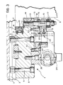
- the two attachment structures 4 have an identical conformation, illustrated in greater detail in Figure 3.
- Each of these structures 4 comprises a base 6 carrying the bolts 5 for attachment to the plate 1 of the press and having, in correspondence with its inner side, that is, the side facing the other attachment structure 4, an L-shaped recess, indicated 7, which defines with the working face of the plate 1 a sliding guide 8 having a shape complementary to that of the flanges F of the die S.
- the guide 8 has a width which is slightly greater than the thickness of the flanges F.
- a sprocket wheel 16 which is urged axially by the action of a spring assembly 17 against a thrust bearing 18 mounted in the female thread 13.
- the sprocket wheel 16 and the shaft 15 are fast for rotation with each other, whilst the shaft 15 is axially slidable relative to the sprocket 16.
- the sprocket wheel 16 meshes with a rack section 19 carried by a sliding runner 20 which is slidable vertically within a prismatic guide 21 defined by two L-shaped profiles 22 fixed by means of screws 23 to the face of the base 6 opposite to the plate 1.
- the sliding runners 20 carrying the rack sections 19 associated with the sprocket wheels 16 of the various rods 15 are interconnected by means of vertical interconnecting elements 23 for simultaneous vertical movement along the sliding guide 21.
- a pressurised-fluid jack 24 is provided to effect this vertical movement, and its cylinder 25 is carried by an attachment 26 fixed to the base 6 while its piston 27 is fixed to a side arm 28 fixed to one of the sliding runners 20.
- operation of the jack 24 causes the vertical translation in one direction or in the opposite direction of the sliding runners 20 interconnected by the connecting members 23, by means of the piston 27 and the arm 28, and hence the screwing and unscrewing of the rods 15 relative to the female threads 13, by means of the meshing between the rack sections 19 and the sprocket wheels 16.
- the operation of the jack 24 causes the simultaneous retraction or extension of the rods 15 relative to the sliding guide 8, in order to enable easy and rapid replacement of the die S in the manner explained below.
- the rods 15 are disposed in the retracted position and the die S is lowered from above (normally by means of an overhead crane) so that its flanges F are introduced into the sliding guides 8 of the attachment structures 4.
- the die S is then lowered and positioned vertically along the guides 8 with the help of the roller units 9 which facilitate the sliding of the flanges F.
- the two jacks 24 associated with the two attachment structures 4 are activated so as to cause the simultaneous advance of the rods 15 and the clamping of the flanges F of the die S against the working face of the plate 1.
- the above-described operations are carried out in reverse, that is, the rods 15 are simutaneously retracted so as to release the flanges F and enable them to slide upwards along the guides 8 until the die S is completely raised.
- attachment structures 4 enables the operations of replacement of the dies to be made considerably easier and quicker with a drastic reduction in the period for which the press is inoperative and thus, in point of fact, with a considerable increase in its productivity.
Landscapes
- Engineering & Computer Science (AREA)
- Manufacturing & Machinery (AREA)
- Mechanical Engineering (AREA)
- Moulds For Moulding Plastics Or The Like (AREA)
- Injection Moulding Of Plastics Or The Like (AREA)
- Mounting, Exchange, And Manufacturing Of Dies (AREA)
- Casting Or Compression Moulding Of Plastics Or The Like (AREA)
Claims (5)
Priority Applications (1)
| Application Number | Priority Date | Filing Date | Title |
|---|---|---|---|
| AT88830127T ATE76801T1 (de) | 1987-04-07 | 1988-03-29 | System fuer das schnelle aufspannen von formen in einer horizontalen presse zum spritzgiessen von kunststoff. |
Applications Claiming Priority (2)
| Application Number | Priority Date | Filing Date | Title |
|---|---|---|---|
| IT8767287A IT1207549B (it) | 1987-04-07 | 1987-04-07 | Sistema di staffaggio rapido degli stampi su una pressa orizzontale per lo stampaggio ad iniezione di materie plastiche |
| IT6728787 | 1987-04-07 |
Publications (3)
| Publication Number | Publication Date |
|---|---|
| EP0286604A2 EP0286604A2 (de) | 1988-10-12 |
| EP0286604A3 EP0286604A3 (en) | 1990-01-31 |
| EP0286604B1 true EP0286604B1 (de) | 1992-06-03 |
Family
ID=11301165
Family Applications (1)
| Application Number | Title | Priority Date | Filing Date |
|---|---|---|---|
| EP88830127A Expired EP0286604B1 (de) | 1987-04-07 | 1988-03-29 | System für das schnelle Aufspannen von Formen in einer horizontalen Presse zum Spritzgiessen von Kunststoff |
Country Status (7)
| Country | Link |
|---|---|
| US (1) | US4867666A (de) |
| EP (1) | EP0286604B1 (de) |
| JP (1) | JPS63272517A (de) |
| AT (1) | ATE76801T1 (de) |
| DE (1) | DE3871595T2 (de) |
| ES (1) | ES2032053T3 (de) |
| IT (1) | IT1207549B (de) |
Families Citing this family (10)
| Publication number | Priority date | Publication date | Assignee | Title |
|---|---|---|---|---|
| US5096404A (en) * | 1990-10-31 | 1992-03-17 | At&T Bell Laboratories | Quick mold change arrangement for injection molding machines |
| US5302103A (en) * | 1991-10-10 | 1994-04-12 | Gencorp Inc. | Injection molding machine including quick-change mold assembly |
| US6010324A (en) * | 1996-01-30 | 2000-01-04 | Toshiba Kikai Kabushiki Kaisha | Mold clamping unit and method of positioning mold in mold clamping unit |
| DE102007051521A1 (de) * | 2007-10-19 | 2009-04-23 | Seereal Technologies S.A. | Dynamische Wellenformereinheit |
| CN101774259B (zh) * | 2009-01-12 | 2013-10-09 | 鸿富锦精密工业(深圳)有限公司 | 成型模具 |
| DE102011055961A1 (de) | 2011-12-02 | 2013-06-06 | B & R GmbH | Spritzgussvorrichtung zum Spritzgießen von Kunststoffmaterialien |
| JP5342668B2 (ja) * | 2012-04-02 | 2013-11-13 | ファナック株式会社 | 射出成形機の型締機構 |
| DE102012103241A1 (de) | 2012-04-13 | 2013-10-17 | B & R GmbH | Spritzgussvorrichtung zum Spritzgießen von Kunststoffmaterialien |
| DE102014107762B4 (de) | 2014-06-03 | 2021-09-16 | Hasco Hasenclever Gmbh + Co Kg | Spritzgussvorrichtung zum Spritzgießen von Kunststoffmaterialien |
| CN106426760A (zh) * | 2016-11-24 | 2017-02-22 | 无锡海天机械有限公司 | 一种适用于圆形模具安装的注塑机模板 |
Family Cites Families (3)
| Publication number | Priority date | Publication date | Assignee | Title |
|---|---|---|---|---|
| DE3127797A1 (de) * | 1981-07-14 | 1983-02-03 | Mannesmann Demag Kunstofftechnik Zweigniederlassung der Mannesmann Demag AG, 8500 Nürnberg | Aufspann- und anschlussvorrichtung fuer werkzeuge von spritzgiessmaschinen und damit zu verwendendes werkzeug |
| EP0092685B2 (de) * | 1982-04-26 | 1995-08-02 | Battenfeld GmbH | Schnellwechsel- und/oder Spannvorrichtung für die Formwerkzeuge von Spritzgiessmaschinen |
| US4500275A (en) * | 1983-12-23 | 1985-02-19 | Sharp Die & Mold Company, Inc., A Subsidiary Of R & R Plastic Material, Inc. | Quick change locator clamp assembly for plastic molding machine |
-
1987
- 1987-04-07 IT IT8767287A patent/IT1207549B/it active
-
1988
- 1988-03-29 DE DE8888830127T patent/DE3871595T2/de not_active Expired - Lifetime
- 1988-03-29 ES ES198888830127T patent/ES2032053T3/es not_active Expired - Lifetime
- 1988-03-29 EP EP88830127A patent/EP0286604B1/de not_active Expired
- 1988-03-29 AT AT88830127T patent/ATE76801T1/de not_active IP Right Cessation
- 1988-04-06 US US07/178,095 patent/US4867666A/en not_active Expired - Fee Related
- 1988-04-06 JP JP63086255A patent/JPS63272517A/ja active Pending
Also Published As
| Publication number | Publication date |
|---|---|
| JPS63272517A (ja) | 1988-11-10 |
| IT1207549B (it) | 1989-05-25 |
| ES2032053T3 (es) | 1993-01-01 |
| DE3871595D1 (de) | 1992-07-09 |
| IT8767287A0 (it) | 1987-04-07 |
| EP0286604A3 (en) | 1990-01-31 |
| DE3871595T2 (de) | 1992-12-03 |
| EP0286604A2 (de) | 1988-10-12 |
| ATE76801T1 (de) | 1992-06-15 |
| US4867666A (en) | 1989-09-19 |
Similar Documents
| Publication | Publication Date | Title |
|---|---|---|
| DE2421811C2 (de) | Formschließeinheit für eine Kunststoff-Spritzgießmaschine mit einem Schiebetisch | |
| US4258620A (en) | Tool fastening means for a press | |
| US4867666A (en) | System for the rapid clamping of dies on a horizontal press for the injection moulding of plastics materials | |
| DE2607371B2 (de) | Vorrichtung zur Herstellung von Hohlkörpern aus Bandmaterial | |
| CN210189185U (zh) | 一种铝合金型材切割设备用出料装置 | |
| DE69823475T2 (de) | Transfereinrichtung für eine Schmiedepresse | |
| CN212857342U (zh) | 一种适用于风电塔筒爬梯边框的冲孔设备 | |
| US3427855A (en) | Movable bolster for presses | |
| DE3620954C2 (de) | ||
| DE3103038C2 (de) | Vorrichtung zum Herstellen eines im wesentlichen aus zwei Halbschalen gebildeten Hohlkörpers | |
| CN212425338U (zh) | 一种机械加工车间物料搬运叉车用的铲料组件 | |
| CN214489793U (zh) | 一种刮刀切割用定位装置 | |
| CN105081123A (zh) | 汽车手工线上下料辅助机构 | |
| CN115365347B (zh) | 一种型钢煨弯机 | |
| US2878559A (en) | Mounting and demounting press | |
| DE69125720T2 (de) | Vorrichtung zum Wechseln von Werkzeugen bei Blasformmaschinen | |
| CN211765678U (zh) | 一种快速换模小车 | |
| US3844151A (en) | Extrusion press with die changer | |
| DE2544711B2 (de) | Schnellspannwerkzeug für Schmiedepressen | |
| CN223043340U (zh) | 一种卧式冷拔机 | |
| EP0884151A1 (de) | Anlage zum Druckgiessen keramischer Artikel | |
| CN210450811U (zh) | 圆环链链环挤环机 | |
| CN217752673U (zh) | 一种挤出机的模头更换辅助架 | |
| CN218286863U (zh) | 一种用于零部件装配的简易压力机 | |
| US3273369A (en) | Straightening machine |
Legal Events
| Date | Code | Title | Description |
|---|---|---|---|
| PUAI | Public reference made under article 153(3) epc to a published international application that has entered the european phase |
Free format text: ORIGINAL CODE: 0009012 |
|
| AK | Designated contracting states |
Kind code of ref document: A2 Designated state(s): AT BE CH DE ES FR GB GR IT LI LU NL SE |
|
| RAP1 | Party data changed (applicant data changed or rights of an application transferred) |
Owner name: FIAT AUTO S.P.A. |
|
| PUAL | Search report despatched |
Free format text: ORIGINAL CODE: 0009013 |
|
| AK | Designated contracting states |
Kind code of ref document: A3 Designated state(s): AT BE CH DE ES FR GB GR IT LI LU NL SE |
|
| 17P | Request for examination filed |
Effective date: 19900511 |
|
| 17Q | First examination report despatched |
Effective date: 19910814 |
|
| GRAA | (expected) grant |
Free format text: ORIGINAL CODE: 0009210 |
|
| AK | Designated contracting states |
Kind code of ref document: B1 Designated state(s): AT BE CH DE ES FR GB GR IT LI LU NL SE |
|
| PG25 | Lapsed in a contracting state [announced via postgrant information from national office to epo] |
Ref country code: IT Free format text: LAPSE BECAUSE OF FAILURE TO SUBMIT A TRANSLATION OF THE DESCRIPTION OR TO PAY THE FEE WITHIN THE PRE;WARNING: LAPSES OF ITALIAN PATENTS WITH EFFECTIVE DATE BEFORE 2007 MAY HAVE OCCURRED AT ANY TIME BEFORE 2007. THE CORRECT EFFECTIVE DATE MAY BE DIFFERENT FROM THE ONE RECORDED.SCRIBED TIME-LIMIT Effective date: 19920603 Ref country code: GR Free format text: LAPSE BECAUSE OF FAILURE TO SUBMIT A TRANSLATION OF THE DESCRIPTION OR TO PAY THE FEE WITHIN THE PRESCRIBED TIME-LIMIT Effective date: 19920603 Ref country code: AT Effective date: 19920603 Ref country code: NL Effective date: 19920603 Ref country code: CH Effective date: 19920603 Ref country code: BE Effective date: 19920603 Ref country code: LI Effective date: 19920603 |
|
| REF | Corresponds to: |
Ref document number: 76801 Country of ref document: AT Date of ref document: 19920615 Kind code of ref document: T |
|
| REF | Corresponds to: |
Ref document number: 3871595 Country of ref document: DE Date of ref document: 19920709 |
|
| ET | Fr: translation filed | ||
| REG | Reference to a national code |
Ref country code: CH Ref legal event code: PL |
|
| NLV1 | Nl: lapsed or annulled due to failure to fulfill the requirements of art. 29p and 29m of the patents act | ||
| REG | Reference to a national code |
Ref country code: ES Ref legal event code: FG2A Ref document number: 2032053 Country of ref document: ES Kind code of ref document: T3 |
|
| PG25 | Lapsed in a contracting state [announced via postgrant information from national office to epo] |
Ref country code: LU Free format text: LAPSE BECAUSE OF NON-PAYMENT OF DUE FEES Effective date: 19930331 |
|
| PLBE | No opposition filed within time limit |
Free format text: ORIGINAL CODE: 0009261 |
|
| STAA | Information on the status of an ep patent application or granted ep patent |
Free format text: STATUS: NO OPPOSITION FILED WITHIN TIME LIMIT |
|
| 26N | No opposition filed | ||
| PGFP | Annual fee paid to national office [announced via postgrant information from national office to epo] |
Ref country code: GB Payment date: 19940216 Year of fee payment: 7 |
|
| PGFP | Annual fee paid to national office [announced via postgrant information from national office to epo] |
Ref country code: SE Payment date: 19940223 Year of fee payment: 7 |
|
| PGFP | Annual fee paid to national office [announced via postgrant information from national office to epo] |
Ref country code: ES Payment date: 19940310 Year of fee payment: 7 |
|
| EAL | Se: european patent in force in sweden |
Ref document number: 88830127.2 |
|
| PG25 | Lapsed in a contracting state [announced via postgrant information from national office to epo] |
Ref country code: GB Effective date: 19950329 |
|
| PG25 | Lapsed in a contracting state [announced via postgrant information from national office to epo] |
Ref country code: SE Effective date: 19950330 Ref country code: ES Free format text: LAPSE BECAUSE OF NON-PAYMENT OF DUE FEES Effective date: 19950330 |
|
| GBPC | Gb: european patent ceased through non-payment of renewal fee |
Effective date: 19950329 |
|
| EUG | Se: european patent has lapsed |
Ref document number: 88830127.2 |
|
| PGFP | Annual fee paid to national office [announced via postgrant information from national office to epo] |
Ref country code: DE Payment date: 19970224 Year of fee payment: 10 |
|
| PGFP | Annual fee paid to national office [announced via postgrant information from national office to epo] |
Ref country code: FR Payment date: 19970327 Year of fee payment: 10 |
|
| PG25 | Lapsed in a contracting state [announced via postgrant information from national office to epo] |
Ref country code: FR Free format text: THE PATENT HAS BEEN ANNULLED BY A DECISION OF A NATIONAL AUTHORITY Effective date: 19980331 |
|
| PG25 | Lapsed in a contracting state [announced via postgrant information from national office to epo] |
Ref country code: DE Free format text: LAPSE BECAUSE OF NON-PAYMENT OF DUE FEES Effective date: 19981201 |
|
| REG | Reference to a national code |
Ref country code: FR Ref legal event code: ST |
|
| REG | Reference to a national code |
Ref country code: ES Ref legal event code: FD2A Effective date: 19990503 |