EP0286621A1 - Baukastenelement zur Herstellung von Schubladen und ihre Anordnung in einem Möbelregal - Google Patents
Baukastenelement zur Herstellung von Schubladen und ihre Anordnung in einem Möbelregal Download PDFInfo
- Publication number
- EP0286621A1 EP0286621A1 EP88870056A EP88870056A EP0286621A1 EP 0286621 A1 EP0286621 A1 EP 0286621A1 EP 88870056 A EP88870056 A EP 88870056A EP 88870056 A EP88870056 A EP 88870056A EP 0286621 A1 EP0286621 A1 EP 0286621A1
- Authority
- EP
- European Patent Office
- Prior art keywords
- panel
- panels
- rack
- drawers
- parts
- Prior art date
- Legal status (The legal status is an assumption and is not a legal conclusion. Google has not performed a legal analysis and makes no representation as to the accuracy of the status listed.)
- Granted
Links
- 238000010276 construction Methods 0.000 title claims description 15
- 239000002184 metal Substances 0.000 claims abstract description 6
- 229910052751 metal Inorganic materials 0.000 claims abstract description 6
- 230000000284 resting effect Effects 0.000 claims 1
- 210000002105 tongue Anatomy 0.000 description 6
- 241000120551 Heliconiinae Species 0.000 description 2
- 229910000746 Structural steel Inorganic materials 0.000 description 2
- 238000000034 method Methods 0.000 description 2
- 239000000853 adhesive Substances 0.000 description 1
- 230000001070 adhesive effect Effects 0.000 description 1
- 239000002390 adhesive tape Substances 0.000 description 1
- 230000006355 external stress Effects 0.000 description 1
- 239000003292 glue Substances 0.000 description 1
- 230000035882 stress Effects 0.000 description 1
Images


Classifications
-
- A—HUMAN NECESSITIES
- A47—FURNITURE; DOMESTIC ARTICLES OR APPLIANCES; COFFEE MILLS; SPICE MILLS; SUCTION CLEANERS IN GENERAL
- A47B—TABLES; DESKS; OFFICE FURNITURE; CABINETS; DRAWERS; GENERAL DETAILS OF FURNITURE
- A47B67/00—Chests; Dressing-tables; Medicine cabinets or the like; Cabinets characterised by the arrangement of drawers
- A47B67/04—Chests of drawers; Cabinets characterised by the arrangement of drawers
-
- A—HUMAN NECESSITIES
- A47—FURNITURE; DOMESTIC ARTICLES OR APPLIANCES; COFFEE MILLS; SPICE MILLS; SUCTION CLEANERS IN GENERAL
- A47B—TABLES; DESKS; OFFICE FURNITURE; CABINETS; DRAWERS; GENERAL DETAILS OF FURNITURE
- A47B88/00—Drawers for tables, cabinets or like furniture; Guides for drawers
- A47B88/90—Constructional details of drawers
- A47B2088/902—Corner connectors for drawers
Definitions
- the present invention relates to sets of parts which allow the easy and rapid construction of one or more drawers and their mounting in furniture, in particular in pieces of furniture to be assembled yourself.
- each of the outer sides of the sides is provided with one or more grooves intended to receive one or more ribs fixed on the inner faces of the sides of the rack.
- the object of the present invention is to remedy these problems by providing sets of parts. spare parts that can be assembled by simple fitting, allowing the construction of drawers and their mounting in furniture. The drawers obtained can be easily disassembled from the said furniture and disassembled.
- Another object of the invention is to provide sets of parts sold separately, the assembly, assembly, disassembly and disassembly of which can be carried out without tools.
- Another object of the invention is to provide sets of parts making it possible to construct drawers for furniture to be assembled yourself, held by uprights which project towards the interior of the lockers, that is to say that these uprights are arranged in such a way that the distance between the internal faces of the sides of a rack is greater than the distance between the internal edges of the uprights arranged in front of the rack.
- an object of the invention is to provide removable drawers for furniture such as those whose construction system is described in French patent n ° 1 245 776 by Henry George KEWLEY, using for the construction of these drawers a system analogous to the construction system of this type of furniture.
- Said invention relates to a set of parts for the construction of one or more drawers and for their mounting in a cabinet locker maintained by anterior and posterior uprights, the distance between the internal faces of the sides of said rack being greater than the free space between the anterior uprights.
- the set of parts has two identical support panels between them and carrying as many horizontal grooves as there are drawers to be mounted and, for each drawer, a front panel and a rear panel identical to each other, a left panel and a straight panel identical to each other, a bottom panel and four metal angles, each wing of which is provided with a re-entrant flange which is perpendicular thereto.
- the front and rear panels are provided, in the lower part of their internal face, with a horizontal groove.
- the left and right panels have a height equal to that between the upper edge of one of the front or rear panels and the upper edge of the horizontal groove of said panel.
- the front, rear, left and right panels are provided with a 45 ° tab at each of their lateral edges on the side of their internal face and are provided, on their external face, with two vertical grooves near these lateral edges.
- the rectangular bottom panel has dimensions such that it engages on two of its sides in the horizontal grooves of the front and rear panels and that a tongue projects beyond either side of the external faces of the left panels and law. Each of these tabs can slide in one of the horizontal grooves provided on the internal face of each support panel.
- Each of the support panels has a length such that it can be accommodated between an anterior upright and a posterior upright along the internal face of one side of the rack and a thickness such that the distance between the internal faces of the support panels put in place is less than l space between the front uprights.
- the simple interlocking of the parts of the set of parts allows the assembly of one or more drawers and their mounting in a cabinet locker.
- the reverse operation allows disassembly of the drawer (s) outside the locker and disassembly of these drawers.
- each of the wings of each metal angle has a height equal to that of the panel in the vertical groove from which the edge of said wing engages.
- one of the identical front and rear panels is pierced with holes allowing the fixing of a handle, the other panel being pierced with a single hole allowing the fixing of a button.
- each support panel has a height equal to the internal height of a rack, and the internal space of said rack is entirely occupied by drawers.
- the set of parts further comprises a panel forming a shelf, which rests on the upper edge of each of the support panels, the said support panels having a height less than the internal height of the locker.
- At least one of the two support panels is provided, for each drawer to be mounted in the rack, with a flexible strip.
- Each flexible strip is screwed at one end under a horizontal groove, on the side of the support panel intended to be disposed towards the front of the rack. Its other end is intended to serve as a stop for the drawer. This end is free and spaced from the support panel, so as to be directed towards the bottom of the rack after the mounting of the support panel in the rack.
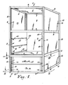
- Fig. 1 shows a piece of furniture 1 composed of three compartments 2, 3, 4 separated from each other by plates 5 constituting the bottom of each of the compartments 2, 3, 4. Each of these plates 5 is supported by a front cross member 6, a rear cross member 7 and two lateral crosspieces 8. Each rear crosspiece 7 carries a rear plate 9 constituting the back of the rack. Each of the lateral crosspieces 8 carries a side 10 of the rack 2, 3, 4.
- Furniture 1 is held by two front uprights 11 and two rear uprights 12, the front uprights 11 and rear 12 being identical in shape and made up of profiles each having two wings 13 perpendicular to each other (shown in Fig. 2) .
- Each wing 13 has a re-entrant flange 14 which is perpendicular thereto.
- the uprights 11 and 12 will be shown in more detail in FIG. 2.
- the rack 2 is provided with drawers 15 which will be shown in detail in FIGS. 3 to 6.
- the drawer 15 below is provided with a button 16, while the drawer 15 above is provided with a handle 17.
- the rack 3 In the rack 3, two support panels 18 are fitted, carrying as many horizontal grooves 19 as there are drawers 15 in the rack 3. In the embodiment illustrated in FIG. 1, the rack 3 is intended to receive three drawers 15.
- Each support panel 18 rests on the plate 5 constituting the bottom of the rack 3. It is placed between an anterior upright 11 and a posterior upright 12. The support panels 18 are not fixed in the cabinet but will be held in place by the drawers 15 when these are fitted in rack 3.
- FIG. 1 The structure of the cabinet 1 shown in FIG. 1 and the manner of mounting drawers 15 will be better understood by referring to Figs. 2 to 6.
- Fig. 2 shows the anterior uprights 11 and the posterior uprights 12 and the way in which they allow the assembly of the crosspieces 6, 7 and 8.
- Each of the crosspieces 6, 7 and 8 is miter cut at 45 ° at its lateral edges, on the side of its internal face, and carries, on its external face, two vertical grooves 20 each located near one of the two ends of said sleepers 6, 7 and 8.
- the uprights 11 and 12 thus make it possible to assemble the crosspieces 6, 7 and 8 two by two at a right angle, the re-entrant flanges 14 of the wings 13 each engaging in a vertical groove 20 of a crosspiece 6, 7 or 8.
- Each of the lateral crosspieces 8 is provided, along the entire length of its upper face, with a groove 21 in which, during the construction of the cabinet 1, the side 10 of the rack 2 will be housed.
- the crosspiece 7 is likewise provided with a groove 22 in which the rear plate 9 of the rack 2 will be housed.
- This rebate 23 is shown in FIGS. . 5 and 6.
- the front crossmember 6 does not have a groove intended to receive a plate. There remains at the front of the rack a free space between the front uprights 11. This free space is smaller than the distance between the internal faces of the sides 10 of the rack 2.
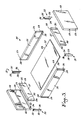
- Fig. 3 shows a set of parts 24 allowing the construction of a drawer 15 and its mounting in a cabinet 1.
- the assembly 24 has front and rear panels 25 identical to each other. Each of these front and rear panels 25 is provided, in the lower part of its internal face, with a horizontal groove 26.
- Each of these panels 27 has a height, measured from its upper edge to its lower edge, which is equal to the height between the upper edge of a front or rear panel 25 and the upper edge of the horizontal groove 26 of said panel 25.
- Each of the panels 25 and 27 is provided with a 45 ° tab, 28, formed on the internal face of each of its lateral edges.
- Each panel 25 is provided on its outer face with vertical grooves 29 and each panel 27 is provided on its outer face with vertical grooves 30.
- Each of the grooves 29 is close to one end of a panel 25 and each of the grooves 30 is close to one end of a panel 27.
- the panels 25 and 27 are assembled together, two by two, by means of angles 31 and 32 so as to form a frame, the upper edges of the panels 25 and 27 being located in the same horizontal plane.
- Each of the angles 31 is symmetrical of an angle 32.
- Each of these angles 31, 32 has a short wing 33 provided with a re-entrant edge 34 which is perpendicular thereto, and a long wing 35 provided with a re-entrant edge 36 which is perpendicular.
- each short wing 33 and its inside edge 34 is equal to the height of the panels 27, while the height of each long wing 35 and its inside edge 36 is equal to the height of the panels 25.
- each edge re-entering 34 of an angle iron 31 or 32 is engaged in a vertical groove 30 of the panel 27, while the re-entrant flange 35 of the same angle iron is engaged in a vertical groove 29 of the panel 25.
- the panels 25 and 27 are thus assembled at a right angle.
- the angles 31, 32 have a section identical to that of the uprights 11 and 12 and the assembly system of the panels 25, 27 of the drawer 15 is analogous to the assembly system of the crosspieces 6, 7, 8.
- the bottom panel 37 is introduced by its two sides 38 into the horizontal grooves 26 of the panels 25.
- the length of the sides 38 of the bottom panel 37 is greater than the length of the horizontal grooves 26 of the panels 25, which means that the bottom panel 37 protrudes at each end from the horizontal grooves 26 of the panels 25.
- each of the tongues 39 engages in one of the horizontal grooves 19 of a support panel 18.
- the tongues 39 play the role of slide and allow the drawer 15 to slide in the rack 2, by sliding each tab 39 in a horizontal groove 19 of a support panel 18.
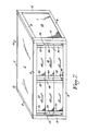
- Figs. 4, 5 and 6 show drawers 15 mounted in a rack 2 of a piece of furniture 1.
- Fig. 4 makes it possible to see cleats 40 placed inside the anterior 11 and posterior uprights 12. These cleats 40 are blocked inside the uprights 11 and 12 by the re-entrant flanges 14 of these uprights.
- the height of the support panels 13 is equal to the height of the cleats 40, which determines the height of the rack 2.
- Each of the sides 10 of the rack 2 is housed at each of its vertical ends in a groove 41 of a cleat 40, one of the cleats 40 being housed in an anterior upright 11 and the other of these cleats 40 being housed in a posterior upright 12.
- the rear plate 9 of the rack 2 is housed in the grooves 41 of the cleats 40 housed in the rear uprights 12.
- Figs. 4 and 5 there are the tongues 39 mentioned in the description of FIG. 3. Fig. 5 also makes it possible to see how these tongues 39 engage in the horizontal grooves 19 of the support panels 18.
- Figs. 1, 3, 4 and 6 we note the presence of flexible strips 42 which serve as stops for the drawers 15. These flexible strips 42 are screwed, by one of their ends, against the support panels 18, under the horizontal grooves 19 Each flexible strip 42 is fixed approximately three centimeters from the side of the support panel 18 intended to be disposed towards the front of the rack 2, 3 or 4. Its end free is directed towards the bottom of the locker 2, 3 or 4, in which it is placed. In the absence of external stresses, this free end is moved away from the support panel 18 by a distance of approximately one centimeter.
- This arrangement prevents the drawer 15 from falling out of the locker 2, 3 or 4.
- the flexible strips 42 are arranged on only one of the two support panels 18 present in a rack 2, 3 or 4.
- the support panels 18 may have a height less than the height of the sides 10 of a rack 2, 3 or 4.
- the internal space of the rack 2, 3 or 4 is not entirely filled with drawers 15, but a panel 43 forming a shelf (not shown in the figures) is placed on the upper edges of the support panels 18.
- Fig. 7 shows a rack 44 completely filled with drawers 15. These drawers 15 are divided into two juxtaposed series each comprising three superimposed drawers 15. The two series of drawers 15 are separated by a central support panel 45. On each face of this central support panel 45 are formed three horizontal grooves 46.
- Two support panels 18 are placed in the rack 44, in a manner identical to that illustrated in FIGS. 1 and 4 to 6.
- Each drawer 15 engages, by its tongues 39 (not shown), on the one hand in a horizontal groove 19 of one of the lateral support panels 18 and on the other hand in a horizontal groove 46 of the central support panel 45 .
- a small stop (not shown) can be fixed on the lower cross member 6, in front of said central support panel 45.
- the central support panel 45 can be replaced by two support panels 18 placed back to back and made integral with an adhesive (for example, double-sided adhesive tape). This procedure makes it possible to reduce the number of different parts to be manufactured.
- an adhesive for example, double-sided adhesive tape
Landscapes
- Assembled Shelves (AREA)
- Drawers Of Furniture (AREA)
- Container, Conveyance, Adherence, Positioning, Of Wafer (AREA)
- Compositions Of Macromolecular Compounds (AREA)
Priority Applications (1)
| Application Number | Priority Date | Filing Date | Title |
|---|---|---|---|
| AT88870056T ATE64836T1 (de) | 1987-04-09 | 1988-04-08 | Baukastenelement zur herstellung von schubladen und ihre anordnung in einem moebelregal. |
Applications Claiming Priority (2)
| Application Number | Priority Date | Filing Date | Title |
|---|---|---|---|
| FR8705035 | 1987-04-09 | ||
| FR8705035A FR2613602B1 (fr) | 1987-04-09 | 1987-04-09 | Ensemble de pieces pour la construction de tiroirs |
Publications (2)
| Publication Number | Publication Date |
|---|---|
| EP0286621A1 true EP0286621A1 (de) | 1988-10-12 |
| EP0286621B1 EP0286621B1 (de) | 1991-07-03 |
Family
ID=9349955
Family Applications (1)
| Application Number | Title | Priority Date | Filing Date |
|---|---|---|---|
| EP88870056A Expired - Lifetime EP0286621B1 (de) | 1987-04-09 | 1988-04-08 | Baukastenelement zur Herstellung von Schubladen und ihre Anordnung in einem Möbelregal |
Country Status (5)
| Country | Link |
|---|---|
| EP (1) | EP0286621B1 (de) |
| AT (1) | ATE64836T1 (de) |
| DE (1) | DE3863459D1 (de) |
| ES (1) | ES2023717B3 (de) |
| FR (1) | FR2613602B1 (de) |
Cited By (1)
| Publication number | Priority date | Publication date | Assignee | Title |
|---|---|---|---|---|
| EP1123722A1 (de) * | 2000-02-11 | 2001-08-16 | Kirchner Herstellung und Vertrieb von Zaubergeräten und Zaubermitteln sowie deren Vorführung Hubert | Schrankartiges Behältnis |
Citations (3)
| Publication number | Priority date | Publication date | Assignee | Title |
|---|---|---|---|---|
| DE339373C (de) * | 1921-07-25 | Wilhelm Heidrich Fa | Schubkasten mit Hirnleisten, welche die Seitenstuecke ueberragen und in deren Nuten der Boden eingeschoben und verleimt ist | |
| CH243563A (de) * | 1944-10-20 | 1946-07-31 | Guenther Ernst | Möbel. |
| DE1964770A1 (de) * | 1969-12-24 | 1971-07-01 | Tielsa Moebel Werke Gmbh | Zerlegbarer Kasten,vorzugsweise als Moebel |
-
1987
- 1987-04-09 FR FR8705035A patent/FR2613602B1/fr not_active Expired - Fee Related
-
1988
- 1988-04-08 ES ES88870056T patent/ES2023717B3/es not_active Expired - Lifetime
- 1988-04-08 AT AT88870056T patent/ATE64836T1/de not_active IP Right Cessation
- 1988-04-08 EP EP88870056A patent/EP0286621B1/de not_active Expired - Lifetime
- 1988-04-08 DE DE8888870056T patent/DE3863459D1/de not_active Expired - Lifetime
Patent Citations (3)
| Publication number | Priority date | Publication date | Assignee | Title |
|---|---|---|---|---|
| DE339373C (de) * | 1921-07-25 | Wilhelm Heidrich Fa | Schubkasten mit Hirnleisten, welche die Seitenstuecke ueberragen und in deren Nuten der Boden eingeschoben und verleimt ist | |
| CH243563A (de) * | 1944-10-20 | 1946-07-31 | Guenther Ernst | Möbel. |
| DE1964770A1 (de) * | 1969-12-24 | 1971-07-01 | Tielsa Moebel Werke Gmbh | Zerlegbarer Kasten,vorzugsweise als Moebel |
Cited By (1)
| Publication number | Priority date | Publication date | Assignee | Title |
|---|---|---|---|---|
| EP1123722A1 (de) * | 2000-02-11 | 2001-08-16 | Kirchner Herstellung und Vertrieb von Zaubergeräten und Zaubermitteln sowie deren Vorführung Hubert | Schrankartiges Behältnis |
Also Published As
| Publication number | Publication date |
|---|---|
| ES2023717B3 (es) | 1992-02-01 |
| FR2613602A1 (fr) | 1988-10-14 |
| FR2613602B1 (fr) | 1991-02-15 |
| DE3863459D1 (de) | 1991-08-08 |
| EP0286621B1 (de) | 1991-07-03 |
| ATE64836T1 (de) | 1991-07-15 |
Similar Documents
| Publication | Publication Date | Title |
|---|---|---|
| FR2498357A1 (fr) | Coffret de rangement d'organes de memoire magnetique | |
| EP0725464B1 (de) | Sockel für einen Schaltschrank oder dergleichen und Schrank mit einen solchen Sockel | |
| FR2533123A1 (fr) | Dispositif formant ossature notamment pour meuble de rangement, par exemple un rayonnage | |
| FR2700679A3 (fr) | Casier de rangement pour le classement d'articles. | |
| EP2641505B1 (de) | Möbelstückkorpus | |
| EP0451012A1 (de) | Regalsystem mit abnehmbaren Ablagen | |
| CA1149436A (fr) | Meuble, en particulier meuble de rangement, et unite de rangement formee de tels meubles | |
| EP0063997A2 (de) | Stütze zum Zusammenstellen eines zerlegbaren Möbelstückes | |
| EP0286621B1 (de) | Baukastenelement zur Herstellung von Schubladen und ihre Anordnung in einem Möbelregal | |
| EP0801912A2 (de) | Modulares Schaugestell | |
| EP3095350A1 (de) | Vorrichtung zum einhängen eines paneels in eine tragstruktur | |
| EP0943821A2 (de) | Rahmen für Möbeltüren und -paneelen | |
| EP0738485B1 (de) | Anpassungsfähige modulare Regale | |
| WO2014096577A1 (fr) | Caisson de meuble | |
| CA1296045C (fr) | Systeme d'assemblage montable, demontable et autobloquant d'elements de structure | |
| EP1759611B1 (de) | Modulares System von Lagerschrankinnereausstattung und Lagerschrank mit einem solchen System | |
| FR2590139A1 (fr) | Structure de meuble ainsi que les meubles obtenus par cette structure | |
| FR3147940A3 (fr) | Meuble de rangement modulaire | |
| FR2691501A1 (fr) | Système de fermeture d'une ouverture, avec porte coulissante. | |
| EP3123900A1 (de) | Möbelstück zum zusammenbau ohne kleber oder schrauben | |
| FR2955237A1 (fr) | Ensemble modulaire de rangement | |
| FR2746275A1 (fr) | Element modulaire de mobilier | |
| FR2604874A1 (fr) | Systeme de meubles a etageres demontables | |
| FR2865913A1 (fr) | Commode presentoir | |
| FR2672783A1 (fr) | Meuble demontable. |
Legal Events
| Date | Code | Title | Description |
|---|---|---|---|
| PUAI | Public reference made under article 153(3) epc to a published international application that has entered the european phase |
Free format text: ORIGINAL CODE: 0009012 |
|
| AK | Designated contracting states |
Kind code of ref document: A1 Designated state(s): AT BE CH DE ES FR GB GR IT LI LU NL SE |
|
| 17P | Request for examination filed |
Effective date: 19880831 |
|
| 17Q | First examination report despatched |
Effective date: 19900517 |
|
| GRAA | (expected) grant |
Free format text: ORIGINAL CODE: 0009210 |
|
| AK | Designated contracting states |
Kind code of ref document: B1 Designated state(s): AT BE CH DE ES FR GB GR IT LI LU NL SE |
|
| PG25 | Lapsed in a contracting state [announced via postgrant information from national office to epo] |
Ref country code: GR Free format text: LAPSE BECAUSE OF FAILURE TO SUBMIT A TRANSLATION OF THE DESCRIPTION OR TO PAY THE FEE WITHIN THE PRESCRIBED TIME-LIMIT Effective date: 19910703 |
|
| REF | Corresponds to: |
Ref document number: 64836 Country of ref document: AT Date of ref document: 19910715 Kind code of ref document: T |
|
| REF | Corresponds to: |
Ref document number: 3863459 Country of ref document: DE Date of ref document: 19910808 |
|
| GBT | Gb: translation of ep patent filed (gb section 77(6)(a)/1977) | ||
| ITF | It: translation for a ep patent filed | ||
| REG | Reference to a national code |
Ref country code: ES Ref legal event code: FG2A Ref document number: 2023717 Country of ref document: ES Kind code of ref document: B3 |
|
| PLBE | No opposition filed within time limit |
Free format text: ORIGINAL CODE: 0009261 |
|
| STAA | Information on the status of an ep patent application or granted ep patent |
Free format text: STATUS: NO OPPOSITION FILED WITHIN TIME LIMIT |
|
| 26N | No opposition filed | ||
| EPTA | Lu: last paid annual fee | ||
| EAL | Se: european patent in force in sweden |
Ref document number: 88870056.4 |
|
| REG | Reference to a national code |
Ref country code: CH Ref legal event code: PFA Free format text: MAURICE LE CLERCQ & FILS S.A. |
|
| REG | Reference to a national code |
Ref country code: FR Ref legal event code: CA |
|
| ITPR | It: changes in ownership of a european patent |
Owner name: CAMBIO SEDE;RUE SAINTE - ANNE 7 - 5310 LEUZE - EGH |
|
| PGFP | Annual fee paid to national office [announced via postgrant information from national office to epo] |
Ref country code: GB Payment date: 20000322 Year of fee payment: 13 |
|
| PGFP | Annual fee paid to national office [announced via postgrant information from national office to epo] |
Ref country code: ES Payment date: 20000419 Year of fee payment: 13 Ref country code: BE Payment date: 20000419 Year of fee payment: 13 |
|
| PGFP | Annual fee paid to national office [announced via postgrant information from national office to epo] |
Ref country code: SE Payment date: 20000425 Year of fee payment: 13 Ref country code: LU Payment date: 20000425 Year of fee payment: 13 Ref country code: AT Payment date: 20000425 Year of fee payment: 13 |
|
| PGFP | Annual fee paid to national office [announced via postgrant information from national office to epo] |
Ref country code: FR Payment date: 20000426 Year of fee payment: 13 Ref country code: CH Payment date: 20000426 Year of fee payment: 13 |
|
| PGFP | Annual fee paid to national office [announced via postgrant information from national office to epo] |
Ref country code: DE Payment date: 20000518 Year of fee payment: 13 |
|
| PGFP | Annual fee paid to national office [announced via postgrant information from national office to epo] |
Ref country code: NL Payment date: 20000519 Year of fee payment: 13 |
|
| PG25 | Lapsed in a contracting state [announced via postgrant information from national office to epo] |
Ref country code: LU Free format text: LAPSE BECAUSE OF NON-PAYMENT OF DUE FEES Effective date: 20010408 Ref country code: GB Free format text: LAPSE BECAUSE OF NON-PAYMENT OF DUE FEES Effective date: 20010408 Ref country code: AT Free format text: LAPSE BECAUSE OF NON-PAYMENT OF DUE FEES Effective date: 20010408 |
|
| PG25 | Lapsed in a contracting state [announced via postgrant information from national office to epo] |
Ref country code: SE Free format text: LAPSE BECAUSE OF NON-PAYMENT OF DUE FEES Effective date: 20010409 |
|
| PG25 | Lapsed in a contracting state [announced via postgrant information from national office to epo] |
Ref country code: FR Free format text: THE PATENT HAS BEEN ANNULLED BY A DECISION OF A NATIONAL AUTHORITY Effective date: 20010430 Ref country code: BE Free format text: LAPSE BECAUSE OF NON-PAYMENT OF DUE FEES Effective date: 20010430 |
|
| PG25 | Lapsed in a contracting state [announced via postgrant information from national office to epo] |
Ref country code: LI Free format text: LAPSE BECAUSE OF NON-PAYMENT OF DUE FEES Effective date: 20010507 Ref country code: CH Free format text: LAPSE BECAUSE OF NON-PAYMENT OF DUE FEES Effective date: 20010507 |
|
| PG25 | Lapsed in a contracting state [announced via postgrant information from national office to epo] |
Ref country code: ES Free format text: LAPSE BECAUSE OF NON-PAYMENT OF DUE FEES Effective date: 20010516 |
|
| REG | Reference to a national code |
Ref country code: ES Ref legal event code: FD2A Effective date: 20010411 |
|
| BERE | Be: lapsed |
Owner name: S.A. MAURICE LE CLERCQ & FILS Effective date: 20010430 |
|
| PG25 | Lapsed in a contracting state [announced via postgrant information from national office to epo] |
Ref country code: NL Free format text: LAPSE BECAUSE OF NON-PAYMENT OF DUE FEES Effective date: 20011101 |
|
| GBPC | Gb: european patent ceased through non-payment of renewal fee |
Effective date: 20010408 |
|
| EUG | Se: european patent has lapsed |
Ref document number: 88870056.4 |
|
| REG | Reference to a national code |
Ref country code: CH Ref legal event code: PL |
|
| NLV4 | Nl: lapsed or anulled due to non-payment of the annual fee |
Effective date: 20011101 |
|
| REG | Reference to a national code |
Ref country code: FR Ref legal event code: ST |
|
| PG25 | Lapsed in a contracting state [announced via postgrant information from national office to epo] |
Ref country code: DE Free format text: LAPSE BECAUSE OF NON-PAYMENT OF DUE FEES Effective date: 20020401 |
|
| PG25 | Lapsed in a contracting state [announced via postgrant information from national office to epo] |
Ref country code: IT Free format text: LAPSE BECAUSE OF NON-PAYMENT OF DUE FEES;WARNING: LAPSES OF ITALIAN PATENTS WITH EFFECTIVE DATE BEFORE 2007 MAY HAVE OCCURRED AT ANY TIME BEFORE 2007. THE CORRECT EFFECTIVE DATE MAY BE DIFFERENT FROM THE ONE RECORDED. Effective date: 20050408 |