EP0286676A1 - Pipette - Google Patents
Pipette Download PDFInfo
- Publication number
- EP0286676A1 EP0286676A1 EP86907019A EP86907019A EP0286676A1 EP 0286676 A1 EP0286676 A1 EP 0286676A1 EP 86907019 A EP86907019 A EP 86907019A EP 86907019 A EP86907019 A EP 86907019A EP 0286676 A1 EP0286676 A1 EP 0286676A1
- Authority
- EP
- European Patent Office
- Prior art keywords
- housing
- rod
- bushing
- regulating
- nut
- Prior art date
- Legal status (The legal status is an assumption and is not a legal conclusion. Google has not performed a legal analysis and makes no representation as to the accuracy of the status listed.)
- Withdrawn
Links
Images

Classifications
-
- B—PERFORMING OPERATIONS; TRANSPORTING
- B01—PHYSICAL OR CHEMICAL PROCESSES OR APPARATUS IN GENERAL
- B01L—CHEMICAL OR PHYSICAL LABORATORY APPARATUS FOR GENERAL USE
- B01L3/00—Containers or dishes for laboratory use, e.g. laboratory glassware; Droppers
- B01L3/02—Burettes; Pipettes
- B01L3/021—Pipettes, i.e. with only one conduit for withdrawing and redistributing liquids
- B01L3/0217—Pipettes, i.e. with only one conduit for withdrawing and redistributing liquids of the plunger pump type
- B01L3/0224—Pipettes, i.e. with only one conduit for withdrawing and redistributing liquids of the plunger pump type having mechanical means to set stroke length, e.g. movable stops
Definitions
- the present invention relates to the laboratory device, in particular, pipettes, intended for the removal and transfer of given liquid doses with rapid coverage of the entire dosing range.
- the present invention is used in biochemical, biological, and chemical research where the need to withdraw and transfer various volumes by volume of liquids, solutions, arises regularly.
- the known pipette (advertising leaflet from "Ortho Diagnostic Systems, GmbH, FRG) for withdrawing and transferring certain doses of liquids, which provides a housing which has an upper part and a conical lower part on which replaceable end pieces are placed.
- the housing has one continuous longitudinal cavity, in the lower part of which a piston with a rod moves, which passes through the upper part of the pipette
- the movable nut is up to the stop on the immovable with respect to the housing Suspended nut, fixed against rotation around the axis and can move in the longitudinal direction.
- the piston rod is cushioned upwards with respect to the housing up to the stop with the upper end of the regulating bush.
- the side surface of the regulating bushing is provided with a linear scale, while the upper side of the flange of the immovable nut has an annular scale.
- the pipette housing is held with one hand, with the finger of the same hand you press down on the upper end of the regulating sleeve until it stops, the lower part of the replaceable end piece is immersed in the liquid, after which the sleeve is released .
- To displace the dose press the end of the socket; the excess pressure generated under the piston displaces the liquid from the replaceable end piece.
- turn the regulating bushing which moves it up or down. The reading takes place according to the scales, whereby the linear scale is used for the approximate reading and the ring scale for the exact reading.
- the pipette allows the necessary setting accuracy of the dose size to be ensured in the entire dosage range, but when switching from one dose size to another, the socket must be turned continuously, whereby one successively all intermediate values of the dose sizes passed. Therefore, the use of the pipette is inconvenient in those cases where there are numerous and in size outgoing doses are necessary.
- the pipette (advertising letter from “Gilson”, France), which provides a housing with a piston with a rod arranged movably therein.
- the piston rod protrudes over the upper part of the housing and ends with a push button attached to it.
- the rod In the inner part of the housing, the rod has an immovable limit stop, underneath which is a spring for returning the rod, which springs the rod upward with respect to the housing.
- a nut and a regulating bushing are immovably arranged in the housing, which is constantly toothed with the nut by means of a thread and which can be displaced in the longitudinal direction during rotation. The limit stop of the rod interacts with the regulating bush by leaning on it under the action of the return spring.
- the socket In the upper part of the socket there is a fixed adjusting nut, the side surfaces of which protrude from the housing cutouts, and the socket is kinematically connected to a counting device in the form of a mechanical counter, the details of which can be seen in the housing window.
- the bushing of the intermediate stop which is cushioned upward with respect to the housing, is also movably arranged in the housing. When the rod is displaced downwards, its stop comes into contact with the bushing of the intermediate stop in the lower position, which differs from the lower end position by the size of the passage of the bushing of the intermediate stop.
- the required dose size is set according to the information provided by the mechanical counter.
- the dose size is set with the required accuracy in the form of immediately readable tens. To change from one dose size to another, however, you have to continuously turn the adjusting nut, passing through all intermediate sizes of the doses. Another disadvantage is that the construction of the adjustment mechanism and the reading of the dose size are complicated, which leads to an increase in the size and weight of the pipette, as well as its price.
- the object of the present invention is to develop a pipette with a swift encompassment of the entire dosing range, in which the possibility of a rapid readjustment of the dose size from starting variables to any other would have been ensured with simple design means:
- the essence of the invention is that in the pipette, which has a housing with an upper part and a conical lower part, placed on the exchangeable conical end pieces, a piston which is movably installed in the housing, the rod of which is located above the upper part of the housing protrudes outward where the push button is attached, a regulating bushing which has an external thread and is movably arranged in the housing on the piston rod, which has a stop with which the rod interacts with the regulating bushing, as a result of which the piston movement depends given by the position of the regulating bushing, a return spring of the rod which springs the rod with respect to the housing from the side of its lower part, an adjusting nut arranged in the bushing with the possibility of its inevitable rotation, and a device for visual reading of the cans, Kinematically connected to the socket, provides, according to the invention, the adjusting nut is built into the housing, with a possibility of displacement in the transverse direction to the piston rod, and can take two positions, one of which interacts
- the design of the setting and reading device of the dose size in the pipette according to the invention by executing the adjusting nut from the toothing with the regulating bush, allows the position of the regulating bush to be changed quickly by orienting oneself on the ring scale, adjusting the required dose size and after guides the adjusting nut back into the toothing with the bush to fix the set position of the bush.
- This enables a rapid readjustment of the dose size, which saves the time for the researchers to manipulate two new readings of the dose size and allows an instrument to be used for dosing in the entire range instead of a few.
- the mechanism of the pipette is simple and contains a smaller number of parts, which makes the pipette lighter and more compact.
- Such a design of the nut allows the entry and the execution of the thread interlocking between the regulating bushing and the adjusting nut to be accomplished without complicating the mechanism with additional parts, and consequently increasing the technology conformity of the design and the reliability of the product.
- bracket it is desirable in the pipette according to the invention for the bracket to be transverse to the housing Cushion the rod axis.
- Such a design allows a constant interlocking between the adjusting nut and the regulating bushing, except for the moments of the readjustment of the dose, which eliminates the need for the mechanism to inevitably return to the state of the interlocking of the nut and the bushing.
- Such a design of the socket allows the dose size to be readjusted quickly using the same push button with which the liquid dose is withdrawn and displaced.
- Such a design of the adjusting nut makes it possible to adjust the dose size with high accuracy, for which purpose the scale on the nut is used.
- the regulating bushing has an external thread on the section which interacts with the adjusting nut and on the section which interacts with the gear wheel of the device for adjusting the dose, the regulating bushing has a surface, executed in the form of a toothed bar.
- Such a design of the regulating bushing additionally improves the toothing between the bushing and the gearwheel, which increases the reliability and longevity of the device.
- Such a design simplifies the design and increases technology fairness by combining the functions of the mechanical connection of the parts and the display of the set dose sizes in one part.
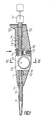
- the pipette according to the invention contains a housing 1 (FIG. 1) which has an upper part 2 and a lower part 3, on which exchangeable conical end pieces 4 are placed.
- the conical lower part 3 of the housing 1 can be designed as separable from the remaining part of the housing 1 and have a different length depending on the need.
- the housing 1 of the pipette has an internal cavity in which a piston 5 is movably installed with a rod 6, the upper end of which protrudes over the upper part 2 of the pipette housing. On . the outstanding end of the rod 6, a push button 7 is attached.
- the piston 5 and the rod 6 can be designed in the form of a plunger which has the same cross section in its entire longitudinal direction, as shown in FIG. 1, or can have a different diameter at different points along its length.
- a regulating bushing 8 (FIG. 2) is arranged on the rod 6, which enables to move in the longitudinal direction and which has an external thread.
- the regulating bushing 8 is fixed in the housing 1 against rotation about the axis.
- the socket 8 may have longitudinal flats on three sides, at an angle of 90 ° to one another, while the cavity in the housing 1 is designed with a rectangular cross-section and dimensions which secure the longitudinal displacement of the socket 8 without play around the axis.
- a spring 10 (FIG. 1) for returning the rod 6 is arranged under the stop 9 on the rod 6, cushioning the rod 6 with respect to the housing 1 on the part of its lower part 3 until the stop 9 contacts the socket 8.
- an adjusting nut 11 (FIGS. 1, 2) is arranged, with the possibility of its inevitable displacement in the transverse direction to the axis of the piston 6.
- the nut 11 can, as intended, assume two positions, in one of which it is is in toothing with the thread of the regulating bush 8, and in the other, where it emerges from the toothing.
- the bushing 8 is held in the first position by the nut 11 from longitudinal displacements, and in the second position it is given the opportunity to move independently of the nut 11.
- longitudinal displacements can be communicated to the socket by rotating nut 11.
- the pipette has a device for visual dose reading, designed in the form of the gear wheel 12 (FIGS. 2, 3), which is in constant toothing with the socket 8 and is kinematically connected to the circular scale 13 and the reading mark 14 (FIG. 1).
- the verb tion between socket 8 (Fig. 2, 3), gear 12 and scale 13 with reading mark 14 (Fig. 1) is designed so that the mutual position of the scale 13 and mark 14 clearly by the position of socket 8 in the housing 1 of Pipette is intended.
- the opening in the nut 11 can be made larger than the maximum dimension of the cross section of bushing $.
- the nut 11 can be installed with the possibility of a rotation in ring 15 (FIG. 2), which displaces the nut 11 in the transverse direction to the axis of Rod 6 aligns.
- the ring 15 can be designed, for example, either as a part apart from the housing 1, or as a special bearing eye in the housing 1, in which the nut 11 is installed.
- the nut 11 is cushioned with respect to the housing 1 in the transverse direction to the axis of rod 6 by the spring 16, which acts on the nut 11, for example via the movable ring 15.
- the effect of spring 16 on nut 11 via ring 1 ensures the interlocking of the thread of nut 11 with the thread of bushing 8 in the first position of nut 11.
- m can be moved to the nut 1 1 in the transverse direction so that it emerges from the toothing with bushing 8, which means the second position.
- the design provides such dimensions and shape of the ring 15 and the portion in the housing 1, so that the second position of the nut 11 would have been reached by pressing on the nut 11 (or on the ring 15) in the transverse direction up to the stop, while the direction transverse displacement would be the only possible.
- bushing 8 is given the possibility of a longitudinal displacement independently of nut 11, but remains connected to the device for. visual adjustment of the dose.
- a mechanical bond can be created between the position of bush 8 and the position of rod 6, where the nut is in the second position.
- This allows the longitudinal position of the bushing 8 to be controlled by means of the push button 7.
- the spring 17 is arranged, which cushions the bushing 8 with respect to the housing 1 on the part of its upper part.
- bushing 8 proves to be pressed against the stop 9 of the rod in any position.
- the bushing 8 can be given any position from the possible in the longitudinal direction, thereby setting the limits of the movement of the piston 5 (FIG. 1), and with the aid of the reading device of the cans , determine the set size of the dose.
- the adjusting nut 11 can be provided with a cylindrical scale 18 (FIG. 4) for precise dose reading. If the scale value of the round scale 13 (FIG. 2) is a multiple of a rotation of the nut 11 about the axis, a constant connection between the displays of the round scale 13 and the cylindrical scale 18 (FIG. 4) is maintained with any displacements of the regulating bushing 8 .
- the regulating bushing 8 (FIG. 2) on the section of the toothing with nut 11 in the form of a thread, and on the section of the toothing with the gearwheel 12 in the form of a toothed bar.
- the mutual position of nut 11 and gear 12 in the housing 1 of the pipette is such that, in any position of the socket 8, the nut 11 can only be toothed with the thread and the gear 12 can only be toothed with the toothed strip.
- the circular scale 13 (FIG. 3) can be arranged on the end face of the gear wheel 12.
- the gear wheel 12 can be designed with the scale 13 in the form of a part and built into the bearing eye of the housing 1-j, which is covered by a transparent cover 19 from the side of the scale, and in the same plane with the surface of the housing, immovable to it, is arranged.
- the reading mark of the round scale can be placed on the cover 19.
- the gear 12 can with respect to the housing by a spiral spring (not shown in the drawings) in the direction of its rotation to be cushioned around the axis.
- a mechanism of the intermediate stop can be considered in the pipette according to the invention which, when the dose is being displaced, allows the piston 5 (FIG. 1) to be additionally displaced, which is also necessary and for removing the Dose is strictly given.
- a mechanism can be implemented, for example, in the form of a bush 20 (FIG. 1, 2) of the intermediate stop and a spring 21, which cushion the bush 20 upwards with respect to the housing 1 up to the stop on the upper part 2 of the housing.
- the upper end face of the socket 20 protrudes above the upper part 2 of the housing.
- the pressure force of spring 21 is such that when button 7 strikes the end face of socket 20, a clearly noticeable change in the resistance to further adjustment of button 7 is created.
- the interchangeable end piece 4 is placed on the conical lower part.
- the button 7 is pressed again, in order to ensure a complete displacement of the dose, one pushes beyond the intermediate position by overcoming the additional pressure of the spring 21 of the intermediate stop.
- the readjustment of the dose size can be carried out gradually in the pipette according to the invention as well as in other pipettes. Transition across the entire can range.
- the adjusting nut 11 has to be turned, passing all intermediate quantities of the dose (observing the information from the reading device).
- the rotation of the nut 11, which is meshed with the bushing 8 forces the bushing 8 to shift in the longitudinal direction into a new position, which determines the new dose size.
- To reset a dose size that differs greatly from the first one it is necessary to carry out a large number of rotations of the adjusting nut 11, which is time-consuming. With repeated readjustments, the necessity of which often arises in laboratory practice, this time is long overall, and the manipulations to readjust the dose size are exhausting.
- the bush 8 engages again with the nut 11 and when the button 7 is subsequently pressed, it correspondingly limits the gear of the rod 6 and piston 5 without changing the set position.
- the bushing 8 shifts in a small range in the longitudinal direction, limiting the range of displacement of the rod 6 with the required accuracy.
- the reading device in the pipette according to the invention is of a simpler design than in other known pipettes, with gradual coverage of the metering range, which allows the device to be made lighter and smaller in size.
Landscapes
- Health & Medical Sciences (AREA)
- Clinical Laboratory Science (AREA)
- Chemical & Material Sciences (AREA)
- Chemical Kinetics & Catalysis (AREA)
- Devices For Use In Laboratory Experiments (AREA)
- Nitrogen And Oxygen Or Sulfur-Condensed Heterocyclic Ring Systems (AREA)
- Sampling And Sample Adjustment (AREA)
Abstract
Une pipette permettant de varier rapidement le volume dosé comporte un boîtier (1) dans lequel sont montés un piston mobile (5) et une tige (6). Un manchon de réglage (8) relié à un dispositif permettant la lecture de la dose sert au réglage de la longueur de la course du piston ainsi qu'au réglage du volume dosé. La position du manchon (8) est choisie au moyen d'un écrou (11) de réglage, et dans le cas où l'écrou (11) est dissocié du manchon (8) - au moyen d'un bouton fixé à la partie supérieure de la tige.
Applications Claiming Priority (1)
| Application Number | Priority Date | Filing Date | Title |
|---|---|---|---|
| PCT/SU1986/000096 WO1988002277A1 (fr) | 1986-09-29 | 1986-09-29 | Pipette |
Publications (2)
| Publication Number | Publication Date |
|---|---|
| EP0286676A1 true EP0286676A1 (fr) | 1988-10-19 |
| EP0286676A4 EP0286676A4 (fr) | 1989-10-16 |
Family
ID=21617039
Family Applications (1)
| Application Number | Title | Priority Date | Filing Date |
|---|---|---|---|
| EP19860907019 Withdrawn EP0286676A4 (fr) | 1986-09-29 | 1986-09-29 | Pipette. |
Country Status (6)
| Country | Link |
|---|---|
| EP (1) | EP0286676A4 (fr) |
| JP (1) | JPH01500971A (fr) |
| AU (1) | AU582486B2 (fr) |
| DK (1) | DK284488A (fr) |
| FI (1) | FI882357A0 (fr) |
| WO (1) | WO1988002277A1 (fr) |
Cited By (2)
| Publication number | Priority date | Publication date | Assignee | Title |
|---|---|---|---|---|
| DE4335863C1 (de) * | 1993-10-21 | 1995-02-02 | Eppendorf Geraetebau Netheler | Kolbenhubpipette |
| US6910395B2 (en) | 2002-08-17 | 2005-06-28 | Eppendorf Ag | Pipetting device |
Families Citing this family (1)
| Publication number | Priority date | Publication date | Assignee | Title |
|---|---|---|---|---|
| US7175813B2 (en) * | 2003-12-31 | 2007-02-13 | Rainin Instrument, Llc | Volume adjustable manual pipette with quick set volume adjustment |
Family Cites Families (6)
| Publication number | Priority date | Publication date | Assignee | Title |
|---|---|---|---|---|
| US3013435A (en) * | 1959-04-06 | 1961-12-19 | Microchemical Specialties Co | Buret |
| US3353718A (en) * | 1966-05-24 | 1967-11-21 | Fischer & Porter Co | Syringe, column or the like |
| US3494201A (en) * | 1968-08-16 | 1970-02-10 | Oxford Lab | Pipetting system |
| US4098125A (en) * | 1977-03-30 | 1978-07-04 | Lee Thomas E | Adjustable volume pipetting device |
| GB2029723B (en) * | 1978-09-12 | 1982-12-01 | Lee T | Adjustable volume pipetting device |
| SU1270572A1 (ru) * | 1984-08-22 | 1986-11-15 | Всесоюзный научно-исследовательский институт биологического приборостроения | Дозатор жидкости |
-
1986
- 1986-09-29 EP EP19860907019 patent/EP0286676A4/fr not_active Withdrawn
- 1986-09-29 JP JP62500024A patent/JPH01500971A/ja active Granted
- 1986-09-29 WO PCT/SU1986/000096 patent/WO1988002277A1/fr not_active Ceased
- 1986-09-29 AU AU67262/87A patent/AU582486B2/en not_active Ceased
- 1986-09-29 FI FI882357A patent/FI882357A0/fi not_active IP Right Cessation
-
1988
- 1988-05-25 DK DK284488A patent/DK284488A/da not_active Application Discontinuation
Cited By (4)
| Publication number | Priority date | Publication date | Assignee | Title |
|---|---|---|---|---|
| DE4335863C1 (de) * | 1993-10-21 | 1995-02-02 | Eppendorf Geraetebau Netheler | Kolbenhubpipette |
| EP0649678A1 (fr) * | 1993-10-21 | 1995-04-26 | Eppendorf-Netheler-Hinz Gmbh | Pipette à piston |
| US6910395B2 (en) | 2002-08-17 | 2005-06-28 | Eppendorf Ag | Pipetting device |
| DE10237770B4 (de) * | 2002-08-17 | 2006-11-09 | Eppendorf Ag | Pipettiervorrichtung |
Also Published As
| Publication number | Publication date |
|---|---|
| JPH0316178B2 (fr) | 1991-03-04 |
| FI882357L (fi) | 1988-05-19 |
| AU6726287A (en) | 1988-04-21 |
| EP0286676A4 (fr) | 1989-10-16 |
| FI882357A7 (fi) | 1988-05-19 |
| DK284488D0 (da) | 1988-05-25 |
| WO1988002277A1 (fr) | 1988-04-07 |
| DK284488A (da) | 1988-05-25 |
| FI882357A0 (fi) | 1988-05-19 |
| AU582486B2 (en) | 1989-03-23 |
| JPH01500971A (ja) | 1989-04-06 |
Similar Documents
| Publication | Publication Date | Title |
|---|---|---|
| DE2366404C2 (de) | Mehrfachpipette | |
| DE2857423C2 (fr) | ||
| DE3781762T2 (de) | Mehrkanal-pipette. | |
| EP0077897B2 (fr) | Presse pour fabriquer des articles pressés gardant la mesure à partir de matière pulvérulente | |
| DE2541642A1 (de) | Pipettier- und dosiergeraet | |
| EP0649678A1 (fr) | Pipette à piston | |
| EP0547503A1 (fr) | Dispositif pour pipetter | |
| DE2365947A1 (de) | Mit der hand zu haltende pipette | |
| DE2533686C3 (de) | Wechselschreibstift | |
| EP4406655A2 (fr) | Pipette pour utilisation avec une pointe ou une seringue comportant un piston et un cylindre | |
| DE10020591B4 (de) | Ausgabevorrichtung für viskoses Dentalmaterial | |
| DE2265611C2 (de) | Vorrichtung zum wählbaren Einstellen mehrerer Typenträger eines Stempels in einem Etikettenausgeber | |
| CH617362A5 (fr) | ||
| DE2930372C2 (de) | Pipettiervorrichtung mit einstellbarem Volumen | |
| DE19915771C1 (de) | System zum Aufnehmen und Abgeben von Fluidvolumina | |
| DE2825015C2 (de) | Flüssigkeitsausgabegerät | |
| DE2228864C3 (de) | Vorrichtung zur Anzeige des Verschmutzungsgrades von Gas- oder Flüssigkeitsfiltern | |
| DE4003591A1 (de) | Mehrkanalpipette mit neigungsspiel an der hubplatte aufweisenden kolben | |
| EP0286676A1 (fr) | Pipette | |
| DE3221438A1 (de) | Vorrichtung zum entnehmen einer bestimmten fluessigkeitsmenge aus einem behaelter | |
| AT394146B (de) | Vorrichtung zur ausgabe von in zwei voneinander getrennten behaeltern gelagerten substanzen | |
| EP0046461A1 (fr) | Dispositifs de dosage pour liquides ou gaz | |
| DE1773927B1 (de) | Vorrichtung zur aufzeichnung von relativbewegungen | |
| DE3137423A1 (de) | "mikroliterpipette" | |
| DE1291142B (de) | Vorrichtung zum exakten Abmessen und UEbertragen kleiner Fluessigkeitsmengen |
Legal Events
| Date | Code | Title | Description |
|---|---|---|---|
| PUAI | Public reference made under article 153(3) epc to a published international application that has entered the european phase |
Free format text: ORIGINAL CODE: 0009012 |
|
| 17P | Request for examination filed |
Effective date: 19880505 |
|
| AK | Designated contracting states |
Kind code of ref document: A1 Designated state(s): BE CH DE FR GB IT LI NL SE |
|
| A4 | Supplementary search report drawn up and despatched |
Effective date: 19891016 |
|
| 17Q | First examination report despatched |
Effective date: 19900924 |
|
| STAA | Information on the status of an ep patent application or granted ep patent |
Free format text: STATUS: THE APPLICATION HAS BEEN WITHDRAWN |
|
| 18W | Application withdrawn |
Withdrawal date: 19920306 |