EP0286725A1 - Unité de propulsion pour convoyeurs et méthode pour leur mise en service - Google Patents
Unité de propulsion pour convoyeurs et méthode pour leur mise en service Download PDFInfo
- Publication number
- EP0286725A1 EP0286725A1 EP87117431A EP87117431A EP0286725A1 EP 0286725 A1 EP0286725 A1 EP 0286725A1 EP 87117431 A EP87117431 A EP 87117431A EP 87117431 A EP87117431 A EP 87117431A EP 0286725 A1 EP0286725 A1 EP 0286725A1
- Authority
- EP
- European Patent Office
- Prior art keywords
- drive
- conveyor
- articles
- sequentially
- driving device
- Prior art date
- Legal status (The legal status is an assumption and is not a legal conclusion. Google has not performed a legal analysis and makes no representation as to the accuracy of the status listed.)
- Granted
Links
- 238000000034 method Methods 0.000 title claims abstract description 15
- 238000009825 accumulation Methods 0.000 claims abstract description 19
- 230000007246 mechanism Effects 0.000 claims abstract description 12
- 230000003213 activating effect Effects 0.000 claims description 19
- 230000000712 assembly Effects 0.000 claims description 9
- 238000000429 assembly Methods 0.000 claims description 9
- 238000012544 monitoring process Methods 0.000 claims 3
- 239000004677 Nylon Substances 0.000 claims 1
- 230000008878 coupling Effects 0.000 claims 1
- 238000010168 coupling process Methods 0.000 claims 1
- 238000005859 coupling reaction Methods 0.000 claims 1
- 229920001778 nylon Polymers 0.000 claims 1
- 230000007723 transport mechanism Effects 0.000 abstract description 4
- 230000008901 benefit Effects 0.000 description 2
- 230000001276 controlling effect Effects 0.000 description 2
- 230000007423 decrease Effects 0.000 description 2
- 230000007812 deficiency Effects 0.000 description 1
- 230000000994 depressogenic effect Effects 0.000 description 1
- 238000010586 diagram Methods 0.000 description 1
- 230000002708 enhancing effect Effects 0.000 description 1
- 230000005484 gravity Effects 0.000 description 1
- 230000003287 optical effect Effects 0.000 description 1
- 230000037361 pathway Effects 0.000 description 1
- 230000002035 prolonged effect Effects 0.000 description 1
- 230000001105 regulatory effect Effects 0.000 description 1
- 230000008439 repair process Effects 0.000 description 1
- 230000000717 retained effect Effects 0.000 description 1
- 238000012163 sequencing technique Methods 0.000 description 1
- 238000006467 substitution reaction Methods 0.000 description 1
- 239000013589 supplement Substances 0.000 description 1
Images



Classifications
-
- B—PERFORMING OPERATIONS; TRANSPORTING
- B65—CONVEYING; PACKING; STORING; HANDLING THIN OR FILAMENTARY MATERIAL
- B65G—TRANSPORT OR STORAGE DEVICES, e.g. CONVEYORS FOR LOADING OR TIPPING, SHOP CONVEYOR SYSTEMS OR PNEUMATIC TUBE CONVEYORS
- B65G47/00—Article or material-handling devices associated with conveyors; Methods employing such devices
- B65G47/22—Devices influencing the relative position or the attitude of articles during transit by conveyors
- B65G47/26—Devices influencing the relative position or the attitude of articles during transit by conveyors arranging the articles, e.g. varying spacing between individual articles
- B65G47/261—Accumulating articles
-
- B—PERFORMING OPERATIONS; TRANSPORTING
- B65—CONVEYING; PACKING; STORING; HANDLING THIN OR FILAMENTARY MATERIAL
- B65G—TRANSPORT OR STORAGE DEVICES, e.g. CONVEYORS FOR LOADING OR TIPPING, SHOP CONVEYOR SYSTEMS OR PNEUMATIC TUBE CONVEYORS
- B65G13/00—Roller-ways
- B65G13/02—Roller-ways having driven rollers
- B65G13/06—Roller driving means
-
- B—PERFORMING OPERATIONS; TRANSPORTING
- B65—CONVEYING; PACKING; STORING; HANDLING THIN OR FILAMENTARY MATERIAL
- B65G—TRANSPORT OR STORAGE DEVICES, e.g. CONVEYORS FOR LOADING OR TIPPING, SHOP CONVEYOR SYSTEMS OR PNEUMATIC TUBE CONVEYORS
- B65G43/00—Control devices, e.g. for safety, warning or fault-correcting
- B65G43/08—Control devices operated by article or material being fed, conveyed or discharged
-
- B—PERFORMING OPERATIONS; TRANSPORTING
- B65—CONVEYING; PACKING; STORING; HANDLING THIN OR FILAMENTARY MATERIAL
- B65G—TRANSPORT OR STORAGE DEVICES, e.g. CONVEYORS FOR LOADING OR TIPPING, SHOP CONVEYOR SYSTEMS OR PNEUMATIC TUBE CONVEYORS
- B65G2203/00—Indexing code relating to control or detection of the articles or the load carriers during conveying
- B65G2203/04—Detection means
- B65G2203/042—Sensors
-
- B—PERFORMING OPERATIONS; TRANSPORTING
- B65—CONVEYING; PACKING; STORING; HANDLING THIN OR FILAMENTARY MATERIAL
- B65G—TRANSPORT OR STORAGE DEVICES, e.g. CONVEYORS FOR LOADING OR TIPPING, SHOP CONVEYOR SYSTEMS OR PNEUMATIC TUBE CONVEYORS
- B65G2203/00—Indexing code relating to control or detection of the articles or the load carriers during conveying
- B65G2203/04—Detection means
- B65G2203/042—Sensors
- B65G2203/044—Optical
Definitions
- This invention relates to transfer mechanisms and, more particularly, this invention relates to a transfer mechanism for transporting containers and an improved conveyor drive unit therefor.
- the instant invention relates to the automatic and sequential starting and stopping of a plurality of drive units relative to a predetermined parameter of the flow of articles along the transfer mechanism.
- Cowen The activating mechanism in Cowen is not however directly controlled by the articles being transported thereby increasing the chance of halting a specific roller when not desired. Moreover, Cowen uses a spring activating device which is cumbersome to maintain or repair. Further, due to an indirect control by the articles, relieving of pressure due to article accumulation is inefficient.
- U.S. Patent No. 4,313,536 issued on February 2, 1982 to Frederick E. Fauth, Sr. provides significant improvements over the use of chains.
- U.S. Patent No. 4,313,536 provides a significant feature of providing separate drive systems in order to obtain flexibility in the movement of articles.
- the present invention is a device for significantly improving a conveyor system like U.S. Patent No. 4,313,536 which is embodied herein in its entirety by reference. It is in this separate drive unit, as in U.S. Patent No. 4,313,536, which when added to a roller-type conveyor system contributes to the significant advantage of being able to automatically control various portions of the conveyor system.
- the system of U.S. Patent No. 4,313,536 does not provide for "zero pressure" accumulation.
- zero pressure accumulation is meant accumulation of articles without any significant pressure being applied thereto by the mass of articles being accumulated.
- the drive unit used in the present invention satisfies such a need.
- the drive unit of the instant invention embodies a simply constructed combination of inexpensive, easily accessible and rapidly manufactured parts, yet efficient when used in an article transfer system in providing a true "zero pressure" (i.e., absence of pressure applied by the articles to abutting articles during accumulation).
- the improved conveyor drive unit is used in a transport system having a plurality of transport mechanisms or modules.
- Each module has a plurality of rollers arranged in a planar array, the drive units and means for connecting the drive units with the rollers.
- Each drive unit drives a plurality of rollers.
- the automatic means is responsive to a predetermined parameter in the flow of the articles along the transport system.
- an improved conveyor drive unit for rapid and easy mounting on a roller-type conveyor system.
- an arm extends at a desired distance over an article path.
- a pivoted end of the arm is operably attached to a pneumatic or air valve.
- When article accumulation occurs, at least one article displaces the free end of the arm which then trips the pneumatic valve to release air into an actuator cylinder having operably coupled thereto a shifter rod.
- the shifter rod is axially displaced by the actuating cylinder which in turn releases a drive collar from a keyed sprocket of the pinion gears of a transport mechanism or "module" of the conveyor system.
- the drive collar is disengaged, the operation of transfer mechanism or module is halted.
- a set of sensors are positioned along the accumulation area of the conveyor path which can activate a series of solenoid valves which in turn sequentially operate and control the drive units.
- a set of counting or timing devices are positioned along the in-feed portion of the conveyor path, instead of the just-mentioned set of sensors, for sequentially operating and controlling the drive units relative to the number or speed of the articles being transported along the conveyor path.
- a programmable controller be operably coupled to the solenoid valves and the actuator cylinders for enhancing the sequential operation of the drive units.
- Figure 1 shows a transfer mechanism or "module”, generally designated by reference number 1, of the conveyor system described in the above-discussed U.S. Patent No. 4,313,536.
- the “module” 1 is driven by a motor 5 having a sprocket wheel 8 which is connected to another sprocket wheel 12 through chain 10.
- One side of the sprocket wheel 12 bears against a fixed thrust washer 11.
- Another thrust washer 16 is biased against the other side of sprocket wheel 12 by spring 13.
- the thrust washers 11 and 16 are both fixed to a drive shaft 14 against relative rotation.
- One of the thrust washers is, however, arranged to be axially movable.
- the drive shaft 14 is directly coupled to a drive assembly, generally referred to by reference numeral 15.
- the drive assembly 15 has a plurality of pinion gears 18 which receive the rotation of the sprocket wheel 12 through the thrust washers 11 and 16 and drive shaft 14. The pinion gears 18 then rotate flexible shafts 20 which connect with the planar array of rollers 22 mounted on bearing members 24, 26.
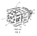
- FIG. 2 shows in more detail the various elements operating in drive assembly 15.
- Each of the pinion gears 18 is fixed to a pinion shaft 28.
- a flexible shaft 20 is fitted into each pinion shaft 28.
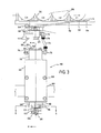
- FIG. 3 shows the improved drive assembly of one embodiment of the instant invention, generally designated by reference numeral 50.
- the improved drive assembly 50 can be used in the above-described "module" 1 in place of the drive assembly of the prior art, although it is not limited thereto.
- the improved drive assembly 5u has an actuating arm 52 which sufficiently extends beyond the boundary line 54 of a path 56 travelled by articles 58 being transported on a system similar to the above-described planar array of rollers 22 which could be a conveyor, an accumulation table, or the like.
- the actuating arm 52 has a pivoted end portion 62 and a free end portion 60 which extends between the path 56 and an actuating button 66 of a pneumatic valve 68 which is connected to an air supply device.
- Free end 60 of the actuating arm 52 can be deflected by at least one of the articles 58, preferably when the articles 58 accumulate in a pattern.
- the pivoted end 62 of the actuating arm 52 is retained by a pivot block 64.
- the actuating button 66 is resiliently disposed, preferably by a spring-like member (not shown), in the pneumatic valve 68 to a normally extended position so that the actuating arm 52 against which the actuating button 66 bears is returned to its original position after accumulation of the articles 58 is relieved.
- an air inlet 67 from the air supply can be successively joined to a plurality of pneumatic valves 68.
- the pneumatic valve 68 which is conventionally manufactured, e.g., by Clippard Co., has an outlet tube 70 which connects to an intermediate tube 72 by a conventional fastening bolt 74.
- the intermediate tube 72 is in turn connected to an external tube 76 of an actuator cylinder 78 preferably fastened in a similar manner.
- the actuator cylinder 78 has an air release valve 79 which can be adjusted to maintain the desired air pressure inside the actuator cylinder 78 and relieve the pressure when the pneumatic valve 68 is closed.
- the actuator cylinder 78 is mounted on an actuator support member 80 preferably by at least one bolt 82 having a head 83 with a washer 84 abutting a back plate 85 in order to prevent excessive load on the actuator support member 80 when the bolt is fastened.
- the actuator support member 80 which can be a housing if desired, mounts above a drive assembly 15 or the like, modified according to the present invention, by means of a plurality of nut and bolt combinations 88 in a manner which will later be discussed.
- the lower portion of the drive assembly 15, or the like is preferably mounted on a fixed plate assembly 90 located proximately adjacent the conveyor path 56.
- a shifter rod 92 which is also mounted below the actuator support member 80 extends above a keyed sprocket 94 having a sprocket wheel 96, preferably integral thereto.
- a threaded end 98 of the shifter rod 92 accommodates a shifter member 100 between at least a pair of nuts 101, 102.
- the shifter member 100 is seated in an annular groove 154 (see Figure 6b) in a drive collar 102 which is attached to the drive shaft 14 by a drive pin 104.
- the pin 104 extends through an aperture 106 passing through the drive shaft 14 and is accommodated within a space 108 at the outer end portion of the drive collar 102.
- the drive collar 102 has an aperture llo passing therethrough which accommodates the drive shaft 14.
- the inner end of the drive collar 102 has a lateral protruding portion 112 which is inserted into a slit portion 114 of the sprocket wheel 96.
- a ring washer 116 is placed between the drive collar 102 and the sprocket wheel 96 for proper seating thereto.
- a retainer ring 120 At the inner end portion of the sprocket wheel 96 is a retainer ring 120, such as a "True Arc" or “Ramsey”-type retainer ring, which can be snugly fitted into a groove (not shown) along the circumference of the drive shaft 14.
- the plunger 122 has a seal washer 124 being accommodated by a groove 126 thereof.
- the shifter rod 92 has stoppers 128, 130 which are coupled thereto, in an adjustable manner with the use of externally adjustable threaded members 132, 134, respectively. Stopper 128 abuts the inner portion of the actuator support member 80 when the end portion 136 is inside the actuator cylinder 78. Stopper 130 abuts a spring 138 which normally deflects the end portion 136 inside the actuator cylinder 78 when air is not supplied thereto.
- the end portion 136 is thereby used to deflect the plunger 122 when air inside the actuator cylinder 78 escapes through the air release valve 79 which is regulated to provide a desired internal pressure in the actuator cylinder 78.
- the spring 138 further abuts against a support bracket 140.
- the support bracket 140, as well as another support bracket 142, have apertures 146, 148, respectively, passing therethrough for accommodating and supporting the length of the shifter rod 92.
- the support brackets 140, 142 are preferably L-shaped in order to be able to mount the actuator support member 80 onto a drive assembly 150 which may be similar to the drive assembly 15, previously discussed.
- the shifter member 100 causes the drive collar 102 to disengage from the sprocket wheel 96.
- the sprocket wheel 96 is then free to rotate relative to the drive shaft 14, that is, to "free wheel”.
- the actuating arm 52 When the accumulation of articles 58 is relieved, the actuating arm 52 is deflected back to its original position by the spring-loaded actuating button 66 which in turn permits the plunger 122 of the actuator cylinder 78 to be withdrawn. Consequently, the end portion 136 of the shifter rod 92 is shifted and deflected towards the plunger 122. The shifting or deflection of the shifting rod 92 then causes the drive collar 102 to engage the sprocket wheel 96, in a manner more fully discussed below, thereby rotating the drive shaft 14.
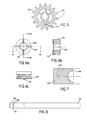
- Figure 5 illustrates a plurality of teeth 152 surrounding the sprocket wheel 96 having a centrally located slit portion 114 for accommodating the lateral protruding portion 112 of the drive collar 102 during engagement.
- Figure 6a shows the drive collar 102 having the lateral protruding portion 112.
- Figures 6b and 6c are further illustrations of the drive collar 102 having the preferably integral protruding portion 112 suitable for being keyed or inserted in the slit portion 114 of the sprocket wheel 96 during engagement the drive collar 102. Further shown in Figure 6b is the space 108 for accommodating the pin 104 which connects the drive collar 102 to the drive shaft 14.
- the shifter member 100 Shown in Figure 7 is the shifter member 100 which has a preferably concavely semi-circular end portion 156 which allows the shifter member 100 to abut against the drive collar 102 through the groove portion 154.
- the shifter member 100 also has an aperture 158 passing therethrough for accommodating the shifter rod 92.
- Figure 8 illustrates the actuating arm 52 which has the pivoted end 62 preferably configured like a cylinder 160 having an aperture 162 passing therethrough.
- the cylinder 160 is preferably freely bolted onto the pivot block 64.
- actuating arm 52 instead of using an actuating arm 52, as described above, other types of actuating means, not limited to a mechanical version, can be used.
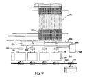
- FIG 9 there is shown a partial schematic or diagrammatic view of a plurality of the transport mechanisms having a series of drive assemblies 50 of the present invention is shown with a plurality of sensors 180, such as optical or electrical devices, all well-known in the art, preferably located adjacent the accumulation area of the path 56 travelled by the articles 58 (i.e., along the conveyor or accumulation table similar to the above-described planar array of rollers 22).
- Connecting means such as wires 183 operatively connect each of the sensors 180 to an input portion 185 of a programmable controller (PC) 188.
- An output portion 190 of the PC 188 is operatively connected to a plurality of solenoid valves 192 by connecting means such as wires 194.
- PC programmable controller
- one of solenoid valves 192 is operably connected to the actuator cylinder 78 of each drive assembly 150.
- the series of sensors 180 in conjunction with the PC 188 and the solenoid valves 192, permit the sequential stopping and re-starting of the drive assemblies 150.
- the drive assemblies 150 are re-started when the sensors 180 indicate that normal article flow is to be resumed.
- the sensors 180 are connected to the input portion 185 of the PC 188, although certain sensors 180 may have built-in time delay characteristics which may warrant the removal of the PC 188 and have the sensors 180 directly connected to the solenoid valves 192.
- the PC 188 will significantly enhance the sequencing operation of the drive assemblies 150.
- Programmable controllers are well-known in the art and are commercially available. Those skilled in the art are aware of the mode of pre-setting the controllers to provide an output signal to means such as solenoid valves 192 responsive to signals received from means such as sensors 180.
- Figure 9 shows a sensor 180 for each solenoid valve 192, this arrangement is not meant to limit the scope of the instant invention. A single sensor or a prescribed number thereof can be inputted into the PC 188 having the output portion 190 thereof connected to the series of solenoid valves 192.
- solenoid valves can be ganged as shown in Figure 10, which illustrates a 3-way 2-position type solenoid valve 200, manufactured, for example, by C.A. Norgren Co.
- the solenoid valve 200 has at least three air passages 203, each passage to be connected to at least one actuator cylinder 78. Further, the solenoid valve 200 has at least three terminals 206 for connecting with the PC 188.
- At a manifold portion 209 are air inlet 212 and outlet passages 215. The air inlet 212 is connected to the air supply.
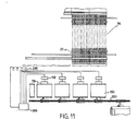
- FIG 11 a similar type of arrangement as discussed in Figure 9, is shown, except for the substitution of the plurality of sensors 192 with a plurality of counting or timing devices 218 connected to the PC 188. Further, the counting or timing devices 218 are located at the in-feed portion of the accumulation area of the conveyor path 56.
- the drive assemblies 150 are preferably arranged side-by-side as shown.
- the improved drive assemblies 150 with the above-discussed mechanical actuating arms 52 are similarly arranged.
- Figure 12 shows the arrangement wherein the series of sprocket wheels 96 are operated by a single chain 230 being driven by end sprockets 233. At least one of the end sprockets 233 is driven by a drive means such as a motor 235 with chain 238. n order to conserve space, each end sprocket 233 can be positioned below and between one of the end sprocket wheels 240 and the immediately adjacent sprocket wheel 245 in order to form a more compact arrangement.
- sprocket wheel 245 will have at least two sets of teeth, one set of teeth for connecting with the end sprocket 240 by a chain (not shown) different from chain 230 and another set of teeth for connecting with chain 230. It should be understood that while sprocket wheels and chains have been described as providing the primary driving force, any equivalent driving means could be used.
Landscapes
- Engineering & Computer Science (AREA)
- Mechanical Engineering (AREA)
- Rollers For Roller Conveyors For Transfer (AREA)
- Control Of Conveyors (AREA)
Applications Claiming Priority (2)
| Application Number | Priority Date | Filing Date | Title |
|---|---|---|---|
| US35374 | 1987-04-08 | ||
| US07/035,374 US4828103A (en) | 1987-04-08 | 1987-04-08 | Conveyor drive unit and method for operation thereof |
Publications (2)
| Publication Number | Publication Date |
|---|---|
| EP0286725A1 true EP0286725A1 (fr) | 1988-10-19 |
| EP0286725B1 EP0286725B1 (fr) | 1991-09-04 |
Family
ID=21882291
Family Applications (1)
| Application Number | Title | Priority Date | Filing Date |
|---|---|---|---|
| EP87117431A Expired EP0286725B1 (fr) | 1987-04-08 | 1987-11-26 | Unité de propulsion pour convoyeurs et méthode pour leur mise en service |
Country Status (5)
| Country | Link |
|---|---|
| US (1) | US4828103A (fr) |
| EP (1) | EP0286725B1 (fr) |
| AU (1) | AU597539B2 (fr) |
| CA (1) | CA1283619C (fr) |
| DE (1) | DE3772753D1 (fr) |
Cited By (1)
| Publication number | Priority date | Publication date | Assignee | Title |
|---|---|---|---|---|
| CN109552818A (zh) * | 2017-09-26 | 2019-04-02 | Ica公司 | 应用密闭容器用卸压阀的机器和方法 |
Families Citing this family (5)
| Publication number | Priority date | Publication date | Assignee | Title |
|---|---|---|---|---|
| ITMI20051413A1 (it) * | 2005-07-22 | 2007-01-23 | Danieli Off Mecc | Dispositivo di azionamento rulli di macchine per la lavorazione di prodotti metallici |
| US8157083B2 (en) * | 2009-12-23 | 2012-04-17 | Laitran, L.L.C. | Self-clearing conveyor transfer system and transfer plate |
| US10308440B2 (en) * | 2017-10-23 | 2019-06-04 | Caterpillar Paving Products Inc. | System and method for managing speed of cold planer conveyor belt |
| CN114655724A (zh) * | 2022-03-08 | 2022-06-24 | 深圳市步先包装机械有限公司 | 一种运输箱的自动上料机构、方法及运输箱 |
| CN114560258B (zh) * | 2022-03-11 | 2022-12-02 | 淮南矿业(集团)有限责任公司 | 一种带式输送机保护装置 |
Citations (3)
| Publication number | Priority date | Publication date | Assignee | Title |
|---|---|---|---|---|
| GB1150974A (en) * | 1966-10-20 | 1969-05-07 | Rapistan Inc | Improvements in and relating to Conveyors |
| US4240538A (en) * | 1977-12-27 | 1980-12-23 | Harris Corporation | Method and apparatus for accumulating and gating articles |
| US4313536A (en) * | 1980-03-21 | 1982-02-02 | American Bottlers Equipment Co., Inc. | Conveyor and control therefor |
Family Cites Families (8)
| Publication number | Priority date | Publication date | Assignee | Title |
|---|---|---|---|---|
| US3782515A (en) * | 1968-01-17 | 1974-01-01 | United Ind Eng Corp | Shaft driver device and conveyor system embodying the same |
| DE2519374C2 (de) * | 1975-04-30 | 1986-01-09 | Interroll-Fördertechnik GmbH & Co KG, 5632 Wermelskirchen | Abschaltbare Treibrolle für Rollenförderbahnen |
| US4164998A (en) * | 1977-02-16 | 1979-08-21 | David A. DeGood | Accumulation live roller conveyor |
| AU5786880A (en) * | 1979-05-14 | 1980-11-20 | Dexion-Comino International Ltd. | Roller conveyors |
| US4453627A (en) * | 1980-02-08 | 1984-06-12 | The E. W. Buschman Co. | Accumulator conveyor |
| AT381080B (de) * | 1981-06-10 | 1986-08-25 | Amon Gerhard Ing | Staurollenbahn |
| US4570780A (en) * | 1982-05-13 | 1986-02-18 | Contran Conveyors & Systems, Inc. | Propelling and braking apparatus for a zero pressure accumulator |
| US4488638A (en) * | 1982-05-27 | 1984-12-18 | Figgie International Inc. | Live roller accumulating brake conveyor |
-
1987
- 1987-04-08 US US07/035,374 patent/US4828103A/en not_active Expired - Lifetime
- 1987-11-26 DE DE8787117431T patent/DE3772753D1/de not_active Expired - Fee Related
- 1987-11-26 EP EP87117431A patent/EP0286725B1/fr not_active Expired
- 1987-11-27 CA CA000552988A patent/CA1283619C/fr not_active Expired - Fee Related
- 1987-12-04 AU AU82086/87A patent/AU597539B2/en not_active Ceased
Patent Citations (3)
| Publication number | Priority date | Publication date | Assignee | Title |
|---|---|---|---|---|
| GB1150974A (en) * | 1966-10-20 | 1969-05-07 | Rapistan Inc | Improvements in and relating to Conveyors |
| US4240538A (en) * | 1977-12-27 | 1980-12-23 | Harris Corporation | Method and apparatus for accumulating and gating articles |
| US4313536A (en) * | 1980-03-21 | 1982-02-02 | American Bottlers Equipment Co., Inc. | Conveyor and control therefor |
Cited By (1)
| Publication number | Priority date | Publication date | Assignee | Title |
|---|---|---|---|---|
| CN109552818A (zh) * | 2017-09-26 | 2019-04-02 | Ica公司 | 应用密闭容器用卸压阀的机器和方法 |
Also Published As
| Publication number | Publication date |
|---|---|
| CA1283619C (fr) | 1991-04-30 |
| DE3772753D1 (de) | 1991-10-10 |
| US4828103A (en) | 1989-05-09 |
| EP0286725B1 (fr) | 1991-09-04 |
| AU8208687A (en) | 1988-10-13 |
| AU597539B2 (en) | 1990-05-31 |
Similar Documents
| Publication | Publication Date | Title |
|---|---|---|
| US4096942A (en) | Roller type of conveyor | |
| US5042644A (en) | Zero pressure accumulation conveyor and trigger assembly | |
| EP0286725B1 (fr) | Unité de propulsion pour convoyeurs et méthode pour leur mise en service | |
| CA1068233A (fr) | Transporteur accumulateur a galets moteurs | |
| US3513960A (en) | Accumulator conveyor | |
| US4406360A (en) | Accumulating conveyer | |
| US4819788A (en) | Zero pressure accumulation conveyor and brake assembly | |
| US4951808A (en) | Accumulating conveyor | |
| US4301914A (en) | Accumulating conveyor | |
| US4356900A (en) | Drive system | |
| US5076420A (en) | Clutch assembly for a zoned live conveyor | |
| US4630712A (en) | Automatic chain lubricating system | |
| SE466749B (sv) | Arkmatningsanordning | |
| JP3538455B2 (ja) | フイルタロッドを貯蔵部から空圧により移送が行われる導管内へ移送するための装置 | |
| IE890370A1 (en) | Improvements relating to bale wrapping machines | |
| JPH05116722A (ja) | ローラコンベア | |
| US4752000A (en) | Roller type conveyor with roller drive mechanism | |
| US3952864A (en) | Conveyor safety device | |
| GB2113638A (en) | Zero pressure accumulation conveyor and article sensing assembly | |
| GB2114084A (en) | Zero pressure accumulation conveyor and brake assembly | |
| US3561584A (en) | Apparatus for feeding pulpwood to a conveyor of a device for charging defiber magazines | |
| EP0291105B1 (fr) | Convoyeur à rouleaux à accumulation et rouleau entraîneur à cet effet | |
| KR20000056794A (ko) | 컨베이어 | |
| KR890003079B1 (ko) | 밴드의 공급 및 조임장치 및 그의 방법 | |
| EP0034131A1 (fr) | Un rouleau entraîné avec un mécanisme de débrayage, notamment pour convoyeurs à accumulation |
Legal Events
| Date | Code | Title | Description |
|---|---|---|---|
| PUAI | Public reference made under article 153(3) epc to a published international application that has entered the european phase |
Free format text: ORIGINAL CODE: 0009012 |
|
| AK | Designated contracting states |
Kind code of ref document: A1 Designated state(s): DE FR GB IT |
|
| 17P | Request for examination filed |
Effective date: 19890118 |
|
| 17Q | First examination report despatched |
Effective date: 19900621 |
|
| ITF | It: translation for a ep patent filed | ||
| GRAA | (expected) grant |
Free format text: ORIGINAL CODE: 0009210 |
|
| AK | Designated contracting states |
Kind code of ref document: B1 Designated state(s): DE FR GB IT |
|
| REF | Corresponds to: |
Ref document number: 3772753 Country of ref document: DE Date of ref document: 19911010 |
|
| ET | Fr: translation filed | ||
| PLBE | No opposition filed within time limit |
Free format text: ORIGINAL CODE: 0009261 |
|
| STAA | Information on the status of an ep patent application or granted ep patent |
Free format text: STATUS: NO OPPOSITION FILED WITHIN TIME LIMIT |
|
| 26N | No opposition filed | ||
| PGFP | Annual fee paid to national office [announced via postgrant information from national office to epo] |
Ref country code: GB Payment date: 19931116 Year of fee payment: 7 |
|
| PGFP | Annual fee paid to national office [announced via postgrant information from national office to epo] |
Ref country code: DE Payment date: 19931123 Year of fee payment: 7 |
|
| PGFP | Annual fee paid to national office [announced via postgrant information from national office to epo] |
Ref country code: FR Payment date: 19931124 Year of fee payment: 7 |
|
| PG25 | Lapsed in a contracting state [announced via postgrant information from national office to epo] |
Ref country code: GB Effective date: 19941126 |
|
| GBPC | Gb: european patent ceased through non-payment of renewal fee |
Effective date: 19941126 |
|
| PG25 | Lapsed in a contracting state [announced via postgrant information from national office to epo] |
Ref country code: FR Effective date: 19950731 |
|
| PG25 | Lapsed in a contracting state [announced via postgrant information from national office to epo] |
Ref country code: DE Effective date: 19950801 |
|
| REG | Reference to a national code |
Ref country code: FR Ref legal event code: ST |
|
| PG25 | Lapsed in a contracting state [announced via postgrant information from national office to epo] |
Ref country code: IT Free format text: LAPSE BECAUSE OF NON-PAYMENT OF DUE FEES;WARNING: LAPSES OF ITALIAN PATENTS WITH EFFECTIVE DATE BEFORE 2007 MAY HAVE OCCURRED AT ANY TIME BEFORE 2007. THE CORRECT EFFECTIVE DATE MAY BE DIFFERENT FROM THE ONE RECORDED. Effective date: 20051126 |