EP0286863A2 - Bodenrinnenprofil für eine Bodenablaufrinne - Google Patents
Bodenrinnenprofil für eine Bodenablaufrinne Download PDFInfo
- Publication number
- EP0286863A2 EP0286863A2 EP88104314A EP88104314A EP0286863A2 EP 0286863 A2 EP0286863 A2 EP 0286863A2 EP 88104314 A EP88104314 A EP 88104314A EP 88104314 A EP88104314 A EP 88104314A EP 0286863 A2 EP0286863 A2 EP 0286863A2
- Authority
- EP
- European Patent Office
- Prior art keywords
- profile
- floor
- channel
- joint
- gutter
- Prior art date
- Legal status (The legal status is an assumption and is not a legal conclusion. Google has not performed a legal analysis and makes no representation as to the accuracy of the status listed.)
- Granted
Links
Images

Classifications
-
- E—FIXED CONSTRUCTIONS
- E04—BUILDING
- E04F—FINISHING WORK ON BUILDINGS, e.g. STAIRS, FLOORS
- E04F19/00—Other details of constructional parts for finishing work on buildings
- E04F19/10—Built-in gratings, e.g. foot-scrapers
Definitions
- the invention relates to a floor channel profile for a floor drain channel in the area of a surface drainage.
- Such gutter profiles are used to create floor gutters in e.g. Commercial kitchens in the cooking, roasting and washing area, in the beverage industry, in slaughterhouses, in the chemical industry, in dairies and in swimming pools or the like.
- the floor drain is equipped with a cover, e.g. a grate, covered and connected to a sink box through which the liquid medium collected and transported in the gutter is discharged into the disposal lines provided by the customer.
- the floor drainage channel is arranged above the raw concrete ceiling in the screed or concrete.
- the floor next to the gutter is mostly tiled, an expansion joint being provided between the gutter profile and the tiles.
- the expansion joint is made with a permanently elastic material, e.g. a silicone material.
- the channel profiles are usually made of chrome-nickel steel and are designed and installed in such a way that they are self-supporting and conditionally load-bearing in the context of normal loads.
- the floor drain channel profiles are - viewed in cross-section - often designed as U-shaped troughs with slopes on both sides or on all sides in the direction of the sink box.
- the channel side parts have an end profile in a U shape that is reversed from the U shape of the tub.
- Circumferential support cams or edges or edges are provided for the grate support.
- the cover is made with a grate, which usually also consists of chrome-nickel steel.
- Wall anchors are welded to the channel profile, which reach into the screed and fix the channel.
- the transition area between the tiles and the channel profile represents an unsolved problem that has been known for years. Even if an expansion joint has been made there by the customer, which is not always the case and is therefore a source of error, the expansion joint is flushed out over time. because the flexible material does not withstand the cleaning agents and especially the temperatures of the cleaning liquids. The tiles break at the edges under load and form dirt trap holes with the rinsed expansion joints. These damaged areas have to be repaired, which causes considerable costs. The quality of the formation of the transition area depends on the ability of the tiler. It often happens that due to carelessness mistakes are made and the expansion joint is damaged. The consequences are the same as described above.
- the object of the invention is to exclude problem areas between channel groove and tile floor as simple sources of error.
- the channel profile 1 has a base 2 and two vertical side walls 3, only one of which is shown.
- a support step 4 for the cover e.g. the grate 22 (Fig. 3) introduced.
- edges or cams can be provided.
- each side wall 3 forms a U-leg wall 3a of a U-shaped end profile 6, which also has a horizontal bottom wall 5 and the second U-leg wall 7 bent therefrom.
- the channel profile 1 corresponds to conventional profiles.
- a joint web 8 which is angled outward at right angles, is connected to the U-leg wall 7, into which breakthroughs in the form of holes, in particular elongated holes 9, are introduced according to the invention.
- the interior 10 of the end profile 6 is completely filled with a synthetic resin mortar compound 11 or the like, so that a flat lower surface 12 results which is flush with the lower surfaces of the support step 4 and the joint web 8.
- a profile is offered on the market that no longer poses any problems for the tiler with regard to the complete filling of the interior 10.
- it is achieved that a void-free filling can be ensured, which the tiler, who was previously responsible for it, only succeed with extraordinary effort.
- cavities should be avoided for the hygiene reasons mentioned above.
- the joint web 8 serves as an abutment for the row of tiles and screed underlay arranged above, the load of which can be transferred to this web, which contributes to a significant improvement in the strength of these zones.
- the expansion joint is to be arranged on site, the bottom of which is formed by the joint web 8 and which is produced and filled in a manner known per se.
- the breakthroughs or elongated holes 9, the shape and number of which can be arbitrary, serve to ensure that fresh screed mortar can penetrate through the holes when laying the channel profile and, after the mortar has hardened, a kind of anchoring of the channel profile in the screed solid mortar composition against lateral displacement is ensured.
- known anchor bolts 15 can be arranged on the joint web 8, which extend vertically downwards into the screed 24.
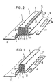
- a special embodiment of the channel profile according to the invention is already equipped with a filled expansion joint 14 by the manufacturer or in the factory (FIGS. 2 and 3).
- an L-profile 16 is arranged by the manufacturer over the joint web 8 such that the horizontal leg 17 of the L-profile 16 runs parallel to the joint leg 8 and a U- between the vertical leg 18 of the L-profile 16 and the U-leg wall 7 shaped expansion groove 19 is formed.
- the expansion joint groove 19 is prefilled with a joint-filling joint filler 20, which is round in cross-section and made of, for example, a polyethylene round profile.
- the expansion joint 14 is filled with an epoxy grout 21, which is permanently elastic and has a high adhesive strength with respect to the interior of the expansion joint, in such a way that over the joint pre-filling material 20 the L-profile 16 sticks firmly to the channel profile 1, so firmly that the channel profile 1 is easy to handle, even in rough construction.
- the embodiment of the gutter profile according to FIGS. 2 and 3 enables a laying as shown in FIG. 3.
- the channel profile is combined with the expansion joint 14 and the synthetic resin mortar compound 11 as a one-piece element with the fresh screed. Then can be tiled against the leg 18 of the L-profile 16.
- the upper edge of the leg 18 of the L-profile 16 lies flush with the surface of the floor wall 5.
- the surface of the floor tiles also lies in this plane.
- the floor tiles with the screed underneath can be supported on the leg 17 of the L-profile 16.
- the upper edge of the L-profile 15 protects the upper edge of the tile in the area of the front edge 13 of the floor tile 13a in such a way that no further damage is to be feared. Since the L-profile 16 is only connected to the channel profile 1 via the joint compound 21 and this compound is permanently elastic, the expansion joint can work properly.
- the grout 21 has been selected from a variety of possible masses. It consists of a pigmented, solvent-free, polyurethane-elasticized two-component system based on epoxy liquid resin with a formulated amine adduct hardener.
- a top coating is applied to the inner walls of the expansion joint groove 19 to increase the adhesive strength of the joint compound, which serves as an adhesion promoter.
- the coating preferably consists of a solvent-based, pigmented two-component system based on solid epoxy resin with a formulated amine-amide hardener. This product is known as anti-corrosion paint.
- this product in combination with the jointing compound provides such a high level of adhesive strength that the channel profile 1 can be stacked, shipped, laid, cut and otherwise treated with the L profile 16 without the bond being lost.
- the channel profile according to the invention ensures protection of the floor tile edge against mechanical stresses, so that considerable technical progress is achieved with the means specified.
- This construction ensures that the channels are integrated and anchored along the entire length of the screed floor. This is particularly important in areas with high thermal loads, such as these.
- B. occurs in commercial kitchens. It is precisely here that the expansion joint works properly, i.e. the independent work of the gutter and connection areas, of particular importance.
- the prefabrication of a channel element with expansion joint and connection profile enables execution under optimal workshop conditions. Compared to conventional construction site designs, there are considerable advantages, especially with hygienic requirements, since considerable thermal loads and also those caused by additional chemical cleaning agents occur here. This channel element has arisen from the need to remedy this situation, since these connection areas have so far always posed major problems which, for. B. can lead to the closure of a kitchen by the regulatory authority.
Landscapes
- Engineering & Computer Science (AREA)
- Architecture (AREA)
- Civil Engineering (AREA)
- Structural Engineering (AREA)
- Floor Finish (AREA)
- Sewage (AREA)
- Building Environments (AREA)
- Bridges Or Land Bridges (AREA)
- Investigation Of Foundation Soil And Reinforcement Of Foundation Soil By Compacting Or Drainage (AREA)
- Laying Of Electric Cables Or Lines Outside (AREA)
Abstract
Description
- Die Erfindung betrifft ein Bodenrinnenprofil für eine Bodenablaufrinne im Bereich einer Flächenentwässerung.
- Aus derartigen Bodenrinnenprofilen werden Bodenablaufrinnen in z.B. Großküchen im Koch-, Brat- und Spülbereich, in der Getränkeindustrie, in Schlachthöfen, in der chemischen Industrie, in Molkereien und in Schwimmbädern oder dgl. aufgebaut. Die Bodenablaufrinne ist mit einer Abdeckung, z.B. einem Gitterrost, abgedeckt und steht mit einem Sinkkasten in Verbindung, durch den das in der Rinne aufgefangene und transportierte flüssige Medium in bauseits vorgesehene Entsorgungsleitungen abgeleitet wird. Die Bodenablaufrinne ist oberhalb der Rohbetondecke im Estrich oder Aufbeton angeordnet. Der Fußboden neben der Rinne ist meist verfliest, wobei zwischen dem Rinnenprofil und den Fliesen eine Dehnungsfuge vorgesehen ist. Die Dehnungsfuge ist mit einem dauerelastischen Material, z.B. einem Silikonmaterial, ausgefüllt. Die Rinnenprofile bestehen meist aus Chrom-Nickel-Stahl und sind so ausgebildet und verlegt, daß sie selbsttragend und bedingt lasttragend im Rahmen üblicher Beanspruchungen sind.
- Die Bodenablaufrinnenprofile sind - im Querschnitt betrachtet - als U-förmige Wannen häufig mit beidseitigem oder allseitigem Gefälle in Richtung Sinkkasten ausgebildet. Die Rinnenseitenteile weisen zur Randstabilisierung ein Abschlußprofil in zur U-Form der Wanne umgekehrter U-Form auf. Für die Rostauflagerung sind umlaufende Auflagerungsnocken oder -ränder oder -kanten vorgesehen. Die Abdekkung erfolgt mit einem Rost, das meist ebenfalls aus Chrom-Nickel-Stahl besteht.
- Am Rinnenprofil sind Maueranker angeschweißt, die in den Estrich greifen und die Rinne fixieren.
- Ein ungelöstes, seit Jahren bekanntes Problem stellt der Übergangsbereich zwischen den Fliesen und dem Rinnenprofil dar. Selbst wenn dort eine Dehnungsfuge bauseits einwandfrei hergestellt ist, - was nicht immer der Fall ist und schon deshalb eine Fehlerquelle darstellt - wird die Dehnungsfuge mit der Zeit ausgespült, weil das weichelastische Material den Reinigungsmitteln und vor allem den Temperaturen der Reinigungsflüssigkeiten nicht standhält. Die Fliesen brechen unter Belastung an den Kanten und bilden mit den ausgespülten Dehnungsfugen Schmutzfanglöcher. Diese schadhaften Stellen müssen ausgebessert werden, was beachtliche Kosten verursacht. Die Qualität der Ausbildung des Übergangsbereichs ist abhängig vom Können des Fliesenlegers. Es kommt häufig vor, daß aus Unachtsamkeit Fehler unterlaufen und die Dehnungsfuge schadhaft ist. Die Folgen sind die gleichen, wie oben beschrieben.
- Aufgabe der Erfindung ist, mot einfachen Mitteln Problemzonen zwischen Rinnenprofil und Fliesenboden als mögliche Fehlerquelle auszuschließen.
- Diese Aufgabe wird durch die Merkmale des Hauptanspruchs gelöst. Vorteilhafte Weiterbildungen der Erfindung werden in den Unteransprüchen gekennzeichnet. Anhand der Zeichnung wird die Erfindudng im folgenden beispielhaft näher erläutert. Es zeigen:
- Fig. 1 perspektivisch einen Teil eines erfindungsgemäßen Bodenrinnenprofils,
- Fig. 2 perspektivisch einen Teil eines weiteren erfindungsgemäßen Bodenrinnenprofils,
- Fig. 3 einen Querschnitt durch den Randbereich einer Bodenablaufrinne mit dem erfindungsgemäßen Bodenrinnenprofil.
- Das Rinnenprofil 1 weist einen Boden 2 und zwei vertikale Seitenwände 3, von denen nur eine abgebildet ist, auf. In die Seitenwand 3 ist eine Auflagestufe 4 für die Abdeckung, z.B. den Gitterrost 22 (Fig. 3), eingebracht. Anstelle der Auflagestufe 4 können Kanten oder Nocken vorgeshen sein.
- Der obere Endbereich jeder Seitenwand 3 bildet eine U-Schenkelwandung 3a eines U-förmigen Abschlußprofils 6, das zudem eine horizontale Bodenwandung 5 und davon abgekantet die zweite U-Schenkelwandung 7 aufweist. Insoweit entspricht das Rinnenprofil 1 herkömmlichen Profilen.
- Nach einer Ausführungsform der Erfindung (Fig. 1) ist an die U-Schenkelwandung 7 ein nach außen rechtwinklig abgewinkelter Fugensteg 8 angebunden, in den erfindungsgemäß Durchbrüche in Form von Löchern, insbesondere Langlöchern 9, eingebracht sind. Des weiteren ist werksseitig der Innenraum 10 des Abschlußprofils 6 mit einer Kunstharzmörtelmasse 11 o. dgl. voll ausgefüllt, so daß sich eine ebene Unterfläche 12 ergibt, die bündig mit den Unterflächen der Auflagestufe 4 und des Fugenstegs 8 abschließt. Durch diese werksseitige Ausfüllung wird ein Profil auf dem Markt angeboten, das dem Fliesenleger keinerlei Probleme mehr stellt bezüglich der vollständigen Ausfüllung des Innenraums 10. Außerdem wird erreicht, daß eine hohlraumfreie Ausfüllung gewährleistet werden kann, was dem Fliesenleger, der bisher dafür verantwortlich war, nur mit außerordentlichem Aufwand gelingt. Hohlräume sind jedoch aus den oben genannten Hygienegründen zu vermeiden.
- Der Fugensteg 8 dient als Widerlager für die darüber angeordnete Fliesenreihe und Estrichunterlage, deren Belastung auf diesen Steg übertragen werden kann, was zu einer deutlichen Verbesserung der Festigkeit dieser Zonen beiträgt. Zwischen der Fliesenvorderkante 13 und der U-Schenkelwandung 7 ist bauseits die Dehnungsfuge anzuordnen, deren Boden vom Fugensteg 8 gebildet wird und die in an sich bekannter Weise hergestellt und verfüllt wird. Die Durchbrüche bzw. Langlöcher 9, deren Form und Anzahl beliebig sein können, dienen dazu, daß Estrichfrischmörtelmasse beim Verlegen des Rinnenprofils durch die Löcher dringen kann und nach dem Erhärten des Mörtels eine Art Verankerung des Rinnenprofils in der Estrichfestmörtelmasse gegen seitliches Versetzen gewährleistet ist. Zudem können an sich bekannte Ankerbolzen 15 am Fugensteg 8 angeordnet sein, die sich senkrecht nach unten in den Estrich 24 erstrecken.
- Eine besondere Ausführungsform des erfindungsgemäßen Rinnenprofils ist herstellerseitig bzw. werksseitig bereits mit einer gefüllten Dehnfuge 14 ausgerüstet (Fig. 2 und 3). Hierfür wird herstellerseitig ein L-Profil 16 über dem Fugensteg 8 derart angeordnet, daß der horizontale Schenkel 17 des L-Profils 16 parallel zum Fugenschenkel 8 verläuft und zwischen dem vertikalen Schenkel 18 des L-Profils 16 und der U-Schenkelwandung 7 eine U-förmige Dehnungsfugenrinne 19 entsteht. Über dem Boden ist die Dehnungsfugenrinne 19 mit einem im Querschnitt runden und geschlossenporigen Fugenvorfüllmaterial 20 aus z.B. Polyethylen-Rundprofil vorgefüllt. Über dem Fugenvorfüllmaterial 20 ist die Dehnungsfuge 14 mit einer Epoxidharz-Fugenmasse 21 aufgefüllt, die dauerelastisch ist und eine hohe Klebkraft bezüglich der Dehnungsfugeninnenwandung aufweist, derart, daß das L-Profil 16 fest am Rinnenprofil 1 klebt, und zwar so fest, daß das Rinnenprofil 1 ohne weiteres handhabbar ist, selbst im rauhen Baubetrieb.
- Vorteilhaft ist, wenn im Schenkel 17 des L-Profils 16 Durchbrüche, vorzugsweise Löcher, in Form von Langlöchern 9a, eingebracht sind, deren Aufgabe und Funktion den Langlöchern 9 entspricht. Des weitern ist vorteilhaft, wenn am Schenkel 17 des L-Profils 16 nach unten in den Estrich 24 ragende Ankerbolzen 23 angeordnet sind.
- Die Ausführungsform des Bodenrinnenprofils gemäß den Fig. 2 und 3 ermöglicht eine Verlegung, wie sie in Fig. 3 dargestellt ist. Das Rinnenprofil wird mit der Dehnungsfuge 14 und der Kunstharzmörtelmasse 11 als einstückiges Element mit dem frischen Estrich kombiniert. Anschließend kann gegen den Schenkel 18 des L-Profils 16 verfliest werden. Die Oberkante des Schenkels 18 des L-Profils 16 liegt fluchtend in einer Ebene mit der Oberfläche der Bodenwandung 5. In dieser Ebene liegt auch die Oberfläche der Bodenfliesen. Die Bodenfliesen mit dem darunter befindlichen Estrich können sich auf dem Schenkel 17 des L-Profils 16 abstützen. Die Oberkante des L-Profils 15 schützt die Fliesenoberkante im Bereich der Vorderkante 13 der Bodenfliese 13a derart, daß keine Beschädigungen mehr zu befürchten sind. Da das L-Profil 16 lediglich über die Fugenmasse 21 mit dem Rinnenprofil 1 verbunden ist und diese Masse dauerelastisch ist, kann die Dehnungsfuge einwandfrei arbeiten.
- Die Fugenmasse 21 ist aus einer Vielzahl von möglichen Massen ausgewählt worden. Sie besteht aus einem pigmentierten lösungsmittelfreien, mit Polyurethan elastifiziertem Zweikomponentensystem auf Epoxid-Flüssigharz-Basis mit formuliertem Amin-Addukt-Härter.
- Nach einer besonderen Ausführungsform der Erfindung wird zur Erhöhung der Klebkraft der Fugenmasse eine Deckbeschichtung auf die Innenwandungen der Dehnungsfugenrinne 19 aufgebracht, die als Haftvermittler dient. Die Beschichtung besteht vorzugsweise aus einem lösungsmittelhaltigen, pigmentierten Zweikomponenten-System auf Epoxid-Festharzbasis mit formuliertem Amin-Amid-Härter. Dieses Produkt ist als Korrosionsschutzanstrich bekannt.
- Es ist überraschend, daß dieses Produkt in Kombination mit der Fugenmasse eine so hohe Klebkraft zur Verfügung stellt, daß das Rinnenprofil 1 mit dem L-Profil 16 gestapelt, versendet, verlegt, geschnitten und anderweitig behandelt werden kann, ohne daß der Verbund verlorengeht.
- Mit der Erfindung ist es somit gelungen, die Verlegung des Rinnenprofils derart zu erleichtern, daß keine besondere Sorgfalt aufgewendet werden muß, um eine ordnungsgemäße Dehnfuge zur Verfügung zu stellen. Außerdem gewährleistet das erfindungsgemäße Rinnenprofil einen Schutz der Bodenfliesenkante gegen mechanische Beanspruchungen, so daß mit den angegebenen Mitteln ein erheblicher technischer Fortschritt erzielt wird.
- Durch diese Konstruktion wird erreicht, daß die Rinnen auf der gesamten Länge in den Estrichboden eingebunden und verankert sind. Dies ist besonders wichtig in Bereichen mit hoher thermischer Belastung, wie diese z. B. in Großküchen auftritt. Gerade hier ist deshalb die einwandfreie Funktionsweise der Dehnungsfuge, d.h. das unabhängige Arbeiten der Rinne und Anschlußbereiche, von besonderer Bedeutung. Die Vorfertigung eines Rinnenelementes mit Dehnungsfuge und Anschlußprofil ermöglicht eine Ausführung unter optimalen Werkstattbedingungen. Gegenüber bisher üblichen Baustellenausführungen ergeben sich erhebliche Vorteile, besonders auch bei hygienischen Anforderungen, da hier erhebliche thermische Belastungen und auch solche durch zusätzliche chemische Reinigungsmittel auftreten. Dieses Rinnenelement ist entstanden aus der Notwendigkeit, hier Abhilfe zu schaffen, da diese Anschlußbereiche bisher noch überall große Probleme aufwerfen, die z. B. bis zur Schließung einer Küche durch die Aufsichtsbehörde führen können.
Claims (11)
Priority Applications (1)
| Application Number | Priority Date | Filing Date | Title |
|---|---|---|---|
| AT88104314T ATE61076T1 (de) | 1987-04-17 | 1988-03-18 | Bodenrinnenprofil fuer eine bodenablaufrinne. |
Applications Claiming Priority (2)
| Application Number | Priority Date | Filing Date | Title |
|---|---|---|---|
| DE19873713173 DE3713173A1 (de) | 1987-04-17 | 1987-04-17 | Bodenrinnenprofil fuer eine bodenablaufrinne |
| DE3713173 | 1987-04-17 |
Publications (3)
| Publication Number | Publication Date |
|---|---|
| EP0286863A2 true EP0286863A2 (de) | 1988-10-19 |
| EP0286863A3 EP0286863A3 (en) | 1989-04-26 |
| EP0286863B1 EP0286863B1 (de) | 1991-02-27 |
Family
ID=6325891
Family Applications (1)
| Application Number | Title | Priority Date | Filing Date |
|---|---|---|---|
| EP88104314A Expired - Lifetime EP0286863B1 (de) | 1987-04-17 | 1988-03-18 | Bodenrinnenprofil für eine Bodenablaufrinne |
Country Status (3)
| Country | Link |
|---|---|
| EP (1) | EP0286863B1 (de) |
| AT (1) | ATE61076T1 (de) |
| DE (2) | DE3713173A1 (de) |
Families Citing this family (2)
| Publication number | Priority date | Publication date | Assignee | Title |
|---|---|---|---|---|
| DE4115638A1 (de) * | 1991-05-14 | 1992-11-19 | Fritz Manderbach Kg | Boden-entwaesserungsrinne |
| DE9111962U1 (de) * | 1991-09-25 | 1991-11-28 | Hauraton Betonwarenfabrik GmbH & Co KG, 7550 Rastatt | Rinnenbauteil |
Family Cites Families (10)
| Publication number | Priority date | Publication date | Assignee | Title |
|---|---|---|---|---|
| FR439132A (fr) * | 1911-03-28 | 1912-06-06 | Celestin Montcocol | Dispositif de fixation de dalles réversibles |
| GB1012211A (en) * | 1962-03-05 | 1965-12-08 | Jungbluth Otto | Improvements in or relating to a sheet structure for forming a roof or floor structure |
| US3827204A (en) * | 1972-03-14 | 1974-08-06 | Thiokol Chemical Corp | Sealed joint for sectionalized flooring and method of making the same |
| DE2413340A1 (de) * | 1974-03-20 | 1975-10-30 | Juergen Jora | Verfahren zum auskleiden von zwischen koerperwandungen liegenden fugen |
| AT327819B (de) * | 1974-11-19 | 1976-02-25 | Guggemos Horst | Sohlschale fur gerinne, insbesondere fur kanale |
| DE2538909B2 (de) * | 1975-09-02 | 1978-04-06 | Dyckerhoff & Widmann Ag, 8000 Muenchen | Dichtungsmittel zum Abdichten von Bauwerksfugen |
| GB2076868B (en) * | 1980-05-09 | 1983-12-07 | Yugen Kaisha Shinnihon Seisaku | Frame member |
| DE3309178A1 (de) * | 1982-03-16 | 1983-09-29 | Wilhelm Hafner GmbH, 7752 Reichenau | Rinne insbesondere zum verlegen im fussboden eines massraumes |
| DE8506750U1 (de) * | 1985-03-08 | 1985-07-04 | Wedi, Stephan, 4407 Emsdetten | Bewegungsfugenleiste für Fußbodenkonstruktionen |
| JP2808794B2 (ja) * | 1990-02-22 | 1998-10-08 | ソニー株式会社 | 両面光ディスク |
-
1987
- 1987-04-17 DE DE19873713173 patent/DE3713173A1/de active Granted
-
1988
- 1988-03-18 DE DE8888104314T patent/DE3861811D1/de not_active Expired - Lifetime
- 1988-03-18 EP EP88104314A patent/EP0286863B1/de not_active Expired - Lifetime
- 1988-03-18 AT AT88104314T patent/ATE61076T1/de active
Also Published As
| Publication number | Publication date |
|---|---|
| DE3861811D1 (de) | 1991-04-04 |
| EP0286863A3 (en) | 1989-04-26 |
| DE3713173A1 (de) | 1988-11-03 |
| DE3713173C2 (de) | 1989-02-02 |
| ATE61076T1 (de) | 1991-03-15 |
| EP0286863B1 (de) | 1991-02-27 |
Similar Documents
| Publication | Publication Date | Title |
|---|---|---|
| DE4206005C3 (de) | Balkon | |
| DE1484307A1 (de) | Deckenelement fuer Fertigbauten | |
| EP1181883B1 (de) | Untergestell für eine Duschwanne | |
| DE202004004965U1 (de) | Schalungselement | |
| DE2005319A1 (de) | Eckeneinsatz | |
| EP0286863B1 (de) | Bodenrinnenprofil für eine Bodenablaufrinne | |
| DE4230682C2 (de) | Rinnenanordnung für den Schwerverkehrbereich | |
| DE8705702U1 (de) | Bodenrinnenprofil für eine Bodenablaufrinne | |
| EP2716839A1 (de) | Schalungselement | |
| DE9219027U1 (de) | Trägerprofil für eine tragende Konstruktion eines Balkons | |
| EP3546666A1 (de) | Holz-beton-verbindungsbausatz | |
| DE102019106018A1 (de) | Holz-Beton-Verbindungsbausatz | |
| EP1911882A2 (de) | System zur Herstellung eines Belags für begeh- und/oder befahrbare Dachflächen, Erdreichabdeckungen oder dergleichen | |
| DE1961171A1 (de) | Halterung fuer Gebaeudeaussenwandverkleidungen | |
| DE3235707A1 (de) | Bausatz fuer balken- oder rippendecken | |
| DE7318128U (de) | Kellerfenster Lichtschacht | |
| EP0534312A1 (de) | Rinnenbauteil | |
| DE8202671U1 (de) | Vorrichtung fuer den einbau einer sanitaeren einrichtung | |
| EP4446515A1 (de) | Verfahren zur anordnung einer platte an einer u-förmigen schiene | |
| DE9101799U1 (de) | Horizontales Anschlußsystem für Trennwände | |
| DE2058113A1 (de) | Bautafel und Verbindung derselben mit einer anderen Bautafel bzw. mit einer festen Wand | |
| EP0487763A1 (de) | Horizontales Anschlusssystem für Trennwände | |
| DE3308473A1 (de) | Bausatz fuer balken- oder rippendecken | |
| DE69901101T2 (de) | Deckel für eine schachtabdeckung | |
| DE8014149U1 (de) | Bewegungsfugen-Dichtungsprofil |
Legal Events
| Date | Code | Title | Description |
|---|---|---|---|
| PUAI | Public reference made under article 153(3) epc to a published international application that has entered the european phase |
Free format text: ORIGINAL CODE: 0009012 |
|
| AK | Designated contracting states |
Kind code of ref document: A2 Designated state(s): AT CH DE FR GB LI NL |
|
| PUAL | Search report despatched |
Free format text: ORIGINAL CODE: 0009013 |
|
| AK | Designated contracting states |
Kind code of ref document: A3 Designated state(s): AT CH DE FR GB LI NL |
|
| 17P | Request for examination filed |
Effective date: 19890406 |
|
| 17Q | First examination report despatched |
Effective date: 19900510 |
|
| GRAA | (expected) grant |
Free format text: ORIGINAL CODE: 0009210 |
|
| RAP1 | Party data changed (applicant data changed or rights of an application transferred) |
Owner name: BASIKA ENTWAESSERUNGEN GMBH |
|
| AK | Designated contracting states |
Kind code of ref document: B1 Designated state(s): AT CH DE FR GB LI NL |
|
| REF | Corresponds to: |
Ref document number: 61076 Country of ref document: AT Date of ref document: 19910315 Kind code of ref document: T |
|
| PG25 | Lapsed in a contracting state [announced via postgrant information from national office to epo] |
Ref country code: DE Effective date: 19910309 |
|
| PG25 | Lapsed in a contracting state [announced via postgrant information from national office to epo] |
Ref country code: AT Effective date: 19910318 |
|
| GBT | Gb: translation of ep patent filed (gb section 77(6)(a)/1977) | ||
| PG25 | Lapsed in a contracting state [announced via postgrant information from national office to epo] |
Ref country code: LI Free format text: LAPSE BECAUSE OF NON-PAYMENT OF DUE FEES Effective date: 19910331 Ref country code: CH Free format text: LAPSE BECAUSE OF NON-PAYMENT OF DUE FEES Effective date: 19910331 |
|
| REF | Corresponds to: |
Ref document number: 3861811 Country of ref document: DE Date of ref document: 19910404 |
|
| ET | Fr: translation filed | ||
| PG25 | Lapsed in a contracting state [announced via postgrant information from national office to epo] |
Ref country code: NL Effective date: 19911001 |
|
| NLV4 | Nl: lapsed or anulled due to non-payment of the annual fee | ||
| REG | Reference to a national code |
Ref country code: CH Ref legal event code: PL |
|
| PLBI | Opposition filed |
Free format text: ORIGINAL CODE: 0009260 |
|
| 26 | Opposition filed |
Opponent name: PASSAVANT-WERKE AG & CO. KG Effective date: 19911126 |
|
| PG25 | Lapsed in a contracting state [announced via postgrant information from national office to epo] |
Ref country code: FR Effective date: 19920131 |
|
| REG | Reference to a national code |
Ref country code: FR Ref legal event code: ST |
|
| RDAG | Patent revoked |
Free format text: ORIGINAL CODE: 0009271 |
|
| STAA | Information on the status of an ep patent application or granted ep patent |
Free format text: STATUS: PATENT REVOKED |
|
| 27W | Patent revoked |
Effective date: 19920421 |
|
| GBPR | Gb: patent revoked under art. 102 of the ep convention designating the uk as contracting state | ||
| PG25 | Lapsed in a contracting state [announced via postgrant information from national office to epo] |
Ref country code: FR Effective date: 19910331 |