EP0286881A2 - Impulsgenerator mit abgeschirmtem Wieganddraht - Google Patents
Impulsgenerator mit abgeschirmtem Wieganddraht Download PDFInfo
- Publication number
- EP0286881A2 EP0286881A2 EP88104692A EP88104692A EP0286881A2 EP 0286881 A2 EP0286881 A2 EP 0286881A2 EP 88104692 A EP88104692 A EP 88104692A EP 88104692 A EP88104692 A EP 88104692A EP 0286881 A2 EP0286881 A2 EP 0286881A2
- Authority
- EP
- European Patent Office
- Prior art keywords
- magnet
- wiegand wire
- module
- wire
- magnetic
- Prior art date
- Legal status (The legal status is an assumption and is not a legal conclusion. Google has not performed a legal analysis and makes no representation as to the accuracy of the status listed.)
- Granted
Links
Images




Classifications
-
- H—ELECTRICITY
- H03—ELECTRONIC CIRCUITRY
- H03K—PULSE TECHNIQUE
- H03K17/00—Electronic switching or gating, i.e. not by contact-making and –breaking
- H03K17/94—Electronic switching or gating, i.e. not by contact-making and –breaking characterised by the way in which the control signals are generated
- H03K17/965—Switches controlled by moving an element forming part of the switch
- H03K17/97—Switches controlled by moving an element forming part of the switch using a magnetic movable element
-
- H—ELECTRICITY
- H03—ELECTRONIC CIRCUITRY
- H03K—PULSE TECHNIQUE
- H03K3/00—Circuits for generating electric pulses; Monostable, bistable or multistable circuits
- H03K3/02—Generators characterised by the type of circuit or by the means used for producing pulses
- H03K3/45—Generators characterised by the type of circuit or by the means used for producing pulses by the use, as active elements, of non-linear magnetic or dielectric devices
Definitions
- This invention relates in general to a pulser for generating a pulse by switching the state of a magnetic device that has come to be known as a Wiegand wire and, more particularly, to a mechanism and method for controlling the magnetic field to which a Wiegand wire module is subjected so as to provide an improved output pulse.
- the magnetic device employing the pulser of this invention is of the type disclosed in U.S. Patent No. 4,247,601 issued January 27, 1981.
- This magnetic device is a ferro-magnetic wire segment which has been treated to provide core and shell portions with divergent magnetic properties.
- the wire is now known in the art as a Wiegand wire.
- the Wiegand wire essentially has two states. In one of these states, the magnetization of the core and shell are in opposite directions and this state may conveniently be called a reverse state. In the other state, the magnetization of the core and shell are in the same direction and this state may conveniently be called the confluent state.
- the wire switches state. The switch in state is extremely rapid so that the rate of change of flux through a pick-up coil wrapped around the wire is great. As a consequence the output from the pick-up coil is very substantial, in some cases being as high as eight volts into an open circuit on a repeatable basis.
- the wire and pick-up coil is referred to as a module.
- the characteristics of a pulse generator which are desirable include simplicity, low cost, versatility, repeatability, reliability and high output pulse. There are inevitably certain trade-offs in enhancing certain of these characteristics at the expense of other characteristics. However, it is desirable to provide an optimum combination of these characteristics with whatever enhancement of the characteristics may be achieved in an improved design and such is the general purpose of this invention.
- U.S. Patent No. 4,309,628 issued January 5, 1982 discloses an arrangement in which a Wiegand wire module is triggered by a shunt element.
- various shunt structures which might be employed to provide a shunt trigger for the Wiegand wire.
- Disclosed in that patent are (1) a non-ferrous disk with low reluctance elements deployed on the face of the disk, (2) a rotating non-ferrous drum with low-reluctance elements deployed around the rim of the drum, (3) a ferrous rotating disk with a series of ferrous lobes that protrude radially from the rim of the disk, and (4) a ferrous rotating disk with a plurality of cut-out zones on the face of the disk.
- U.S. Patent No. 4,484,090 entitled Pulsed Generator With Shaped Magnetic Field issued November 20, 1984 discusses the problem that arises because of the demagnetization field at the ends of the Wiegand wire. That patent discloses a pulser in which the excitation field is shaped so as to minimize the axial field at the ends of the wire thereby minimizing the effects of the demagnetization field at the end of the wire.
- This shaped field design provides an improved pulser in that the more rapid switch in flux when the demagnetization field is minimized provides a larger output pulse in the pick-up coil than is the case when the field at the ends of the wire is significant.
- the increased pulse magnitude provided by the shaped field design disclosed in this patent serves to enhance the utility of the pulser.
- the improvement provided is not as consistent and repeatable as is desirable in operating equipment. In particular, the effects of ambient fields and, most particularly, changing ambient fields results in a loss of repeatability and consistent pulse output magnitude.
- the pulse generating unit of this invention involves a Wiegand wire module mounted within two soft ferro-magnetic guide elements. These two guide elements perform two major functions.
- the first function is to magnetically shield the two ends of the Wiegand wire module so as to substantially eliminate the known end demagnetization effect which reduces the output pulse when the Wiegand wire switches state. This is achieved by having small cylindrical cavity elements within each of the two shunts into which cavity elements the ends of the Wiegand wire module are mounted.
- the second major function is to collect, conduct and guide incident flux from an adjacent drive magnet in such a fashion as to direct the flux across an air gap between the two shunt elements. The result is to assure that there will be enough leakage flux to drive the Wiegand wire and thus cause it to change state.
- the change of state of the Wiegand wire provides a rapid change in the flux coupled through the pick-up coil on the module thereby producing a significant and usable output pulse.
- this pulser unit when combined with a movable magnet that upon motion is coupled and uncoupled to the Wiegand wire, provides a device that can be used as a proximity measuring device, a speed measuring device or a position measuring device.
- magnets mounted onto the guide elements constitute flux generating units for first and second magnetic circuits, respectively.
- the polarity of the magnets and their positioning is such that the flux from the two magnetic circuits are substantially equal in amplitude and opposite in direction at an air gap between the two guide elements. The result is that in the normal state, the Wiegand wire is subject to substantially no incident flux.
- a low reluctance shunt brought adjacent to the magnets in the first magnetic circuit substantially reduces the reluctance in that circuit thereby increasing the flux in that circuit.
- the result is an unbalance of flux at an air gap between the two guide elements.
- the unbalanced leakage flux is enough to drive the Wiegand wire and cause it to change state.
- the change in state of the Wiegand wire provides rapid change in the flux coupled through the pick-up coil on the module thereby producing a significant usable output pulse.
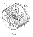
- the pulser 10 includes a Wiegand wire module 11 mounted within a cavity that is defined by two magnetically soft ferro-magnetic guide elements 12.
- the module 11 and both guides 12 are held on a molded plastic base 14.
- Two terminals 16 extend through the base 14 and are connected to the ends of the pick-up coil 18 that is a part of the module 11.
- a stainless steel cap 20 fits over the guide elements 12 and the periphery of the base 14.
- the base 14 includes a short positioning lug 17 to aid in orienting the pulser when assembling it onto other equipment.
- the module 11 consists of (a) a Wiegand wire element 22 held within a glass tube 24 and (b) the pick-up coil 18 wound around the central portion of the glass tube 24.
- the coil 18 is coupled to the changing magnetic field produced by the switch in the magnetic state of the Wiegand wire 22.
- the ends of the glass tube 24, and thus the ends of the Wiegand wire 22, are mounted in shallow cylindrical recesses 12a of the guide elements 12.
- Rubber end caps 26 are positioned over the ends of glass tube 24 and fit within the cylindrical recesses 12a so as to provide a firm, resilient and safe mount for the glass tube 24. These end caps 26 extend inboard along the conical walls of the cavity in the guide 12. Only one end cap 26 is shown. The break away view eliminates the other cap.
- each guide element 12 The cavity within each guide element 12 is defined by the cylindrical recess 12a at the outboard ends of each cavity and by the truncated conical zone 12b which is inboard from the cylindrical recess 12a.
- the conical cavity zone 12b has its smallest diameter at the cylindrical recess 12a and increases in diameter to the central face 12f of the guide element 12.
- the central faces 12f of the two guide elements 12 are spaced from one another thereby establishing a small gap 28 between the two guide elements 12.
- Lead wires 18a from the pick-up coil 18 are wrapped around a folded over terminal end 16a which is crimped and welded to hold the lead wires 18a in place and assure good electrical contact.
- the terminal 16 is a cylindrical terminal that extends through the plastic base 14 and has the flat end 16a. Accordingly, an output pulse generated in the pick-up coil 18 will be transmitted to the terminal 16.
- the pulser 10 may be magnetically driven by a set of magnets 32 mounted on the periphery of a rotatable disc 30.
- the disc 30 and pulser 10 provide a set of output pulses which measure the rotational speed of the device.
- each magnet 32 passes over the top of the cap 20, it is magnetically coupled to the Wiegand wire 22 thereby causing the Wiegand wire 22 to switch state. This state switch generates an output pulse in the pick-up coil 18.
- the magnets 32 pass over the top of the FIG. 1 pulser unit 10 with the axis of each magnet 32 in alignment with the axis of the Wiegand wire 22.
- the wire 22 switches state and a substantial output pulse is provided (see FIG. 4A).
- the position and configuration of the guide elements 12 shape and control the magnetic field to which the Wiegand wire 22 is subjected in a fashion which optimizes the operation of the Wiegand wire segment 22.
- the conical or funnel shaped cavity area 12b conducts the flux from the exciting magnet 32 axially toward the air gap 28 between the elements 12.
- the ends of the wire 22 are substantially shielded from the external flux.
- the guide elements 12 are a soft ferro-magnetic material. In one embodiment, they are a powdered iron of magnetic grade and provide a low reluctance path for the magnetic field generated by the magnet 32.
- the cap 20, being of stainless steel material, is transparent to the magnetic flux and thus has no effect on the magnetic operation of this pulse generator unit 10.
- the pulser unit 10 of FIG. 1 may be actuated by a rotating disk 30, as shown in FIG. 4.
- the disk 30 has a series of magnets 32 of alternating polarity, as shown.
- a first one of the magnets 32 will magnetize the Wiegand wire 22 in a first direction and in doing so will provide a first output pulse.
- a second magnet 32 having opposite polarity will drive the Wiegand wire into an opposing magnetic polarity and will generate a second pulse.
- the pulses generated by alternate magnets in the FIG. 4 embodiment will be of opposite polarity.
- a waveform of the output pulse train from the FIG. 4 arrangement is shown in FIG. 4A.
- FIG. 1 design What has been observed about the FIG. 1 design is that it is very forgiving of alignment and spacing variations between the actuating magnet 32 and the pulser unit 10.
- the pulser 10 will operate to provide the output pulse.
- the spacing between the magnet 32 and the pulser unit 10 varies, the desired output pulse will be obtained.
- the guide elements 12 serve to collect, conduct, and guide the incident flux from the magnet 32 in such as fashion as to concentrate this flux across the gap 28 in a direction that is parallel to the axis of the Wiegand wire 22. This concentration of flux saturates the air gap between the elements 12 thereby creating enough leakage flux to subject the Wiegand wire 22 to an optimal excitation field.
- the guide elements 12 provide both a magnetic shielding function for the ends of the Wiegand wire and a magnetic flux ducting function to facilitate switching.
- a glass tube 24 approximately 1.1 cm long contains a Wiegand wire segment 22 that is approximately 1 cm in length.
- Wire 22 has a diameter of approximately one-quarter millimeter and it is slipped into the tube 24 which has an outer diameter of approximately 1 mm and an inner diameter of approximately 0.38 mm.
- the wire need not be fastened inside the tube because the two end-caps 26 prevent the wire from falling out.
- the coil 18 has 2,000 turns of No. 44 magnet wire and it is positioned on the center 7 mm of the tube 24. Approximately 2 mm of each end of the tube 24 is contained in the cap portion of the rubber end-cap 26.
- Each element 12 is made out of magnetic grade powdered iron and has an overall length of approximately 6.3 mm and square sides of approximately 6.3 mm.
- the axial length of the two cavities 12a and 12b is approximately 5 mm and the axial length of the cavity 12b is approximately 2.8 mm.
- the gap 28 between the two faces 12f is approximately 2.54 mm.
- the drive field may be created by a solenoid with the Wiegand wire positioned in the center of the solenoid and the ends of the wire well within the solenoid. That long solenoid drive field is analogous to the excitation of the Wiegand wire by a magnet passing the wire where the field of the magnet affects the ends of the wire.
- the two elements 12 provide a short field in that only the center of the wire 22 is subject to the drive field.
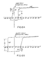
- FIGS. 5A, 5B, 6A and 6B contrast the hysteresis curves obtained by exciting the Wiegand wire in a long field and in a short field, in symmetric drive and in asymmetric drive.
- the drive refers to the field imposed on the Wiegand wire by an external source such as a solenoid or a magnet.
- the long drive field arrangement which has been extensively employed, provides a switching model that does not adequately explain the results of the short drive field.
- the switching state of the Wiegand wire produces a change in the field around the wire which can be sensed by a pick-up coil to provide an output pulse. Because this change of state occurs rapidly, the rate of change of flux with time is significant enough to provide a meaningful output pulse.
- FIG. 6A illustrates what happens under asymmetric drive employing the long drive field.
- a strong positive drive field forces core and shell into the same magnetization.
- the asymmetric drive results in asymmetric pulses.
- the strong excitation field at the zone 55 of FIG. 6A, has created a confluent state for the wire, the decrease in the magnitude of the excitation field to a small negative value, as the zone 56, produces the relatively small output pulse similar to that shown in FIG. 5A when the wire switches from its confluent state to its reverse state.
- one of the advantages of this invention involving an effective, repeatable short field drive is that it makes possible the symmetric drive arrangement with the two substantial pulses per cycle, at zones 58 and 59 as shown in FIG. 5B. It is believed that the underlying reason for the substantial pulse developed at 57 in FIG. 6A is the same as the reason for the substantial pulses developed at 58 and 59 in FIG. 5B. However, it is not clear why these substantial pulses are created under these conditions. It is notable that the short field asymmetric drive provides a hysteresis curve as shown at FIG. 6B in which the substantial output pulse occurs at the zone 60. It is not known why the single substantial pulse per cycle provided by asymmetric drive should appear at different places in the long field and short field hysteresis loops.
- FIGS. 1 and 7 are similar to the FIG. 1 embodiment except that magnets M1, M2, M3 and M4 are mounted on the guide elements 12a and 12b. Accordingly, the same reference numerals are used in FIGS. 1 and 7 to indicate identical parts.
- a first set of magnets M1, M2 are mounted respectively on first and second guide elements 12. The direction of magnetization of these magnets M1 and M2 are opposite to one another.
- the magnets M1 and M2 constitute the active elements in a first magnetic circuit which is coupled through the two guide elements 12 to the Wiegand wire module 11.
- a second set of magnets M3 and M4 are mounted respectively on first and second guide elements 12. These magnets M3 and M4 provide the active elements in a second magnetic circuit which is coupled through the two guide elements 12 to the Wiegand wire module 11.
- the magnetization of M3 and M4 are opposite in direction so that they can provide the appropriate circuit.
- the direction of magnetization of the magnets M1 and M3 on the first guide element 12 are in opposite directions from one another and of necessity the same opposite magnetization relationship exists between the magnets M2 and M4 on the second guide element 12.
- the directions of the first and second magnetic fields at the Wiegand wire module 11 are opposed to one another. Because the magnets M1, M2, M3 and M4 are of the same strength and the pairs are positioned symmetrically relative to the axis of the module 11, the strength of the two fields at the Wiegand wire module are normally equal to one another. Because they are opposite to one another, they substantially cancel out at the Wiegand wire module. Until the strength of one or the other field is substantially increased by means of shunt 40, discussed hereinafter, the Wiegand wire module 11 is substantially uninfluenced by these fields.
- the pulser is actuated by the position of a ferro-magnetic shunt element 40.
- the shunt element 40 has a removed position in which case the pulser has what might be called the open circuit state shown in FIG. 9.
- the first magnetic circuit which incorporates the magnets M1 and M2 includes the external air gap RS1 and the pole gap 28. Because of the polarity of the four magnets relative to one another, the flux generated by the first and second magnetic circuits is substantially equal in magnitude and opposite in direction across the pole gap 28. Accordingly, the net leakage flux coupled to the Wiegand wire element 22 is nil.
- the pulses generated by the alternate positions of the shunt 40 shown in FIGS. 10 and 11 will be of opposite polarity.
- a waveform of the output pulse train is the same as is shown in FIG. 4.
- a shunt element is alternatively brought adjacent to the magnets M1/M2 of the first circuit and the magnets M3/M4 of the second circuit to cause a switch of state that provides the pulse train of FIG. 4.
- the shunt that triggers these pulses need not be a single shunt element.
- a typically shunt trigger could be a rotating disk having a series of lobes or projections of low reluctance material in which each projection first triggers a positive pulse and then a negative pulse.
- the switching mode is one that has been called short field symmetric drive mode and is described in connection with FIG. 5B.
Landscapes
- Physics & Mathematics (AREA)
- Nonlinear Science (AREA)
- Measuring Magnetic Variables (AREA)
Priority Applications (1)
| Application Number | Priority Date | Filing Date | Title |
|---|---|---|---|
| AT88104692T ATE99849T1 (de) | 1987-04-14 | 1988-03-24 | Impulsgenerator mit abgeschirmtem wieganddraht. |
Applications Claiming Priority (4)
| Application Number | Priority Date | Filing Date | Title |
|---|---|---|---|
| US38010 | 1987-04-14 | ||
| US07/038,010 US4743780A (en) | 1987-04-14 | 1987-04-14 | Pulse generator with shielded Wiegand wire |
| US07/072,916 US4758742A (en) | 1987-04-14 | 1987-07-14 | Shunt activated pulse generator |
| US72916 | 1987-07-14 |
Publications (3)
| Publication Number | Publication Date |
|---|---|
| EP0286881A2 true EP0286881A2 (de) | 1988-10-19 |
| EP0286881A3 EP0286881A3 (en) | 1990-06-20 |
| EP0286881B1 EP0286881B1 (de) | 1994-01-05 |
Family
ID=26714709
Family Applications (1)
| Application Number | Title | Priority Date | Filing Date |
|---|---|---|---|
| EP88104692A Expired - Lifetime EP0286881B1 (de) | 1987-04-14 | 1988-03-24 | Impulsgenerator mit abgeschirmtem Wieganddraht |
Country Status (4)
| Country | Link |
|---|---|
| US (1) | US4758742A (de) |
| EP (1) | EP0286881B1 (de) |
| JP (1) | JP2598453B2 (de) |
| DE (1) | DE3886801D1 (de) |
Cited By (3)
| Publication number | Priority date | Publication date | Assignee | Title |
|---|---|---|---|---|
| RU2263392C2 (ru) * | 2003-04-10 | 2005-10-27 | Институт сильноточной электроники СО РАН | Генератор импульсов высокого напряжения |
| WO2017174099A1 (de) * | 2016-04-08 | 2017-10-12 | Thomas Theil | Wieganddraht-anordnung, sowie verfahren zur herstellung derselben |
| EP4481332A4 (de) * | 2022-02-16 | 2026-04-15 | Oriental Motor Co Ltd | Elektrizitätserzeugungssensor |
Families Citing this family (17)
| Publication number | Priority date | Publication date | Assignee | Title |
|---|---|---|---|---|
| US5908103A (en) * | 1997-12-05 | 1999-06-01 | Hid Corporation | Token with Wiegand wire |
| US5898241A (en) * | 1997-12-05 | 1999-04-27 | Hid Corporation | Read head for Wiegand token |
| US6744153B2 (en) * | 1998-09-18 | 2004-06-01 | Hirose Electric Co., Ltd. | Apparatus for and method of generating a pulse signal |
| US6191687B1 (en) | 1998-09-24 | 2001-02-20 | Hid Corporation | Wiegand effect energy generator |
| US6229300B1 (en) | 1998-12-03 | 2001-05-08 | Hid Corporation | Wiegand tilt sensor |
| RU2181925C2 (ru) * | 2000-02-09 | 2002-04-27 | Институт сильноточной электроники СО РАН | Генератор высоковольтных импульсов |
| RU2189695C1 (ru) * | 2001-01-09 | 2002-09-20 | Институт сильноточной электроники СО РАН | Магнитный генератор импульсов |
| US6886414B2 (en) * | 2003-04-21 | 2005-05-03 | Dresser, Inc. | Power generating meter |
| US6917858B2 (en) * | 2003-08-29 | 2005-07-12 | Dresser, Inc. | Fluid regulation |
| JP2007225536A (ja) * | 2006-02-27 | 2007-09-06 | Nikkoshi Co Ltd | 回転運動検出装置 |
| US7349813B2 (en) | 2006-05-16 | 2008-03-25 | Dresser, Inc. | Fault tolerant power system architecture for fluid flow measurement systems |
| US20090035121A1 (en) * | 2007-07-31 | 2009-02-05 | Dresser, Inc. | Fluid Flow Modulation and Measurement |
| US10103139B2 (en) * | 2015-07-07 | 2018-10-16 | Xilinx, Inc. | Method and design of low sheet resistance MEOL resistors |
| JP7641871B2 (ja) * | 2021-09-30 | 2025-03-07 | オリエンタルモーター株式会社 | 回転検出器 |
| JP7645136B2 (ja) * | 2021-06-08 | 2025-03-13 | オリエンタルモーター株式会社 | 運動検出器 |
| JP2024107939A (ja) * | 2023-01-30 | 2024-08-09 | 富士電機株式会社 | エンコーダシステム |
| JP2024153493A (ja) | 2023-04-17 | 2024-10-29 | オリエンタルモーター株式会社 | 発電センサ |
Family Cites Families (20)
| Publication number | Priority date | Publication date | Assignee | Title |
|---|---|---|---|---|
| US3105965A (en) * | 1960-04-11 | 1963-10-01 | Honeywell Regulator Co | Combined read-write and erase head assembly |
| US3820090A (en) * | 1970-01-26 | 1974-06-25 | Vlinsky M | Bistable magnetic device |
| US3818465A (en) * | 1970-07-06 | 1974-06-18 | Velsinsky M | Traveling magnetic domain wall device |
| US3866193A (en) * | 1970-07-06 | 1975-02-11 | Velinsky Milton | Asymetric bistable magnetic device |
| US3780313A (en) * | 1972-06-23 | 1973-12-18 | Velinsky M | Pulse generator |
| US3971958A (en) * | 1973-08-13 | 1976-07-27 | Alfa Romeo S.P.A. | Pulse generator for providing information as to the rate of rotation and phasing of an engine to an electronic apparatus intended to govern the fuel feed to an internal combustion engine of the fuel injection type |
| US3879754A (en) * | 1973-11-29 | 1975-04-22 | Honeywell Inc | Magnetic field producing apparatus |
| US4164770A (en) * | 1977-09-21 | 1979-08-14 | Eastman Technology, Inc. | Thin film magnetoresistive head |
| US4136370A (en) * | 1977-09-21 | 1979-01-23 | Eastman Technology, Inc. | Magnetic film sensor |
| US4123790A (en) * | 1977-09-21 | 1978-10-31 | Eastman Technology, Inc. | Magnetic head with mechanically isolated thin film sensor |
| US4263523A (en) * | 1978-04-18 | 1981-04-21 | The Echlin Manufacturing Company | Pulse generator using read head with Wiegand wire |
| US4247601A (en) * | 1978-04-18 | 1981-01-27 | The Echlin Manufacturing Company | Switchable magnetic device |
| DE2817169C2 (de) * | 1978-04-20 | 1986-10-23 | Robert Bosch Gmbh, 7000 Stuttgart | Einrichtung zur Abgabe von Impulsen |
| DE2826609C2 (de) * | 1978-06-19 | 1986-12-11 | Robert Bosch Gmbh, 7000 Stuttgart | Einrichtung zur Abgabe von Inkrement- Impulsen und einem Triggerimpuls |
| US4287573A (en) * | 1978-08-07 | 1981-09-01 | Trw, Inc. | Method and means for coupling an elongated magnetic device |
| DE2853811A1 (de) * | 1978-12-13 | 1980-07-03 | Siemens Ag | Anordnung zur bildung eines elektrischen ausgangssignals aus einem elektrischen eingangssignal |
| US4484090A (en) * | 1980-02-22 | 1984-11-20 | Echlin Manufacturing Company | Pulse generator with shaped magnetic field |
| US4309628A (en) * | 1980-02-22 | 1982-01-05 | The Echlin Manufacturing Company | Pulse generation by changing magnetic field |
| DE3340600C1 (de) * | 1983-11-10 | 1985-01-10 | Doduco KG Dr. Eugen Dürrwächter, 7530 Pforzheim | Lesekopf zum magnetischen Abtasten von Wiegand-Draehten |
| US4593209A (en) * | 1984-05-24 | 1986-06-03 | Echlin Inc. | Read head for Wiegand Wire |
-
1987
- 1987-07-14 US US07/072,916 patent/US4758742A/en not_active Expired - Fee Related
-
1988
- 1988-03-24 EP EP88104692A patent/EP0286881B1/de not_active Expired - Lifetime
- 1988-03-24 DE DE88104692T patent/DE3886801D1/de not_active Expired - Lifetime
- 1988-03-29 JP JP63073468A patent/JP2598453B2/ja not_active Expired - Lifetime
Cited By (3)
| Publication number | Priority date | Publication date | Assignee | Title |
|---|---|---|---|---|
| RU2263392C2 (ru) * | 2003-04-10 | 2005-10-27 | Институт сильноточной электроники СО РАН | Генератор импульсов высокого напряжения |
| WO2017174099A1 (de) * | 2016-04-08 | 2017-10-12 | Thomas Theil | Wieganddraht-anordnung, sowie verfahren zur herstellung derselben |
| EP4481332A4 (de) * | 2022-02-16 | 2026-04-15 | Oriental Motor Co Ltd | Elektrizitätserzeugungssensor |
Also Published As
| Publication number | Publication date |
|---|---|
| EP0286881B1 (de) | 1994-01-05 |
| JP2598453B2 (ja) | 1997-04-09 |
| US4758742A (en) | 1988-07-19 |
| JPS63263817A (ja) | 1988-10-31 |
| DE3886801D1 (de) | 1994-02-17 |
| EP0286881A3 (en) | 1990-06-20 |
Similar Documents
| Publication | Publication Date | Title |
|---|---|---|
| EP0286881B1 (de) | Impulsgenerator mit abgeschirmtem Wieganddraht | |
| US4743780A (en) | Pulse generator with shielded Wiegand wire | |
| US3780313A (en) | Pulse generator | |
| CA1144640A (en) | Pulse generator using read head with wiegand wire | |
| GB2110053A (en) | Electromagnetic acoustic transducer | |
| US4309628A (en) | Pulse generation by changing magnetic field | |
| US3504253A (en) | Rotary stepping motor having a d-c winding and a pulsed winding | |
| US4484090A (en) | Pulse generator with shaped magnetic field | |
| JP2000161989A (ja) | 回転センサ | |
| EP0288759A2 (de) | Magnetische Überwachungsschaltung, insbesondere zur Überwachung der Parameter der Drehbewegung rotierender Körper | |
| JPS5772025A (en) | Oscillation sensor | |
| US3041483A (en) | Electromagnetic measuring coil | |
| US3700829A (en) | Magnetic stereophonic phonograph pickup | |
| US4503348A (en) | Magnetic transducer | |
| GB2125970A (en) | Proximity sensor | |
| US4690486A (en) | Four position interlacing apparatus | |
| JP3431479B2 (ja) | パルス信号発生装置 | |
| JPS5767821A (en) | Measuring device for rotational frequency | |
| US3488534A (en) | Permanent magnet coupling system with magnetic damping | |
| JP3626341B2 (ja) | 磁性金属センサ及び磁性金属検出システム | |
| JPH04286103A (ja) | 永久磁石可動型電磁石 | |
| GB2126348A (en) | Magnetic sensor | |
| JPH0246707A (ja) | 電磁石 | |
| SU1091235A1 (ru) | Устройство дл размагничивани посто нных магнитов до заданной величины намагниченности | |
| SU1743831A1 (ru) | Магнитный держатель |
Legal Events
| Date | Code | Title | Description |
|---|---|---|---|
| PUAI | Public reference made under article 153(3) epc to a published international application that has entered the european phase |
Free format text: ORIGINAL CODE: 0009012 |
|
| AK | Designated contracting states |
Kind code of ref document: A2 Designated state(s): AT BE CH DE ES FR GB GR IT LI NL SE |
|
| PUAL | Search report despatched |
Free format text: ORIGINAL CODE: 0009013 |
|
| AK | Designated contracting states |
Kind code of ref document: A3 Designated state(s): AT BE CH DE ES FR GB GR IT LI NL SE |
|
| 17P | Request for examination filed |
Effective date: 19901127 |
|
| 17Q | First examination report despatched |
Effective date: 19920529 |
|
| GRAA | (expected) grant |
Free format text: ORIGINAL CODE: 0009210 |
|
| AK | Designated contracting states |
Kind code of ref document: B1 Designated state(s): AT BE CH DE ES FR GB GR IT LI NL SE |
|
| PG25 | Lapsed in a contracting state [announced via postgrant information from national office to epo] |
Ref country code: IT Free format text: LAPSE BECAUSE OF FAILURE TO SUBMIT A TRANSLATION OF THE DESCRIPTION OR TO PAY THE FEE WITHIN THE PRE;WARNING: LAPSES OF ITALIAN PATENTS WITH EFFECTIVE DATE BEFORE 2007 MAY HAVE OCCURRED AT ANY TIME BEFORE 2007. THE CORRECT EFFECTIVE DATE MAY BE DIFFERENT FROM THE ONE RECORDED.SCRIBED TIME-LIMIT Effective date: 19940105 Ref country code: FR Effective date: 19940105 Ref country code: GR Free format text: LAPSE BECAUSE OF FAILURE TO SUBMIT A TRANSLATION OF THE DESCRIPTION OR TO PAY THE FEE WITHIN THE PRESCRIBED TIME-LIMIT Effective date: 19940105 Ref country code: DE Effective date: 19940105 Ref country code: LI Effective date: 19940105 Ref country code: ES Free format text: THE PATENT HAS BEEN ANNULLED BY A DECISION OF A NATIONAL AUTHORITY Effective date: 19940105 Ref country code: SE Effective date: 19940105 Ref country code: AT Effective date: 19940105 Ref country code: CH Effective date: 19940105 Ref country code: BE Effective date: 19940105 Ref country code: NL Effective date: 19940105 |
|
| REF | Corresponds to: |
Ref document number: 99849 Country of ref document: AT Date of ref document: 19940115 Kind code of ref document: T |
|
| REF | Corresponds to: |
Ref document number: 3886801 Country of ref document: DE Date of ref document: 19940217 |
|
| PG25 | Lapsed in a contracting state [announced via postgrant information from national office to epo] |
Ref country code: GB Effective date: 19940405 |
|
| REG | Reference to a national code |
Ref country code: CH Ref legal event code: PL |
|
| EN | Fr: translation not filed | ||
| NLV1 | Nl: lapsed or annulled due to failure to fulfill the requirements of art. 29p and 29m of the patents act | ||
| PLBE | No opposition filed within time limit |
Free format text: ORIGINAL CODE: 0009261 |
|
| STAA | Information on the status of an ep patent application or granted ep patent |
Free format text: STATUS: NO OPPOSITION FILED WITHIN TIME LIMIT |
|
| GBPC | Gb: european patent ceased through non-payment of renewal fee |
Effective date: 19940405 |
|
| 26N | No opposition filed |