EP0286885B1 - Cabine pour le revêtement à l'aide de poudre - Google Patents
Cabine pour le revêtement à l'aide de poudre Download PDFInfo
- Publication number
- EP0286885B1 EP0286885B1 EP88104738A EP88104738A EP0286885B1 EP 0286885 B1 EP0286885 B1 EP 0286885B1 EP 88104738 A EP88104738 A EP 88104738A EP 88104738 A EP88104738 A EP 88104738A EP 0286885 B1 EP0286885 B1 EP 0286885B1
- Authority
- EP
- European Patent Office
- Prior art keywords
- booth
- components
- powder coating
- cloth
- wall
- Prior art date
- Legal status (The legal status is an assumption and is not a legal conclusion. Google has not performed a legal analysis and makes no representation as to the accuracy of the status listed.)
- Expired - Lifetime
Links
- 239000000843 powder Substances 0.000 title claims abstract description 44
- 238000000576 coating method Methods 0.000 title claims abstract description 29
- 239000011248 coating agent Substances 0.000 title claims abstract description 28
- 239000004744 fabric Substances 0.000 claims description 28
- 239000000463 material Substances 0.000 claims description 8
- 239000006260 foam Substances 0.000 claims description 3
- 238000000889 atomisation Methods 0.000 claims 1
- 239000011148 porous material Substances 0.000 claims 1
- 238000005507 spraying Methods 0.000 abstract description 4
- 238000004140 cleaning Methods 0.000 description 6
- 238000004519 manufacturing process Methods 0.000 description 3
- 238000000034 method Methods 0.000 description 2
- 239000002245 particle Substances 0.000 description 2
- 238000009825 accumulation Methods 0.000 description 1
- 230000015572 biosynthetic process Effects 0.000 description 1
- 238000007664 blowing Methods 0.000 description 1
- 238000005520 cutting process Methods 0.000 description 1
- 230000005684 electric field Effects 0.000 description 1
- 238000002844 melting Methods 0.000 description 1
- 230000008018 melting Effects 0.000 description 1
- 239000003973 paint Substances 0.000 description 1
- 239000004033 plastic Substances 0.000 description 1
- 229940098458 powder spray Drugs 0.000 description 1
- 230000001681 protective effect Effects 0.000 description 1
- 239000007921 spray Substances 0.000 description 1
- 239000000725 suspension Substances 0.000 description 1
- 230000001960 triggered effect Effects 0.000 description 1
Images


Classifications
-
- B—PERFORMING OPERATIONS; TRANSPORTING
- B05—SPRAYING OR ATOMISING IN GENERAL; APPLYING FLUENT MATERIALS TO SURFACES, IN GENERAL
- B05B—SPRAYING APPARATUS; ATOMISING APPARATUS; NOZZLES
- B05B16/00—Spray booths
- B05B16/40—Construction elements specially adapted therefor, e.g. floors, walls or ceilings
-
- B—PERFORMING OPERATIONS; TRANSPORTING
- B05—SPRAYING OR ATOMISING IN GENERAL; APPLYING FLUENT MATERIALS TO SURFACES, IN GENERAL
- B05B—SPRAYING APPARATUS; ATOMISING APPARATUS; NOZZLES
- B05B16/00—Spray booths
- B05B16/90—Spray booths comprising conveying means for moving objects or other work to be sprayed in and out of the booth, e.g. through the booth
-
- Y—GENERAL TAGGING OF NEW TECHNOLOGICAL DEVELOPMENTS; GENERAL TAGGING OF CROSS-SECTIONAL TECHNOLOGIES SPANNING OVER SEVERAL SECTIONS OF THE IPC; TECHNICAL SUBJECTS COVERED BY FORMER USPC CROSS-REFERENCE ART COLLECTIONS [XRACs] AND DIGESTS
- Y10—TECHNICAL SUBJECTS COVERED BY FORMER USPC
- Y10S—TECHNICAL SUBJECTS COVERED BY FORMER USPC CROSS-REFERENCE ART COLLECTIONS [XRACs] AND DIGESTS
- Y10S55/00—Gas separation
- Y10S55/46—Spray booths
Definitions
- the invention relates to a powder coating booth with wall elements, which form at least two longitudinal walls arranged parallel and at a distance from one another, and with at least one ceiling element, which wall and ceiling elements are porous to air and delimit a cabin space between them by their inner surfaces.
- the powder coating booth normally has to be cleaned very carefully and thoroughly from residues of the previously used type of powder.
- the time required to clean the booth is a disruptive interruption of the continuous coating process and, in particular in the case of series production of objects, is extremely disadvantageous and a cost factor which has a strong influence on the production costs.
- the object of the invention is to find a solution by means of which the time previously required for cleaning the powder coating booth is considerably shortened and the cleaning process is simplified without a complicated and expensive device being required for this.
- Substantially uninterrupted total area means here that the individual inner surfaces are permeable to air, but are essentially immediately adjacent to one another, so that there are no disruptively large spaces between the individual inner surfaces from which the suction device would suck in excessive air instead of through the air suck through the inner surfaces of the air-permeable elements.
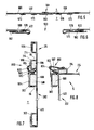
- 1 to 3 consists essentially of a right longitudinal wall 2, a left longitudinal wall 102, two front end walls 6 and 106 forming an inlet opening 4 between them, two end walls 10 and 110 forming a rear exit opening 8, two between a longitudinal slot 12 leaving blanket parts 14 and 114 forming a ceiling, and an endless filter belt 20 running around the cabin in the longitudinal direction according to arrows 16 and 18 as the cabin floor.
- a transport device 22 is arranged above the cabin, with a transport chain 23, from which suspension devices 24 for objects hang through the longitudinal slot 12 between the two ceiling parts 14, 114 into the cabin space 5, in which the objects are sprayed with coating powder by a powder spraying device 26 that protrudes from outside through a slot 28 into the cabin space 5.
- the right end walls 6 and 10 are pivotally connected to the longitudinal wall 2 via hinges 30 and can be pivoted through 90 ° from the position shown, in which they delimit the cabin space 5, into an unfolded position in which their inner surfaces run in the same plane as the inner surface of the longitudinal wall 2, and directly adjoin this inner surface, as shown in FIG. 1 for the left longitudinal wall 102 and the end walls 106 and 110 pivotally connected thereto via hinges 130 is.
- the end walls 6, 106, 10, 110 each consist of a wall element 31 which is pivotally connected to the longitudinal wall 2 or 102 via the hinge 30 or 130 and has a cutout 32 on the end face, and a cutout 32 in this cutout 32 via hinges 36 with the one wall element 31 pivotally connected wing-like further wall element 34.
- the cutouts 32 in the wall elements 31 form the inlet opening 4 and the outlet opening 8 when the end walls 6, 106, 10, 110 are at 90 ° to the longitudinal walls 2, 102 in the folded Position are pivoted inwards by 90 °, the wing-like wall elements 34 being pivoted out of the cutouts 32 by 90 °, as shown for the right cabin side in FIG. 1 for the end walls 6 and 10.
- the direction of pivoting of the wing-like wall elements 34 is opposite to the direction of pivoting of the wall elements 31 with respect to the longitudinal walls 2 and 102.
- the ceiling part 14 is formed by a ceiling element which is pivotally attached to the longitudinal wall 2 by means of hinges 40 and which can be pivoted upwards by 90 ° between the illustrated folded position and into an expanded position.
- 1 shows the unfolded position for a ceiling element forming the ceiling part 114, which is connected to the longitudinal wall 102 so as to be pivotable by 90 ° by means of hinges 140.
- a wing-like Ceiling element 42 is pivotally attached to the front end face 46 of the ceiling part 14 via hinges 44 and can be pivoted by 90 ° relative to the latter between the illustrated unfolded position and a folded position, the latter being shown for the same wing-like ceiling element 42 on the left cabin side.
- This further wing-like ceiling element 42 on the left cabin side is pivotally connected to the left ceiling part 114 via hinges 44.
- a ceiling element 50 is fixed in place on the longitudinal walls 2 and 102 in such a way that the inside surface of the one ceiling element 50 is flush with the inside surface of the ceiling part 14 when the ceiling part 14 is 90 ° is pivoted upwards into the unfolded position, and the inner surface of the ceiling part 50 on the left cabin side is flush with the inner surface of the other ceiling part 114 when this is folded up into the unfolded position as shown in FIG. 1.
- the ceiling part 14 and the wall elements 31 of the end walls 6 and 10 are shown in folded positions, in which they delimit the cabin space 5, so that an object can be coated therein by the spray device 26.
- the ceiling part 114 and the wall parts 31 of the end walls 106 and 110 are shown in unfolded positions, in which their inner surfaces 152, 154 and 156 run in the same plane as the inner surface 158 of the left longitudinal wall 102 and without large space, that is, border it as directly as possible.
- the wing-like wall elements 34 and ceiling elements 42 and the stationary ceiling elements 50 are also in a position in FIG which their inner surfaces 160, 162 and 164 run in the same plane as the inner surface 158 of the longitudinal wall 102, and each directly adjoin adjacent inner surfaces, such that all inner surfaces together form a self-contained, but porous, rectangular total surface, which can be sucked over this total area by a suction nozzle 166 by driving it once, and powder particles can thereby be cleaned.
- the suction nozzle 166 In its starting position, the suction nozzle 166 is located above the ceiling part 114 of the left longitudinal wall 102 which is pivoted upwards into the unfolded position and extends over the entire length of the total area of all inner surfaces 158, 154, 156, 160, 162, 152 located in one plane , 164, and is suctioned off this total area by two transport trains 168 and 170 by a motor 172 over the entire area down to the filter belt 20, which forms the cabin floor, down and then back up again.
- the suction nozzle 166 and its transport device 168 and 170, 172 are part of a suction device 174.
- a suction device 174 is provided in an identical manner for the longitudinal wall 2 shown on the right in FIG. 1 and the wall elements and ceiling elements 6, 10, 14, 42, which can be pivoted relative thereto, and the element 50, of which, however, only a rear transport train 70 in FIG. 1 is shown so that the display remains clear.
- the same reference numerals are used for the corresponding parts of the left cabin side as on the right cabin side, but increased by 100 on the left side.
- Actuators are provided for pivoting the pivotable wall elements and ceiling elements, of which 1, an actuator 80 for the ceiling element 14 is shown.
- the actuator can be operated electrically, pneumatically or hydraulically.
- the actuator 80 and the suction devices 174 are preferably connected to an automatic control device (not shown), by which the cleaning of the powder coating booth is triggered automatically before changing to another type of powder.
- the longitudinal walls 2 and 102 and the end walls 6, 106, 10, 110 which can be pivoted relative thereto and also ceiling parts 14, 114 which can also be pivoted relative to the longitudinal walls are each one-piece or multi-part elements which are each formed from a frame 84 and a cloth 86 stretched thereon .
- the frames preferably consist of U-shaped profile bars, the free leg ends 88 of which are directed towards the cabin space, at least when the elements are in their pivoted-out position corresponding to the left side of FIG. 1, so that the suction nozzle 166 never faces a completely closed surface. but can suck in air from the cavities 90 of the profile bars if it is located directly on the profile bars.
- the cloth 86 can be hooked onto hooks 92 in the upper part of the frame 84 and can be stretched by spring-elastic elements 94 around the lower part of the frame 84 so that, at least in the unfolded state of the elements, it is smooth and snug on the frame without folds 84 rests. 2, the cloth 86 is shown only for a clear illustration at a small distance from the frame 84, in reality it lies directly on the frame. As can be seen from FIG. 1 in particular with reference to the right side wall 2, the cloth 86 is located within the frame 84 on its side facing the cabin space 5.
- a Velcro fastener 97 can be provided in accordance with FIG. 3.
- the slot can be "buttoned” with this. So that the slit 28 remains open when the Velcro fastener 97 is open, a second Velcro fastener 98 can be provided on the side of the one slit edge 96 facing away from it, which holds this edge 96 in the open position when it is pushed back according to an arrow 99.
- FIGS. 4 to 8 The further embodiment of a powder coating system according to the invention shown in FIGS. 4 to 8 has on the left side a left longitudinal wall 202, to which a front end wall 206 and a rear end wall 210 are connected, each pivotable about a vertical axis.
- the two end walls 206 and 210 each consist of a wall element 231 pivotably connected to the longitudinal wall 202 and a wing 234 in a cutout of the wall element 231.
- the wall element 231 and the wing 234 together form an overall rectangular end wall 206 or 210.
- a ceiling part 214 is attached, pivotable about a horizontal axis.
- the elements 202, 231, 234 and 214 each consist of a frame 302, 331, 334 and 314, which are pivotally connected to one another in the manner mentioned, and of cloths which are arranged on the side of the frame facing the cabin space 5.
- a cloth 402 extends over both frames 302 and 314 of the left longitudinal wall 202 and the upper ceiling part 214.
- a second cloth 406 extends over the wall element 231 and the wing 234 of the front end wall 206.
- a third cloth 410 extends over the wall element 231 and the wing 234 of the rear end wall 210.
- the two end walls 206 and 210 extend over the entire height of the left longitudinal wall 202 and of the adjoining, upwardly opened ceiling part 214 corresponding to FIG. 4.
- the first cloth 402 of the left longitudinal wall 202 is releasably connected to the second cloth 406 of the front end wall 206 via a zipper 506 and releasably connected to the third cloth 410 of the rear end wall 210 via a zipper 510. So that the wing 234 can be pivoted out of the plane of the wall element 231 about a vertical pivot axis 235, there is in the cloth 406 and 410 between the two elements each formed a horizontal cut, the cutting edges of which are detachably connected to one another by a zip fastener 534.
- the floor of the cabin space 5 is formed by a continuous, endless filter belt 20.
- the left longitudinal wall 202 and the end walls 206 and 210 are located a short distance above the filter belt 20 close to its left longitudinal edge.
- all the elements form a smooth rectangular inner surface 600 of the cabin space 5 over its entire height , whose lower edge 602 and upper edge 604 extends a suction nozzle 266.
- the suction nozzle 266 sucks paint powder residues and dirt both from the inner surface 600 and at the same time at the lower edge 602 and at the upper edge 604 from the frames of the individual elements.
- the suction nozzle 266 hangs on a rail 606, so that it can lie against the cloths 402, 406 and 410 during the suction process, since it is on the rail 606 transversely to the plane of the cloths 402, 406 and 410, but not in the longitudinal direction of the cabin, " commute ".
- the suction nozzle 266 can be moved along the inner surface 600 by a motor 608 via a pulling element 610 over the entire length of the cabin space 5.
- the starting position of the suction nozzle 266 is located outside the cabin space 5 below the arrow 614 drawn in FIG. 4.
- Two vertical slots 561 and 563 which can be closed by a zipper 500 and 562, are formed in the cloth 402.
- a powder spray device 226 can be introduced into the cabin space 5 through these slots, of which the slot 563 is shown in the open state.
- FIG. 5 shows the slot 561 with the zipper 560 closed.
- the zipper 560 is located on the outside of the cabin 7 facing away from the cabin space 5.
- FIG. 6 shows the slot 563 with the zipper 562 open.
- Velcro elements 570 and 572 By means of Velcro elements 570 and 572, the ones with the zippers 560 and 562 provided edges of the slots 561 and 563 in the state shown in FIG. 6 to be attached to the cloth 402.
- FIG. 7 and 8 show the frame 302 of the left longitudinal wall 202 and the frame 314 of the left ceiling element 214, which are pivotally connected to one another via a joint 580 with a horizontal pivot axis 582.
- the frames 302 and 314 consist of U-shaped profile elements 584 and 586.
- the mutually adjacent components 584 and 586, which are connected to one another via the joint 580, are filled with an air-permeable, elastically compressible foam 588, which over the free leg ends 88 Components survives.
- the foam pads 588 are so soft that they can be pressed together a little by the stretched cloth 402 in order to compensate for alignment tolerances of the U-shaped components.
- FIG. 7 shows the ceiling element 214 in an upwardly folded position corresponding to FIG. 4.
- FIG. 8 shows the ceiling element 214 in a horizontal position pivoted to the right by 90 °, which is required when a workpiece with the powder spraying device in the cabin space 5 226 is coated.
- Fig. 8 is comparable to the longitudinal wall 2 shown in Fig. 1 on the right side and the elements pivoted inward by 90 ° relative thereto. Since the pivot axis 582 is arranged outside the inner surface 600, on the outside of the cabin 7, the cloth 402 would get waves if it is pivoted by 90 ° from FIG. 7 to FIG. 8. In order to keep the cloth 402 in a tensioned smooth state even in the position shown in FIG.
- a tensioning device 800 with a rubber band 802 is provided, which pulls the cloth 402 according to the representation of FIG. 8 towards the pivot axis 582 when that Ceiling element 214 is pivoted from the vertical position shown in FIG. 7 into the horizontal position shown in FIG. 8.
- One end of the band 802 is attached to the frame 314 of the ceiling member 214, and the other end of the band 802 is passed between the frame 314 of the ceiling member 214 and the frame 302 of the left longitudinal wall 202 and attached to the cloth 402.
- the rubber band 802 is guided over a roller 804 which is rotatably attached to the frame 302 and is arranged eccentrically to the pivot axis 582.
Landscapes
- Details Or Accessories Of Spraying Plant Or Apparatus (AREA)
- Paints Or Removers (AREA)
- Manufacturing Of Micro-Capsules (AREA)
- Coating Apparatus (AREA)
- Electrostatic Spraying Apparatus (AREA)
- Fertilizers (AREA)
Claims (15)
- Cabine pour le revêtement à l'aide de poudre, comprenant des éléments de paroi qui forment au moins deux parois longitudinales (2, 102 ; 202) disposées parallèlement entre elles et à distance l'une de l'autre, et comprenant au moins un élément de plafond (14, 114 ; 214), lesdits éléments de paroi et de plafond étant poreux et perméables à l'air et délimitant entre eux par leurs surfaces intérieures un volume intérieur de cabine (5),
caractérisée :- par le fait que certains des éléments (31, 34, 42, 14, 114 : 214, 231, 234) peuvent pivoter par rapport aux autres éléments (2, 102 ; 202) depuis une position repliée (partie de droite de la figure 1) dans laquelle ils forment le volume intérieur (5) de la cabine jusqu'a une position dépliée (côté de gauche de la figure 1),- et par le fait que, dans la position dépliée, les surfaces intérieures (152, 154, 156, 158, 160, 162, 164 ; 600) de tous les éléments (2, 14, 31, 34, 42, 50, 102, 114 202, 214, 231, 234) sont réparties au total sur deux plans à l'intérieur desquels elles s'étendent et constituent dans chaque plan une surface d'ensemble, pour l'essentiel ininterrompue, qui peut être balayée et aspirée par une unité d'aspiration (165 : 266), cependant que, dans cette position dépliée, la surface intèrieure (58 ; 600) de l'une des parois longitudinales (2 ; 202) s'étend dans l'un des plans et la surface intérieure (158) de l'autre paroi longitudinale (102) s'étend dans l'autre plan. - Cabine pour le revêtement à l'aide de poudre selon la revendication 1, caractérisée par au moins un vérin (80) à actionnement électrique, pneumatique ou hydraulique destiné à faire pivoter les éléments (14, 114, 31, 34, 42 ; 231, 234, 214) qui peuvent pivoter entre les deux positions.
- Cabine pour le revêtement à l'aide de poudre selon la revendication 1 ou 2, caractérisée par le fait qu'il est prévu pour chaque plan au moins une buse d'aspiration (166 ; 266) qui présente une longueur recouvrant la totalité de la largeur ou la totalité de la longueur de toutes les surfaces intérieures (158, 154, 160, 152, 152, 164, 156 ; 600) s'étendant dans le plan concerné et qui est montée mobile, transversalement par rapport à sa longueur, sur les surfaces intérieures s'étendant dans le plan concerné.
- Cabine pour le revêtement à l'aide de poudre selon l'une des revendications 1 à 3, caractérisée par le fait que les éléments pivotants (31, 34, 42, 14, 114 ; 214, 231, 234) peuvent pivoter de 90° environ par rapport aux éléments fixes (2, 102 ; 202).
- Cabine pour le revêtement à l'aide de poudre selon l'une des revendications 1 à 4, caractérisée par le fait que certains des éléments de paroi pivotants (31, 34 ; 231, 234) constituent des parois frontales (6, 106, 10, 110, ; 206, 210) du volume intérieur (5) de la cabine.
- Cabine pour le revêtement à l'aide de poudre selon la revendication 5, caractérisée par le fait que les parois frontales (6, 106, 10, 110, ; 206, 210) se composent à chaque fois d'au moins deux éléments de paroi (31, 34, 231. 234) qui sont reliés entre eux de manière pivotante et dont l'un est à chaque fois relié de manière pivotante à l'une des parois longitudinales (2, 102 ; 202).
- Cabine pour le revêtement à l'aide de poudre selon l'une des revendications 1 à 6 caractérisée par le fait que le plafond (14, 114 ; 214) est constitué par au moins deux éléments de plafond (14, 114 ; 214) dont l'un est relié de manière pivotante à l'une des parois longitudinales (2 ; 202) et dont l'autre est relié de manière pivotante à l'autre paroi longitudinale (102).
- Cabine pour le revêtement à l'aide de poudre selon l'une des revendications 1 à 7, caractérisée par le fait que la surface d'ensemble dans chaque plan est au total rectangulaire lorsque les éléments dépliables sont basculés dans le plan associé.
- Cabine pour le revêtement à l'aide de poudre selon l'une des revendications 1 à 8, caractérisée par le fait que les éléments sont constitués pour l'essentiel par un matériau perméable à l'air (86 ; 402, 406, 410).
- Cabine pour le revêtement à l'aide de poudre selon la revendication 9, caractérisée par le fait que les éléments sont à chaque fois constitués par un cadre (84 ; 302, 314, 331, 334) et par une toile (86 ; 402, 406, 410) ou par un matériau de paroi flexible et perméable à l'air analogue à une toile qui y est fixé et qui s'étend sur le cadre d'au moins un élément.
- Cabine pour le revêtement à l'aide de peudre selon la revendication 10, caractérisée par le fait que le cadre (84 ; 235, 302, 314, 331) est à chaque fois formé par des barres profilées en forme de U dont les extrémités libres des ailes (88) sont dirigées vers le volume intérieur (5) de la cabine, du moins lorsque les éléments s'étendent dans les deux plans dans la position dépliée (côté de gauche sur la figure 1).
- Cabine pour le revêtement à l'aide de poudre selon la revendication 11, caractérisée par le fait que sont disposés dans les barres profilées en forme de U des coussins élastiquement compressibles (588), de préférence en un produit alvéolaire, qui font saillie au-delà des extrémités libres des ailes (88) des barres profilées et qui supportent la toile ou le matériau analogue à une toile (86 ; 402, 406, 410), et par le fait que le coussin (588), sur sa surface qui supporte la toile ou le matériau analogue à une toile, est perméable à l'air, et présente de préférence des pores ouverts.
- Cabine pour le revêtement à l'aide de poudre selon l'une des revendications 10 à 12, caractérisée par le fait que les parties de toile (402, 406, 410) d'au moins deux éléments de paroi voisins (202, 214, 231, 234) sont reliées entre elles de manière amovible par un élément de fermeture, et de préférence par une fermeture à glissière (506, 510, 534).
- Cabine pour le revêtement à l'aide de poudre selon l'une des revendications 10 à 13, caractérisée par le fait que, dans l'une au moins des deux parois longitudinales (202), il est formé dans la toile (402) d'au moins un élément de paroi (202) une fente (561, 563) par laquelle un dispositif de poudrage (226) peut être introduit dans le volume intérieur (5) de la cabine en passant à travers la paroi longitudinale, et par le fait que les bords de cette fente sont reliés entre eux de manière amovible par un élément de fermeture, et de préférence par une fermeture à glissière (560. 562).
- Cabine pour le revêtement à l'aide de poudre selon l'une des revendications 10 à 14, caractérisée par au moins un dispositif de tension (800) pour tendre la toile ou le matériau analogue à une toile (402), lequel tire la toile ou le matériau analogue à une toile (402) vers l'extérieur, dans la direction opposée au volume intérieur (5) de la cabine, entre deux éléments reliés entre eux de manière pivotante (202, 214), en maintenant grâce à cela les parties de toile des deux éléments dans un état tendu et plat, même lorsque les éléments ont pivoté l'un par rapport à l'autre, et en particulier lorsqu'ils ont pivoté depuis un angle formé entre eux de 180° jusqu'à un angle formé entre eux de 90°.
Priority Applications (1)
| Application Number | Priority Date | Filing Date | Title |
|---|---|---|---|
| AT88104738T ATE63842T1 (de) | 1987-04-11 | 1988-03-24 | Pulverbeschichtungskabine. |
Applications Claiming Priority (2)
| Application Number | Priority Date | Filing Date | Title |
|---|---|---|---|
| DE19873712437 DE3712437A1 (de) | 1987-04-11 | 1987-04-11 | Pulverbeschichtungskabine |
| DE3712437 | 1987-04-11 |
Publications (3)
| Publication Number | Publication Date |
|---|---|
| EP0286885A2 EP0286885A2 (fr) | 1988-10-19 |
| EP0286885A3 EP0286885A3 (en) | 1989-09-27 |
| EP0286885B1 true EP0286885B1 (fr) | 1991-05-29 |
Family
ID=6325504
Family Applications (1)
| Application Number | Title | Priority Date | Filing Date |
|---|---|---|---|
| EP88104738A Expired - Lifetime EP0286885B1 (fr) | 1987-04-11 | 1988-03-24 | Cabine pour le revêtement à l'aide de poudre |
Country Status (5)
| Country | Link |
|---|---|
| US (1) | US4851261A (fr) |
| EP (1) | EP0286885B1 (fr) |
| JP (1) | JPH0667497B2 (fr) |
| AT (1) | ATE63842T1 (fr) |
| DE (2) | DE3712437A1 (fr) |
Families Citing this family (14)
| Publication number | Priority date | Publication date | Assignee | Title |
|---|---|---|---|---|
| US5107789A (en) * | 1989-02-01 | 1992-04-28 | Blodgett & Blodgett, P.C. | Article coating system |
| DE3919614A1 (de) * | 1989-06-15 | 1990-12-20 | Gema Ransburg Ag | Anlage zum elektrostatischen spruehbeschichten mit pulver |
| DE8907538U1 (de) * | 1989-06-16 | 1990-10-18 | Farb-Tec Gesellschaft für Beschichtungskabinen-Systeme mbH, 2000 Hamburg | Kabine zum Sprühbeschichten von Gegenständen mit pulverförmigem Beschichtungsmaterial |
| DE4131287A1 (de) * | 1991-09-20 | 1993-03-25 | Gema Volstatic Ag | Pulver-spruehbeschichtungsanlage |
| DE9203367U1 (de) * | 1992-03-10 | 1992-08-27 | Farb-Tec Gesellschaft für Beschichtungskabinen Systeme mbH, 2000 Hamburg | Reinigungsvorrichtung für eine Kabine zum Sprühbeschichten von Werkstücken mit pulverförmigen Beschichtungsmaterial |
| DE4300837A1 (de) * | 1993-01-14 | 1994-07-21 | Gema Volstatic Ag St Gallen | Pulver-Sprühbeschichtungsanlage |
| DE19500872B4 (de) * | 1995-01-13 | 2005-10-27 | Itw Gema Ag | Pulver-Sprühbeschichtungsvorrichtung |
| US5833751A (en) * | 1996-10-18 | 1998-11-10 | Hoosier Fiberglass Industries, Inc | Powder coating booth having smooth internal surfaces |
| US6264711B1 (en) * | 1999-11-24 | 2001-07-24 | William Smith | Capture of liquid sanding dust atomized overspray blast media and other errant particles in an unenclosed area |
| US6669780B2 (en) | 2000-10-24 | 2003-12-30 | Illinois Tool Works Inc. | Color change booth |
| US20020046702A1 (en) * | 2000-10-24 | 2002-04-25 | James M. Browning | Powder coating system and method for quick color change |
| ES2294668T3 (es) * | 2004-03-30 | 2008-04-01 | J. Wagner Ag | Dispositivo y procedimiento para limpiar una cabina de aplicacion de revestimientos en polvo. |
| US7550022B2 (en) * | 2006-06-22 | 2009-06-23 | Smith William C | Portable system for capturing air pollution |
| DE102012004704A1 (de) | 2012-03-07 | 2013-09-12 | Eisenmann Ag | Verfahren und Vorrichtung zum Abführen von mit Overspray beladener Prozessluft sowie Anlage zum Beschichten von Gegenständen |
Family Cites Families (17)
| Publication number | Priority date | Publication date | Assignee | Title |
|---|---|---|---|---|
| US2594957A (en) * | 1952-04-29 | Multiple unit self-cleaning dust | ||
| DE448489C (de) * | 1925-12-29 | 1927-08-20 | Sprimag Spritzmaschinen Bau Ge | Kreislaufventilation mit gesteuerter Luftstroemung |
| DE970777C (de) * | 1953-02-28 | 1958-10-30 | Alfred Teufel | Luftleitvorrichtung fuer Raeume, durch die vorzugsweise Luft von oben nach unten stroemt, insbesondere Farbsprltz- und Trockenkabinen |
| CH475800A (de) * | 1967-04-24 | 1969-07-31 | Froehlich Albert | Mobile Spritzkabine |
| US3564845A (en) * | 1968-09-19 | 1971-02-23 | Thiokol Chemical Corp | Membrane seal assembly for use with solid propellant rocket motors having selective zoning capabilities |
| GB1357354A (en) * | 1970-09-28 | 1974-06-19 | Hardy S | Means and methods for trapping paint |
| US3810350A (en) * | 1972-04-24 | 1974-05-14 | American Air Filter Co | U-shaped fluid treating filter |
| US3815342A (en) * | 1972-05-03 | 1974-06-11 | Curtiss Wright Corp | Gas filter assembly |
| CH560558A5 (en) * | 1973-10-31 | 1975-04-15 | Elfag Holding | Electrostatic spray coater booth - air curtain over inwall leads out to blower suction-side outlet |
| DE2449065A1 (de) * | 1974-10-15 | 1976-04-29 | Luft Und Trockentechnik Kg Sch | Filterdecke fuer lackier- und trockenkabinen o.dgl. |
| SE424606B (sv) * | 1978-12-06 | 1982-08-02 | Loeoef Ingemar | Sprutbox |
| DE2926040C2 (de) * | 1979-06-28 | 1982-07-15 | Ernst St.Gallen Lehmann | Sprühbeschichtungskabine für pulverförmiges bis körniges Beschichtungsmaterial |
| DE3015929A1 (de) * | 1980-04-25 | 1981-11-05 | Ernst St.Gallen Lehmann | Kabine zur pulver-spruehbeschichtung |
| DE8314662U1 (de) * | 1983-05-18 | 1986-05-28 | Becker, Martin, 3108 Winsen | Einrichtung zum Beschichten von Gegenständen |
| US4509961A (en) * | 1983-06-17 | 1985-04-09 | Armstrong Jones Inc. | Air filter assembly |
| DE3500005A1 (de) * | 1985-01-02 | 1986-07-10 | ESB Elektrostatische Sprüh- und Beschichtungsanlagen G.F. Vöhringer GmbH, 7758 Meersburg | Beschichtungskabine zum ueberziehen der oberflaeche von werkstuecken mit beschichtungspulver |
| EP0212091A1 (fr) * | 1985-06-10 | 1987-03-04 | INTERATOM Gesellschaft mit beschränkter Haftung | Turbo-soufflante avec un palier aérostatique |
-
1987
- 1987-04-11 DE DE19873712437 patent/DE3712437A1/de not_active Withdrawn
-
1988
- 1988-03-24 AT AT88104738T patent/ATE63842T1/de not_active IP Right Cessation
- 1988-03-24 DE DE8888104738T patent/DE3862991D1/de not_active Expired - Fee Related
- 1988-03-24 EP EP88104738A patent/EP0286885B1/fr not_active Expired - Lifetime
- 1988-04-01 JP JP63082127A patent/JPH0667497B2/ja not_active Expired - Lifetime
- 1988-04-07 US US07/178,522 patent/US4851261A/en not_active Expired - Fee Related
Also Published As
| Publication number | Publication date |
|---|---|
| US4851261A (en) | 1989-07-25 |
| ATE63842T1 (de) | 1991-06-15 |
| DE3862991D1 (de) | 1991-07-04 |
| EP0286885A3 (en) | 1989-09-27 |
| DE3712437A1 (de) | 1988-10-20 |
| JPS63267470A (ja) | 1988-11-04 |
| EP0286885A2 (fr) | 1988-10-19 |
| JPH0667497B2 (ja) | 1994-08-31 |
Similar Documents
| Publication | Publication Date | Title |
|---|---|---|
| EP0286885B1 (fr) | Cabine pour le revêtement à l'aide de poudre | |
| DE69007630T2 (de) | Hohlraum bildende Faltjalousie. | |
| DE19544615A1 (de) | Zusammenlegbarer Laufstall | |
| DE4126891A1 (de) | Elektrostatische pulver-spruehbeschichtungsanlage fuer automobil-karosserien | |
| DE69403485T2 (de) | Vorrichtung zum überkopfsprühen oder seitlichen sprühen von beschichtungsmittel | |
| EP0517143A2 (fr) | Table de transport pour des matériaux plats comme du tissu, des feuilles ou des matériaux similaires | |
| DE29711352U1 (de) | Führungsanordnung für ein Türelement | |
| EP1125639B1 (fr) | Cabine de poudrage de pièces | |
| DE2947755A1 (de) | Spritzkabine | |
| DE4106117C2 (de) | Schiebetürführung, insbesondere für Duschabtrennungen und dgl. | |
| DE10300130A1 (de) | Halterung für Waren im Laderaum eines Fahrzeugs | |
| DE69921177T2 (de) | Gelenk | |
| DE69935746T2 (de) | Reinigungsgerät, Reinigungstuch und Verfahren zum Reinigen | |
| DE19925938C2 (de) | Rüttelsieb | |
| EP1082935B1 (fr) | Paravent | |
| DE3509115A1 (de) | Dusch- oder brausebadabtrennung | |
| EP0458084A1 (fr) | Elément filtrant | |
| DE10247242B3 (de) | Koffer | |
| DE8907540U1 (de) | Kabine zum Sprühbeschichten von Gegenständen mit pulverförmigem Beschichtungsmaterial | |
| DE29509285U1 (de) | Zusammenklappbares Reisebett, insbesondere Kinderreisebett, o.dgl. | |
| DE3125359A1 (de) | Halterung fuer faltbare fluegelanordnungen, insbesondere fuer falttueren an moebelstuecken | |
| DE19737790C1 (de) | Aus dem Kofferraum eines Fahrzeuges ausklappbarer Außensitz | |
| DE2847656C2 (fr) | ||
| DE3221498C2 (de) | Vorrichtung zum Betätigen eines Vorhanges für Fenster und Türen | |
| DE1929015A1 (de) | Schlitzluefter fuer den Einbau in Gebaeudedecken |
Legal Events
| Date | Code | Title | Description |
|---|---|---|---|
| PUAI | Public reference made under article 153(3) epc to a published international application that has entered the european phase |
Free format text: ORIGINAL CODE: 0009012 |
|
| 17P | Request for examination filed |
Effective date: 19880324 |
|
| AK | Designated contracting states |
Kind code of ref document: A2 Designated state(s): AT CH DE ES FR GB IT LI SE |
|
| PUAL | Search report despatched |
Free format text: ORIGINAL CODE: 0009013 |
|
| AK | Designated contracting states |
Kind code of ref document: A3 Designated state(s): AT CH DE ES FR GB IT LI SE |
|
| 17Q | First examination report despatched |
Effective date: 19900827 |
|
| GRAA | (expected) grant |
Free format text: ORIGINAL CODE: 0009210 |
|
| AK | Designated contracting states |
Kind code of ref document: B1 Designated state(s): AT CH DE ES FR GB IT LI SE |
|
| PG25 | Lapsed in a contracting state [announced via postgrant information from national office to epo] |
Ref country code: IT Free format text: LAPSE BECAUSE OF FAILURE TO SUBMIT A TRANSLATION OF THE DESCRIPTION OR TO PAY THE FEE WITHIN THE PRESCRIBED TIME-LIMIT;WARNING: LAPSES OF ITALIAN PATENTS WITH EFFECTIVE DATE BEFORE 2007 MAY HAVE OCCURRED AT ANY TIME BEFORE 2007. THE CORRECT EFFECTIVE DATE MAY BE DIFFERENT FROM THE ONE RECORDED. Effective date: 19910529 Ref country code: ES Free format text: THE PATENT HAS BEEN ANNULLED BY A DECISION OF A NATIONAL AUTHORITY Effective date: 19910529 Ref country code: SE Effective date: 19910529 |
|
| REF | Corresponds to: |
Ref document number: 63842 Country of ref document: AT Date of ref document: 19910615 Kind code of ref document: T |
|
| RAP2 | Party data changed (patent owner data changed or rights of a patent transferred) |
Owner name: GEMA VOLSTATIC AG |
|
| GBT | Gb: translation of ep patent filed (gb section 77(6)(a)/1977) | ||
| REF | Corresponds to: |
Ref document number: 3862991 Country of ref document: DE Date of ref document: 19910704 |
|
| ET | Fr: translation filed | ||
| PG25 | Lapsed in a contracting state [announced via postgrant information from national office to epo] |
Ref country code: AT Effective date: 19920324 |
|
| PG25 | Lapsed in a contracting state [announced via postgrant information from national office to epo] |
Ref country code: LI Effective date: 19920331 Ref country code: CH Effective date: 19920331 |
|
| PLBE | No opposition filed within time limit |
Free format text: ORIGINAL CODE: 0009261 |
|
| STAA | Information on the status of an ep patent application or granted ep patent |
Free format text: STATUS: NO OPPOSITION FILED WITHIN TIME LIMIT |
|
| 26N | No opposition filed | ||
| REG | Reference to a national code |
Ref country code: CH Ref legal event code: PL |
|
| PGFP | Annual fee paid to national office [announced via postgrant information from national office to epo] |
Ref country code: DE Payment date: 19930311 Year of fee payment: 6 |
|
| PGFP | Annual fee paid to national office [announced via postgrant information from national office to epo] |
Ref country code: GB Payment date: 19930312 Year of fee payment: 6 |
|
| PGFP | Annual fee paid to national office [announced via postgrant information from national office to epo] |
Ref country code: FR Payment date: 19930318 Year of fee payment: 6 |
|
| PG25 | Lapsed in a contracting state [announced via postgrant information from national office to epo] |
Ref country code: GB Effective date: 19940324 |
|
| GBPC | Gb: european patent ceased through non-payment of renewal fee |
Effective date: 19940324 |
|
| PG25 | Lapsed in a contracting state [announced via postgrant information from national office to epo] |
Ref country code: FR Effective date: 19941130 |
|
| PG25 | Lapsed in a contracting state [announced via postgrant information from national office to epo] |
Ref country code: DE Effective date: 19941201 |
|
| REG | Reference to a national code |
Ref country code: FR Ref legal event code: ST |