EP0286888A1 - Système de régulation de la température - Google Patents
Système de régulation de la température Download PDFInfo
- Publication number
- EP0286888A1 EP0286888A1 EP88104810A EP88104810A EP0286888A1 EP 0286888 A1 EP0286888 A1 EP 0286888A1 EP 88104810 A EP88104810 A EP 88104810A EP 88104810 A EP88104810 A EP 88104810A EP 0286888 A1 EP0286888 A1 EP 0286888A1
- Authority
- EP
- European Patent Office
- Prior art keywords
- temperature
- heat pump
- output
- curves
- time
- Prior art date
- Legal status (The legal status is an assumption and is not a legal conclusion. Google has not performed a legal analysis and makes no representation as to the accuracy of the status listed.)
- Ceased
Links
- 230000007613 environmental effect Effects 0.000 claims abstract description 17
- 230000015654 memory Effects 0.000 claims description 17
- 238000011084 recovery Methods 0.000 claims description 7
- 238000005496 tempering Methods 0.000 claims description 2
- 230000006870 function Effects 0.000 description 10
- 238000010438 heat treatment Methods 0.000 description 6
- 238000001816 cooling Methods 0.000 description 5
- 230000001351 cycling effect Effects 0.000 description 3
- 230000003247 decreasing effect Effects 0.000 description 3
- 230000002596 correlated effect Effects 0.000 description 2
- 239000004020 conductor Substances 0.000 description 1
- 230000001276 controlling effect Effects 0.000 description 1
- 238000010586 diagram Methods 0.000 description 1
- 238000004134 energy conservation Methods 0.000 description 1
- 238000005265 energy consumption Methods 0.000 description 1
- 238000005516 engineering process Methods 0.000 description 1
- 230000005855 radiation Effects 0.000 description 1
- 230000004044 response Effects 0.000 description 1
- 238000010977 unit operation Methods 0.000 description 1
Images



Classifications
-
- G—PHYSICS
- G05—CONTROLLING; REGULATING
- G05D—SYSTEMS FOR CONTROLLING OR REGULATING NON-ELECTRIC VARIABLES
- G05D23/00—Control of temperature
- G05D23/19—Control of temperature characterised by the use of electric means
- G05D23/1902—Control of temperature characterised by the use of electric means characterised by the use of a variable reference value
- G05D23/1904—Control of temperature characterised by the use of electric means characterised by the use of a variable reference value variable in time
-
- F—MECHANICAL ENGINEERING; LIGHTING; HEATING; WEAPONS; BLASTING
- F24—HEATING; RANGES; VENTILATING
- F24D—DOMESTIC- OR SPACE-HEATING SYSTEMS, e.g. CENTRAL HEATING SYSTEMS; DOMESTIC HOT-WATER SUPPLY SYSTEMS; ELEMENTS OR COMPONENTS THEREFOR
- F24D19/00—Details
- F24D19/10—Arrangement or mounting of control or safety devices
- F24D19/1006—Arrangement or mounting of control or safety devices for water heating systems
- F24D19/1009—Arrangement or mounting of control or safety devices for water heating systems for central heating
- F24D19/1039—Arrangement or mounting of control or safety devices for water heating systems for central heating the system uses a heat pump
-
- G—PHYSICS
- G05—CONTROLLING; REGULATING
- G05D—SYSTEMS FOR CONTROLLING OR REGULATING NON-ELECTRIC VARIABLES
- G05D23/00—Control of temperature
- G05D23/19—Control of temperature characterised by the use of electric means
- G05D23/1919—Control of temperature characterised by the use of electric means characterised by the type of controller
Definitions
- the present invention relates to a temperature control system according to the preamble of claim 1.
- the present invention is directed to a temperature control system for a multiplant environmental unit wherein a microcomputer or microprocessor based thermostat is utilized.
- the invention has particular utility with heat pumps that are operated in conjunction with auxiliary electric heat.
- the electric heat typically provides a very high cost penalty in its use over the heat pump itself.
- the present system or invention is utilized in a setback type of thermostat wherein a lowered temperature during a night or unoccupied period is utilized for energy savings, and then the temperature is setup to a normal comfort temperature.
- the setup function is controlled by the present invention in a manner that provides a high degree of efficiency in the use of the heat pump and auxiliary heat, as well as providing a good response of the control temperature between the setback temperature level and the desired comfort temperature level.
- the temperature controlled system has two separate modes of operation.
- the first mode of operation utilizes a temperature ramp rate to control the heat pump and provides for a second ramp rate for control of the auxiliary electric heat. These two ramp rates are maintained parallel to one another but separated by a fixed number of degrees.
- the heat pump is utilized in its maximum operating capacity and the auxiliary electric heat is occasionally cycled in order to meet the heating demand required to raise the temperature from the setback temperature to the desired comfort temperature.
- a second mode of operation on which comes into operation when extremely cold conditions exist, utilizes a pair of ramp rates, but the two ramp rates are not maintained in a parallel relationship. In this second mode of operation, the heat pump ramp rate is set to some minimum slope thereby indicating a cold exterior, and the auxiliary heat ramp rate is adjusted to control the auxiliary heat into operation in a substantially larger percent of time than is present during the first mode of operation.
- the slope of the ramp rates is adjusted after each cycle based on the previous cycles events.
- the memory in the microcomputer is programmed to take the previous cycle into consideration in determining the position or slope of the ramp rates in an upcoming temperature cycle.
- a multiplant environmental unit 10 made up of a heat pump 11 and electric auxiliary heat 12.
- the heat pump 11 and auxiliary heat 12 provide heat (and cooling on the reverse cycle) via channels 13 and 14 to a distribution network 15.
- the distribution network 15 includes such equipment as a blower and duct work, and provides heating and/or cooling through a channel 16 to a building or enclosed space 17.
- the building or enclosed space 17 typically would be a residential structure, and would be affected by weather 20.
- Weather 20 includes such things as solar radiation, winds, and outdoor temperature.
- thermostat means 21 within the building or enclosed space 17 is a real time clock operated thermostat means 21 that includes a microcomputer or microprocessor 22 and a memory 23.
- the thermostat means 21 also would include a clock means, which normally is part of the microprocessor or microcomputer 22.
- the thermostat means 21 is indicated as having at least two stages 24 and 25 that are capable of providing switched, on-off control signals to conductors 26 and 27 that are used to in turn control the heat pump 11 and the auxiliary electric heat 12.
- the thermostat means 21 is normally affected by the wall temperature 30 and the air temperature 31 of the building or enclosed space 17. To this point, a conventional heat pump and auxiliary heat arrangement for a building or residence incorporating the novel system has been described.
- the temperature control system or thermostat means 23 of Figure 1 is adapted to the present invention in a manner that will be disclosed subsequently.
- the operation of Figure 1 includes the operation of the thermostat means 21 to control temperature between a night setback temperature, for instance 15°C , and a normal daytime comfort temperature of, say 20°C.
- the thermostat means 21 has two stages that can be controlled to provide either the first or second modes of operation that were discussed in the foregoing specification.
- the first and second stages operate to pick up the temperature between the night setback temperature and the normal comfort temperature along a sloped ramp with the heat pump ramp and the auxiliary heat ramp being maintained parallel to one another. Their general slope varies from day-to-day depending on the conditions from the previous day.
- the heat pump 11 is controlled by the first stage of thermostat means 21, while the auxiliary electric heat 12 is controlled by the second stage of the thermostat means 21.
- the thermostat means 21 responds to the air temperature 31 and the wall temperature 30, while the enclosed building or space 17 is responsive to the outside weather 20 in combination with heat supplied through the distribution network 15 via the duct 16 in a conventional manner.
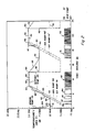
- Figures 2 through 5 disclose four graphs representing four different levels of operation of the temperature control system or thermostat means disclosed in Figure 1.
- the temperature control system operates the multiplant environmental unit 10 with either the operation of the heat pump 11, or the operation of the heat pump 11 and the auxiliary heat 12.
- the graphs of Figures 2 through 5 plot temperature in °C at 36 versus time in hours at 35. The time in hours also is plotted against the operation of the multiplant environmental unit operation at 37 indicating whether the heat pump 11 is on or off, and whether the auxiliary heat 12 is on or off. In this way, the temperature and the outputs from the multiplant environmental unit 10 can be correlated.
- the heat pump function is normally referred to as a first output and the auxiliary heat as a second output.
- thermostat means 21 of Figure 1 has a sensor means or sensor temperature that allows the thermostat means 21 to track the temperature within the building or enclosed space 17.
- the real time clock that is contained within the thermostat 21 allows for the programming of the memory within the thermostat means 21 to provide the curves within Figures 2 to 5 and which will now be described in some detail.
- the thermostat means 21 has programmed into it a desired setpoint temperature 40 that is used for energy conservation.
- the setpoint temperature 40 is maintained at 15°C as shown at 41 including an interval at zero time (which could be equated to midnight).
- the setpoint temperature 40 is ramped up at some preselected number of degrees per hour until about 6 a.m. in the morning.
- the setpoint temperature 40 is raised to the normal or selected comfort setpoint temperature of 20°C at 43. This represents the need to raise the temperature within the building or enclosed space 17 from some energy saving or setback setpoint temperature 41 to provide a comfortable ambient within the building 17 when the occupants are up for the day.
- the setpoint temperature 40 is set back down at 44 to an afternoon energy saving temperature of 17,5°C at 45 at approximately 10:00 in the morning.
- This second setback cycle is optional and can be used to save additional energy.
- the afternoon setback cycle has the same characteristics as the morning setback and pickup cycle and will be described only once in connection with the graphs of Figures 2 through 5.
- the afternoon setback or energy saving temperature 45 of 17,5°C is maintained until a second setback ramp intersected at 46.
- the setpoint temperature 40 could be ramped at the same rate in the morning as in the afternoon, or could be ramped at a different rate. The principle of operation, however, is the same.
- the setpoint temperature is raised at 47 to the selected comfort setpoint temperature of 20°C due to the operation of the system, but would reach that level at 48 regardless of operation by means of the real time clock and memory within the thermostat means 21.
- the setpoint temperature 40 is again lowered to 15°C as was indicated at 41.
- the cycle then repeats itself for the next day, but is adaptably changed based on whether or not the multiplant environmental unit 10 reached the desired temperature at the selected time. Changes in the operation of the multiplant environmental unit 10 are exemplified in four different conditions by the graphs of Figures 2 through 5.
- the setpoint temperature 40 is established by two different functions. First is the energy saving setback setpoint temperature 41 along with the selected comfort setpoint temperature at 43. Between these two points the setpoint temperature 40 is established by the slope of two operating time versus temperature curves that are identified as a heat pump ramp 51 and an auxiliary heat ramp 52.
- the auxiliary heat ramp 52 coincides with the setpoint temperature 40 over the range of 15°C to 19,25°C and then abrubtly changes to intersect at 43 where the setpoint temperature has been raised to the selected comfort setpoint temperature of 20°C.
- the heat pump ramp 51 is parallel to the auxiliary heat ramp 52 and separated by a fixed number of degrees. Ramp 51 intersects 20°C at 43 as a point of reference.
- the slope of the heat pump ramp 51 and the auxiliary heat ramp 52 is adjusted from day-to-day based on the history of the operation of the temperature control system as will be explained in connection with Figures 2 through 5.
- a preestablished first operating mode is used as a point of reference for an explanation of operation of the system and that operation will now relate how the actual temperature in the building or enclosed space 17 is correlated with the heat pump 11, the auxiliary heat 12, and the setpoint temperature 40.
- a sensor within the thermostat means 21 continuously measures the building or enclosed space temperature. This temperature is plotted as a sensor temperature 53. It is understood that when the setpoint temperature 40 was suddenly set down to 15°C at 10:00 at night at 50, that the building or enclosed space 17 was at 20°C and will drift down as shown at 54 after midnight. When the sensor temperature 53 drifts down and intersects at 55 the 15°C setpoint temperature 41, it will be noted that the heat pump 11 of the multiplant environmental unit 10 switches from an off state to an on state. The heat pump cycles, as shown at 56 and 57, to maintain the sensor temperature 53 at 15°C. At 60 the sensor temperature 53 intersects the heat pump ramp 51. At this point, the heat pump 11 is locked on as shown at 61 as the sensor temperature 53 rises at 62.
- the system is designed so that the locked on state of the heat pump 11 remains in the mode until the sensor temperature 53 exceeds the heat pump ramp 51 by some set number of degrees, or until the sensor comes within a specified value below the comfort setpoint. At that point, the heat pump is again deenergized. The sensor temperature drops at 63 to again intersect the heat pump ramp 51. This locks the heat pump 11 on at 64 and causes the sensor temperature 53 to rise again as shown at 65. Once again, as the sensor temperature 53 exceeds the heat pump ramp temperature 51 by some set number of degrees, the heat pump is again deenergized. This cycle continues to occur until the pickup time of 6:00 is reached at which time the setpoint temperature 40 is brought to 20°C. Once this occurs, the sensor temperature 53 (as shown at 66) continues to cycle the heat pump as shown generally at 67.
- the selected comfort setpoint temperature 40 (as indicated at 44 and 45) is set back down to 17,5°C.
- the sensor temperature 53 then drops off at 68 until the sensor temperature 53 intersects the setpoint temperature 40 at 70. This causes the heat pump to cycle as is indicated generally at 71 to maintain the 17,5°C temperature.
- the sensor temperature 53 rises until the 20°C comfort temperature has been reached at approximately 47, which is ahead of the intersection of the heat pump ramp 51 ⁇ and the comfort temperature at 48.
- the heat pump 11 is again cycled as generally shown at 72 to maintain the sensor temperature 53 as indicated at 73.
- the setback for night operation at approximately 10:00 occurs, and the sensor temperature 53 again slopes off as indicated at 74.
- the thermostat means 21 would recognize the fact that the heat pump had been locked on part of the time and exceeded the heat pump ramp 51 in comparing the sensor temperature 53 as was indicated at 62 and 65. This would cause the thermostat means 21 to increase the slope of auxiliary ramp 52 and the heat pump ramp 51. This adjustment would occur by making a change of approximately 12 percent in the rate of the slope thereby reducing the amount of time that the heat pump is on during the next cycle.
- the auxiliary electric heat 12 cycles as indicated generally at 79 to keep the sensor temperature 53 close to the setpoint temperature 40.
- the sensor temperature 53 is just close enough to the setpoint temperature 40 so that the cycling of the heat pump 11 alone can bring the sensor temperature 53 up to the setpoint temperature 40 at 44.
- the afternoon or daytime setback occurs and the afternoon sensor temperature 68 decays with the afternoon pickup occurring in the same fashion as has been explained in connection with Figure 2.
- the slope of the heat pump ramp 51 and the auxiliary ramp 52 has become shallower. This movement occurs until a preselected minimum slope is reached. When the preselected minimum slope is reached, the first mode of operation of the present system will end. The system will then shift to a second mode of operation, which is shown in Figure 5.
- the determination of whether or not the system is in the first or second mode is established by the thermostat means 21 recognizing, by means of the microprocessor and memory 23, what has happened in a previous cycle. When the previous cycle indicates that the mode one minimum slope has been reached, the system will shift automatically to the second mode of operation. Conversely, when in the second mode of operation, the thermostat means can recognize that the second mode is no longer necessary, and the system will shift from the second mode back to the first mode of operation.
- FIG. 5 the second mode of operation is disclosed.
- a heat pump ramp 80 and an auxiliary heat ramp 81 is disclosed.
- the heat pump ramp 80 is identical in nature to the heat pump ramp 51 of Figures 2 to 4.
- the auxiliary heat ramp 81 is, however, significantly different. It will be noted that the ramps are no longer parallel and that they both intersect at a common point 82.
- the common point 82 corresponds to point 43 of Figures 2 through 4 where the setpoint temperature 40 intersects the selected comfort setpoint temperature of 20°C at 6:00 in the morning.
- the heat pump ramp 80 and auxiliary heat ramp 81 are independent, and the heat pump ramp 80 is maintained at a minimum slope for the system.
- the auxiliary heat ramp 81 is then made very steep to delay the operation of the auxiliary heat, as will be explained.
- the heat pump 11 When the sensor temperature 53 again drifts down to intersect at 55 with the heat pump ramp 80, the heat pump 11 is locked on at 56. Under these cold conditions, the heat pump alone is unable to maintain the sensor temperature 53 at the 15°C temperature as shown at 82. As soon as the sensor temperature 53 intersects the auxiliary heat ramp 81 at 83, the auxiliary heat is cycled at 84 to keep the setpoint temperature 40 within a tolerance of the auxiliary heat ramp 81. This causes the sensor temperature 53 to rise as shown at 85 with the temperature sensed being very close to the auxiliary heat ramp 81. This allows for the building or enclosed space 17 to reach 20°C at a time very close to the 6:00 setup time as indicated at 82.
- the slope of the auxiliary ramp 81 can be modified to adjust for operation of the system.
- the auxiliary ramp slope increases if the sensor temperature is able to rise to some specified value below the comfort setpoint temperature at a time before or at the comfort time; otherwise the slope is decreased.
- the weather would have to warm up enough so that sensor temperature 53 rises to end the recovery at 82 without ever intersecting the ramped setpoint temperature 40 (coincident with the auxiliary heat ramp 81), and indicates that less electric heat is necessary.
- the system shifts back to mode one and the system continuously adjusts on a day-to-day basis based on past history thereby allowing the system to respond each day to change in outdoor temperature conditions without in fact ever having any sensor in the outside environment.
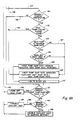
- Figures 6a and b is a flow chart of the operation of the temperature control system for control of a multiplant environmental unit 10 for tempering the atmosphere in an enclosed space or building 17 in an energy efficient manner.
- the flow chart of Figures 6a and b provides a complete disclosure of the invention, as was illustrated by the graphs of Figures 2 through 5.
- a normal operation of the system at a selected comfort temperature setpoint temperature is indicated at 100.
- the system determines at 101 whether the thermostat means 21 is in a setback mode. If not, the system cycles back to 100. If it is in a setback mode, the system controls the space temperature at the selected setback temperature.
- the establishment of a normal operation at a setback temperature at 102 then proceeds at 103 to determine whether the sensor temperature intersects the heat pump ramp. If that does occur, the heat pump is locked on at 104. If this does not occur, the system then moves to the decision block 105 to determine whether time is greater than the comfort time. The locked on heat pump inquiry of 104 then proceeds to the decision function at 105. If at 105 the time was not greater than the comfort time, the system proceeds at 107 and executes a program that will be disclosed in connection with Figure 6b.
- the logic determines at 106 whether the heat pump had cycled at any time after it was locked on at 104.
- the system proceeds at 108 to a portion of the program shown in Figure 6b. If it did not, a decision at 109 is made as to whether or not the heat pump in fact was used at all. If not, at 110, the system switches back to normal operation at 111. If it was operating, a decision is made at 112 whether the heat pump was activated using the minimum ramp rate. If it was, the auxiliary heat ramp rate is decreased and the heat pump ramp rate is left at the minimum value at 113. If it was not, the heat pump ramp rate is decreased at 114.
- the decision block at 115 determines whether the new heat pump ramp rate is at the minimum value. If so, at 116, the auxiliary heat ramp rate is set to its initial default value, and its future values are now independent of the heat pump ramp rate. If not, at 117 the auxiliary heat ramp rate has the same slope as the heat pump ramp rate. In each case determined at 116 or 117, the operation then proceeds with normal operation as disclosed at 111.
- the program operates into a portion of the program disclosed in Figure 6b.
- a decision is made at 120 comparing the sensor and comfort temperatures. If they are within a certain tolerance of each other, a decision is made at 121 as to whether the heat pump had cycled after having been locked on at 104. If it had, at 122 the output of the decision block 121 coincides with the output of the decision block 106 as disclosed at 108. If the sensor and comfort temperatures were not in correspondence as interrogated at 120, an output at 123 moves the program to a further routine which will be discussed subsequently.
- the program progresses at 122 to function 124 where the heat pump ramp rate is increased, and the auxiliary heat pump ramp rate is set equal to the heat pump ramp rate itself. This is a function that will also occur through the following routine.
- a further subroutine was entered at 123.
- the entry at 123 determines at 131 whether the sensor is 0,75°C greater than the current heat pump ramped temperature. If it is, the heat pump is turned off at 132 and the system returns via the route 133 to the decision block 103 of Figure 6a. If not, the system progresses to the decision block 134 to determine whether the sensor is less than the ramped setpoint temperature. If it is, at 135, the auxiliary heat is enabled to maintain the setpoint. If it is not at 136, the auxiliary heat is disabled at 137. All of the blocks 132, 137 and 135 return via the route 133 to the decision block 103 to keep the system in constant recovery and operation.
- the flow chart provided in Figures 6a and b is a flow chart outlining the functions within the temperature control system.
- the system was readily explained in a simplified form in connection with the graphs of Figures 2 to 5 and it should be apparent that many changes in the flow chart would be possible along with the changes in the exact structure disclosed and still be within the concept of the invention disclosed in the present application.
Landscapes
- Engineering & Computer Science (AREA)
- Physics & Mathematics (AREA)
- General Physics & Mathematics (AREA)
- Automation & Control Theory (AREA)
- Thermal Sciences (AREA)
- Chemical & Material Sciences (AREA)
- Combustion & Propulsion (AREA)
- Mechanical Engineering (AREA)
- General Engineering & Computer Science (AREA)
- Air Conditioning Control Device (AREA)
Applications Claiming Priority (2)
| Application Number | Priority Date | Filing Date | Title |
|---|---|---|---|
| US31952 | 1987-03-30 | ||
| US07/031,952 US4702305A (en) | 1987-03-30 | 1987-03-30 | Temperature control system for control of a multiplant environmental unit |
Publications (1)
| Publication Number | Publication Date |
|---|---|
| EP0286888A1 true EP0286888A1 (fr) | 1988-10-19 |
Family
ID=21862280
Family Applications (1)
| Application Number | Title | Priority Date | Filing Date |
|---|---|---|---|
| EP88104810A Ceased EP0286888A1 (fr) | 1987-03-30 | 1988-03-25 | Système de régulation de la température |
Country Status (4)
| Country | Link |
|---|---|
| US (1) | US4702305A (fr) |
| EP (1) | EP0286888A1 (fr) |
| JP (1) | JPS643450A (fr) |
| CA (1) | CA1288145C (fr) |
Cited By (6)
| Publication number | Priority date | Publication date | Assignee | Title |
|---|---|---|---|---|
| GB2278207A (en) * | 1993-05-17 | 1994-11-23 | Ea Tech Ltd | Heating control apparatus |
| FR2965896A1 (fr) * | 2010-10-08 | 2012-04-13 | Atlantic Climatisation Et Ventilation | Systeme de pilotage d’un dispositif de chauffage d’appoint destine a delivrer une puissance thermique d’appoint a une pompe a chaleur. |
| WO2012027229A3 (fr) * | 2010-08-26 | 2012-05-31 | Comverge, Inc. | Système et procédé d'établissement de régulation locale de charge de conditionnement d'espace pendant un événement de régulation de charge directe |
| US20130168459A1 (en) * | 2010-09-14 | 2013-07-04 | Commissariat A L'energie Atomique Et Aux Energies | Low-Power Residential Heating System |
| US9416987B2 (en) | 2013-07-26 | 2016-08-16 | Honeywell International Inc. | HVAC controller having economy and comfort operating modes |
| US9996091B2 (en) | 2013-05-30 | 2018-06-12 | Honeywell International Inc. | Comfort controller with user feedback |
Families Citing this family (36)
| Publication number | Priority date | Publication date | Assignee | Title |
|---|---|---|---|---|
| US6965815B1 (en) | 1987-05-27 | 2005-11-15 | Bilboa Instruments, Inc. | Spa control system |
| US5361215A (en) | 1987-05-27 | 1994-11-01 | Siege Industries, Inc. | Spa control system |
| US4828016A (en) * | 1987-12-23 | 1989-05-09 | Emerson Electric Co. | Programmable electronic thermostat with means for enabling economical recovery |
| JP2787603B2 (ja) * | 1990-01-31 | 1998-08-20 | 鹿島建設株式会社 | 開閉式ドーム建築物の開閉部の制御方法 |
| US5329991A (en) * | 1992-11-05 | 1994-07-19 | Hunter Fan Company | Pre-programmed electronic programmable thermostat |
| US5261481A (en) * | 1992-11-13 | 1993-11-16 | American Standard Inc. | Method of determining setback for HVAC system |
| US5309730A (en) * | 1993-05-28 | 1994-05-10 | Honeywell Inc. | Thermostat for a gas engine heat pump and method for providing for engine idle prior to full speed or shutdown |
| US5314004A (en) * | 1993-05-28 | 1994-05-24 | Honeywell Inc. | Thermostat for a variable capacity HVAC and method for providing a ramping set point on a setback thermostat |
| US6264111B1 (en) | 1993-06-16 | 2001-07-24 | Siemens Building Technologies, Inc. | Proportional-integral-derivative controller having adaptive control capability |
| US5634590A (en) * | 1993-06-16 | 1997-06-03 | Landis & Staefa, Inc. | Direct digital control thermostat |
| US5367601A (en) * | 1994-02-16 | 1994-11-22 | World Technology Group, Inc. | Supplemental heat control system with duct temperature sensor and variable setpoint |
| JPH08105644A (ja) * | 1994-10-05 | 1996-04-23 | Sanyo Electric Co Ltd | 空気調和機 |
| US5607014A (en) * | 1994-10-25 | 1997-03-04 | Carrier Corporation | Multi-staging of supplemental heat in climate control apparatus |
| US5586061A (en) * | 1995-02-24 | 1996-12-17 | Mack Information Sytems, Inc. | Temperature validation method for temperature-controlling and temperature-monitoring systems |
| US5555927A (en) * | 1995-06-07 | 1996-09-17 | Honeywell Inc. | Thermostat system having an optimized temperature recovery ramp rate |
| US5622310A (en) * | 1995-07-21 | 1997-04-22 | Meyer; Jeffrey R. | Adaptive recovery control scheme for conventional and heat pump systems |
| CA2158120C (fr) * | 1995-09-12 | 2006-04-11 | John Tracey Demaline | Chauffe-eau commande par une minuterie |
| FR2741704B1 (fr) * | 1995-11-27 | 1998-03-06 | Energy Sud Ouest Sa | Systeme de climatisation comportant une pompe a chaleur et un moyen de chauffage additionnel |
| ATE230855T1 (de) * | 1996-03-12 | 2003-01-15 | Tyco Electronics Corp | Elektrische heizsysteme |
| US6169937B1 (en) * | 1998-04-14 | 2001-01-02 | Honeywell International Inc. | Subbase programmable control system |
| US7849698B2 (en) * | 2005-03-02 | 2010-12-14 | York International Corporation | Method and apparatus to sense and establish operation mode for an HVAC control |
| US7644869B2 (en) * | 2005-12-28 | 2010-01-12 | Honeywell International Inc. | Auxiliary stage control of multistage thermostats |
| PL1989490T3 (pl) * | 2006-02-10 | 2012-05-31 | Danfoss As | Sposób i system do kontrolowania klimatu w budynku |
| US8019567B2 (en) | 2007-09-17 | 2011-09-13 | Ecofactor, Inc. | System and method for evaluating changes in the efficiency of an HVAC system |
| US8010237B2 (en) * | 2008-07-07 | 2011-08-30 | Ecofactor, Inc. | System and method for using ramped setpoint temperature variation with networked thermostats to improve efficiency |
| US8180492B2 (en) | 2008-07-14 | 2012-05-15 | Ecofactor, Inc. | System and method for using a networked electronic device as an occupancy sensor for an energy management system |
| US8740100B2 (en) | 2009-05-11 | 2014-06-03 | Ecofactor, Inc. | System, method and apparatus for dynamically variable compressor delay in thermostat to reduce energy consumption |
| US8596550B2 (en) | 2009-05-12 | 2013-12-03 | Ecofactor, Inc. | System, method and apparatus for identifying manual inputs to and adaptive programming of a thermostat |
| US10584890B2 (en) | 2010-05-26 | 2020-03-10 | Ecofactor, Inc. | System and method for using a mobile electronic device to optimize an energy management system |
| US8090477B1 (en) | 2010-08-20 | 2012-01-03 | Ecofactor, Inc. | System and method for optimizing use of plug-in air conditioners and portable heaters |
| JP6025833B2 (ja) * | 2012-05-14 | 2016-11-16 | 三菱電機株式会社 | 空調装置および空気調和システム |
| US10048706B2 (en) | 2012-06-14 | 2018-08-14 | Ecofactor, Inc. | System and method for optimizing use of individual HVAC units in multi-unit chiller-based systems |
| CN104214900B (zh) * | 2014-09-10 | 2016-09-28 | 美的集团武汉制冷设备有限公司 | 电辅热控制装置、方法及空调器 |
| DE102015106120A1 (de) | 2015-04-21 | 2016-10-27 | Huber Se | Verfahren zum Trocknen von Feuchtgut sowie Trocknungsanlage |
| WO2018207304A1 (fr) * | 2017-05-11 | 2018-11-15 | 三菱電機株式会社 | Climatiseur |
| US20250075931A1 (en) * | 2023-09-04 | 2025-03-06 | Charles Cluff | System and method for controlling operation of a heat pump configured with an electric heater |
Citations (8)
| Publication number | Priority date | Publication date | Assignee | Title |
|---|---|---|---|---|
| GB2059647A (en) * | 1979-09-28 | 1981-04-23 | Borg Warner | Microcomputer control for central heating with night set- back |
| US4266599A (en) * | 1978-11-17 | 1981-05-12 | The Trane Company | Method and apparatus for controlling comfort conditions including setback |
| FR2483060A1 (fr) * | 1980-05-21 | 1981-11-27 | Gen Electric | Circuit de commande a deux niveaux pour unite reversible de conditionnement d'air |
| FR2492069A1 (fr) * | 1980-10-14 | 1982-04-16 | Gen Electric | Procede et dispositif de gestion de la consommation d'energie d'un systeme de pompe a chaleur a plusieurs etats |
| EP0074851A2 (fr) * | 1981-09-14 | 1983-03-23 | Honeywell Inc. | Thermostat à étages multiples |
| US4442972A (en) * | 1981-09-14 | 1984-04-17 | Texas Instruments Incorporated | Electrically controlled programmable digital thermostat and method for regulating the operation of multistage heating and cooling systems |
| US4501125A (en) * | 1983-12-05 | 1985-02-26 | The Trane Company | Temperature conditioning system staging control and method |
| EP0196068A2 (fr) * | 1985-03-29 | 1986-10-01 | Honeywell Inc. | Système de commande de température |
Family Cites Families (2)
| Publication number | Priority date | Publication date | Assignee | Title |
|---|---|---|---|---|
| US4655279A (en) * | 1981-02-20 | 1987-04-07 | Harmon Jr Kermit S | Temperature control system with programmed dead-band ramp and drift features |
| US4674027A (en) * | 1985-06-19 | 1987-06-16 | Honeywell Inc. | Thermostat means adaptively controlling the amount of overshoot or undershoot of space temperature |
-
1987
- 1987-03-30 US US07/031,952 patent/US4702305A/en not_active Expired - Lifetime
-
1988
- 1988-02-29 CA CA000560076A patent/CA1288145C/fr not_active Expired - Fee Related
- 1988-03-25 EP EP88104810A patent/EP0286888A1/fr not_active Ceased
- 1988-03-30 JP JP63074901A patent/JPS643450A/ja active Pending
Patent Citations (8)
| Publication number | Priority date | Publication date | Assignee | Title |
|---|---|---|---|---|
| US4266599A (en) * | 1978-11-17 | 1981-05-12 | The Trane Company | Method and apparatus for controlling comfort conditions including setback |
| GB2059647A (en) * | 1979-09-28 | 1981-04-23 | Borg Warner | Microcomputer control for central heating with night set- back |
| FR2483060A1 (fr) * | 1980-05-21 | 1981-11-27 | Gen Electric | Circuit de commande a deux niveaux pour unite reversible de conditionnement d'air |
| FR2492069A1 (fr) * | 1980-10-14 | 1982-04-16 | Gen Electric | Procede et dispositif de gestion de la consommation d'energie d'un systeme de pompe a chaleur a plusieurs etats |
| EP0074851A2 (fr) * | 1981-09-14 | 1983-03-23 | Honeywell Inc. | Thermostat à étages multiples |
| US4442972A (en) * | 1981-09-14 | 1984-04-17 | Texas Instruments Incorporated | Electrically controlled programmable digital thermostat and method for regulating the operation of multistage heating and cooling systems |
| US4501125A (en) * | 1983-12-05 | 1985-02-26 | The Trane Company | Temperature conditioning system staging control and method |
| EP0196068A2 (fr) * | 1985-03-29 | 1986-10-01 | Honeywell Inc. | Système de commande de température |
Cited By (10)
| Publication number | Priority date | Publication date | Assignee | Title |
|---|---|---|---|---|
| GB2278207A (en) * | 1993-05-17 | 1994-11-23 | Ea Tech Ltd | Heating control apparatus |
| GB2278207B (en) * | 1993-05-17 | 1996-05-15 | Ea Tech Ltd | Heating control apparatus |
| US5700993A (en) * | 1993-05-17 | 1997-12-23 | Ea Technology Limited | Heating apparatus controlled to utilize lower cost energy |
| WO2012027229A3 (fr) * | 2010-08-26 | 2012-05-31 | Comverge, Inc. | Système et procédé d'établissement de régulation locale de charge de conditionnement d'espace pendant un événement de régulation de charge directe |
| US20130168459A1 (en) * | 2010-09-14 | 2013-07-04 | Commissariat A L'energie Atomique Et Aux Energies | Low-Power Residential Heating System |
| FR2965896A1 (fr) * | 2010-10-08 | 2012-04-13 | Atlantic Climatisation Et Ventilation | Systeme de pilotage d’un dispositif de chauffage d’appoint destine a delivrer une puissance thermique d’appoint a une pompe a chaleur. |
| US9996091B2 (en) | 2013-05-30 | 2018-06-12 | Honeywell International Inc. | Comfort controller with user feedback |
| US11054848B2 (en) | 2013-05-30 | 2021-07-06 | Ademco Inc. | Comfort controller with user feedback |
| US11934214B2 (en) | 2013-05-30 | 2024-03-19 | Ademco Inc. | Comfort controller with user feedback |
| US9416987B2 (en) | 2013-07-26 | 2016-08-16 | Honeywell International Inc. | HVAC controller having economy and comfort operating modes |
Also Published As
| Publication number | Publication date |
|---|---|
| US4702305A (en) | 1987-10-27 |
| CA1288145C (fr) | 1991-08-27 |
| JPS643450A (en) | 1989-01-09 |
Similar Documents
| Publication | Publication Date | Title |
|---|---|---|
| US4702305A (en) | Temperature control system for control of a multiplant environmental unit | |
| US4702413A (en) | Temperature control system using a single ramp rate curve for control of a multiplant environmental unit | |
| US6478084B1 (en) | Energy saving thermostat with a variable deadband | |
| US4540040A (en) | Air temperature control system for vehicles | |
| US4522336A (en) | Adaptive optimum start/stop control system | |
| US5822997A (en) | Thermostat setback recovery method and apparatus | |
| US4632177A (en) | Clock operated thermostat having automatic changeover and optimum start | |
| US5314004A (en) | Thermostat for a variable capacity HVAC and method for providing a ramping set point on a setback thermostat | |
| CA1189167A (fr) | Thermostat a reglages independants du point de consigne | |
| US4353409A (en) | Apparatus and method for controlling a variable air volume temperature conditioning system | |
| US4210957A (en) | Operating optimization for plural parallel connected chillers | |
| US4921163A (en) | Method and apparatus for temperature control of heating and cooling plants | |
| US4733719A (en) | Electronic thermostat with a stored program of desired temperatures and predetermined maximum and minimum temperatures | |
| US5454511A (en) | Controlled setpoint recovery | |
| CA1172339A (fr) | Systeme thermostatique a programme d'abaissement du point de consigne nocturne en fonction de la demande de chaleur | |
| US4682279A (en) | Operation mode controller | |
| GB2225654A (en) | A heating and cooling system with oscillation prevention | |
| US4671457A (en) | Method and apparatus for controlling room temperature | |
| WO2002054165A2 (fr) | Regulateur de confort thermique comportant un estimateur d'economie d'energie integre | |
| US5261481A (en) | Method of determining setback for HVAC system | |
| CA1172338A (fr) | Reduction de la consommation globale d'energie des installations de conditionnement de l'air | |
| CA1135967A (fr) | Commande thermostatique de pompe a chaleur avec dispositif de neutralisation par temps froid | |
| US5309730A (en) | Thermostat for a gas engine heat pump and method for providing for engine idle prior to full speed or shutdown | |
| US4683939A (en) | Electronic thermostat with selectable mode to control heating only, cooling only or both heating and cooling | |
| US11143429B2 (en) | Control device for HVAC fan coil units |
Legal Events
| Date | Code | Title | Description |
|---|---|---|---|
| PUAI | Public reference made under article 153(3) epc to a published international application that has entered the european phase |
Free format text: ORIGINAL CODE: 0009012 |
|
| AK | Designated contracting states |
Kind code of ref document: A1 Designated state(s): DE FR GB IT NL |
|
| 17P | Request for examination filed |
Effective date: 19890329 |
|
| 17Q | First examination report despatched |
Effective date: 19910913 |
|
| STAA | Information on the status of an ep patent application or granted ep patent |
Free format text: STATUS: THE APPLICATION HAS BEEN REFUSED |
|
| 18R | Application refused |
Effective date: 19920306 |