EP0286959B1 - Support réglable - Google Patents
Support réglable Download PDFInfo
- Publication number
- EP0286959B1 EP0286959B1 EP88105457A EP88105457A EP0286959B1 EP 0286959 B1 EP0286959 B1 EP 0286959B1 EP 88105457 A EP88105457 A EP 88105457A EP 88105457 A EP88105457 A EP 88105457A EP 0286959 B1 EP0286959 B1 EP 0286959B1
- Authority
- EP
- European Patent Office
- Prior art keywords
- adjustable support
- support according
- sleeve
- pivot mechanism
- arm
- Prior art date
- Legal status (The legal status is an assumption and is not a legal conclusion. Google has not performed a legal analysis and makes no representation as to the accuracy of the status listed.)
- Expired - Lifetime
Links
- 230000007246 mechanism Effects 0.000 claims description 15
- 230000008878 coupling Effects 0.000 claims 2
- 238000010168 coupling process Methods 0.000 claims 2
- 238000005859 coupling reaction Methods 0.000 claims 2
- 238000006073 displacement reaction Methods 0.000 claims 1
- 230000006835 compression Effects 0.000 description 4
- 238000007906 compression Methods 0.000 description 4
- 230000008859 change Effects 0.000 description 2
- 238000000034 method Methods 0.000 description 2
- 230000004048 modification Effects 0.000 description 2
- 238000012986 modification Methods 0.000 description 2
- 230000008901 benefit Effects 0.000 description 1
- 230000007423 decrease Effects 0.000 description 1
- 230000003247 decreasing effect Effects 0.000 description 1
- 230000008520 organization Effects 0.000 description 1
- 230000008569 process Effects 0.000 description 1
Images



Classifications
-
- F—MECHANICAL ENGINEERING; LIGHTING; HEATING; WEAPONS; BLASTING
- F16—ENGINEERING ELEMENTS AND UNITS; GENERAL MEASURES FOR PRODUCING AND MAINTAINING EFFECTIVE FUNCTIONING OF MACHINES OR INSTALLATIONS; THERMAL INSULATION IN GENERAL
- F16M—FRAMES, CASINGS OR BEDS OF ENGINES, MACHINES OR APPARATUS, NOT SPECIFIC TO ENGINES, MACHINES OR APPARATUS PROVIDED FOR ELSEWHERE; STANDS; SUPPORTS
- F16M13/00—Other supports for positioning apparatus or articles; Means for steadying hand-held apparatus or articles
- F16M13/02—Other supports for positioning apparatus or articles; Means for steadying hand-held apparatus or articles for supporting on, or attaching to, an object, e.g. tree, gate, window-frame, cycle
- F16M13/022—Other supports for positioning apparatus or articles; Means for steadying hand-held apparatus or articles for supporting on, or attaching to, an object, e.g. tree, gate, window-frame, cycle repositionable
-
- F—MECHANICAL ENGINEERING; LIGHTING; HEATING; WEAPONS; BLASTING
- F16—ENGINEERING ELEMENTS AND UNITS; GENERAL MEASURES FOR PRODUCING AND MAINTAINING EFFECTIVE FUNCTIONING OF MACHINES OR INSTALLATIONS; THERMAL INSULATION IN GENERAL
- F16M—FRAMES, CASINGS OR BEDS OF ENGINES, MACHINES OR APPARATUS, NOT SPECIFIC TO ENGINES, MACHINES OR APPARATUS PROVIDED FOR ELSEWHERE; STANDS; SUPPORTS
- F16M11/00—Stands or trestles as supports for apparatus or articles placed thereon ; Stands for scientific apparatus such as gravitational force meters
- F16M11/20—Undercarriages with or without wheels
- F16M11/2007—Undercarriages with or without wheels comprising means allowing pivoting adjustment
- F16M11/2014—Undercarriages with or without wheels comprising means allowing pivoting adjustment around a vertical axis
-
- F—MECHANICAL ENGINEERING; LIGHTING; HEATING; WEAPONS; BLASTING
- F16—ENGINEERING ELEMENTS AND UNITS; GENERAL MEASURES FOR PRODUCING AND MAINTAINING EFFECTIVE FUNCTIONING OF MACHINES OR INSTALLATIONS; THERMAL INSULATION IN GENERAL
- F16M—FRAMES, CASINGS OR BEDS OF ENGINES, MACHINES OR APPARATUS, NOT SPECIFIC TO ENGINES, MACHINES OR APPARATUS PROVIDED FOR ELSEWHERE; STANDS; SUPPORTS
- F16M11/00—Stands or trestles as supports for apparatus or articles placed thereon ; Stands for scientific apparatus such as gravitational force meters
- F16M11/20—Undercarriages with or without wheels
- F16M11/2092—Undercarriages with or without wheels comprising means allowing depth adjustment, i.e. forward-backward translation of the head relatively to the undercarriage
-
- F—MECHANICAL ENGINEERING; LIGHTING; HEATING; WEAPONS; BLASTING
- F16—ENGINEERING ELEMENTS AND UNITS; GENERAL MEASURES FOR PRODUCING AND MAINTAINING EFFECTIVE FUNCTIONING OF MACHINES OR INSTALLATIONS; THERMAL INSULATION IN GENERAL
- F16M—FRAMES, CASINGS OR BEDS OF ENGINES, MACHINES OR APPARATUS, NOT SPECIFIC TO ENGINES, MACHINES OR APPARATUS PROVIDED FOR ELSEWHERE; STANDS; SUPPORTS
- F16M11/00—Stands or trestles as supports for apparatus or articles placed thereon ; Stands for scientific apparatus such as gravitational force meters
- F16M11/20—Undercarriages with or without wheels
- F16M11/24—Undercarriages with or without wheels changeable in height or length of legs, also for transport only, e.g. by means of tubes screwed into each other
-
- F—MECHANICAL ENGINEERING; LIGHTING; HEATING; WEAPONS; BLASTING
- F16—ENGINEERING ELEMENTS AND UNITS; GENERAL MEASURES FOR PRODUCING AND MAINTAINING EFFECTIVE FUNCTIONING OF MACHINES OR INSTALLATIONS; THERMAL INSULATION IN GENERAL
- F16M—FRAMES, CASINGS OR BEDS OF ENGINES, MACHINES OR APPARATUS, NOT SPECIFIC TO ENGINES, MACHINES OR APPARATUS PROVIDED FOR ELSEWHERE; STANDS; SUPPORTS
- F16M2200/00—Details of stands or supports
- F16M2200/04—Balancing means
- F16M2200/044—Balancing means for balancing rotational movement of the undercarriage
-
- F—MECHANICAL ENGINEERING; LIGHTING; HEATING; WEAPONS; BLASTING
- F16—ENGINEERING ELEMENTS AND UNITS; GENERAL MEASURES FOR PRODUCING AND MAINTAINING EFFECTIVE FUNCTIONING OF MACHINES OR INSTALLATIONS; THERMAL INSULATION IN GENERAL
- F16M—FRAMES, CASINGS OR BEDS OF ENGINES, MACHINES OR APPARATUS, NOT SPECIFIC TO ENGINES, MACHINES OR APPARATUS PROVIDED FOR ELSEWHERE; STANDS; SUPPORTS
- F16M2200/00—Details of stands or supports
- F16M2200/06—Arms
- F16M2200/063—Parallelogram arms
-
- Y—GENERAL TAGGING OF NEW TECHNOLOGICAL DEVELOPMENTS; GENERAL TAGGING OF CROSS-SECTIONAL TECHNOLOGIES SPANNING OVER SEVERAL SECTIONS OF THE IPC; TECHNICAL SUBJECTS COVERED BY FORMER USPC CROSS-REFERENCE ART COLLECTIONS [XRACs] AND DIGESTS
- Y10—TECHNICAL SUBJECTS COVERED BY FORMER USPC
- Y10S—TECHNICAL SUBJECTS COVERED BY FORMER USPC CROSS-REFERENCE ART COLLECTIONS [XRACs] AND DIGESTS
- Y10S248/00—Supports
- Y10S248/917—Video display screen support
- Y10S248/919—Adjustably orientable video screen support
- Y10S248/921—Plural angular
Definitions
- the present invention relates to an adjustable support and in particular, but not exclusively, to an adjustable support arm for a computer terminal.
- a computer terminal placed on a desk top may not be ideally positioned to suit the needs of every operator. An operator may find that the terminal is too high, too low, or too far from the edge of the desk for convenient operation, and may find that the terminal is tilted at an angle which makes it hard for the operator to easily view the terminal's screen. Thus it would be advantageous if an operator could easily adjust the elevation, horizontal position and tilt of the terminal. Also, since a computer terminal placed on a desk top takes up valuable workspace, it would be advantageous if a terminal positioned above a desk could be easily moved aside when not in use.
- the Hunt et al stand allows the vertical position of the monitor to be adjusted, allows the monitor to be rotated about a vertical axis, and allows the monitor to be tilted about a horizontal axis. However, the stand does not permit the monitor to be moved horizontally.
- U. S. Patent No. 4,562,987 entitled “Computer Terminal Support with Five Degrees of Freedom", issued to Leeds et al, January 7, 1986, discloses a terminal support for flexibly positioning a computer terminal above or to the side of a desk.
- the support which allows the computer terminal to be moved in horizontal and vertical directions and to be rotated about vertical and horizontal axes, includes a platform for holding the computer terminal and a pair of horizontally disposed, pivotally linked, swivel arms for flexibly positioning the platform within a horizontal plane.
- a first collar attached to one end of one of the swivel arms slips over a king post clamped to the edge of a desk.
- a support collar mounted on the king post below the first collar includes a set bolt for fixing the vertical position of the first collar on the king post.
- a set bolt for fixing the vertical position of the first collar on the king post.
- an operator must loosen the set bolt, raise or lower the support collar, support assembly and terminal, and then tighten the bolt.
- the set bolt may be attached to the rear of the desk, it may be difficult for an operator to access it.
- the operator while adjusting the vertical position of the monitor, the operator must support the full weight of the monitor and support assembly, which may be quite heavy. If the operator accidentally drops the assembly during the adjustment process, or if the operator does not adequately tighten the bolt, the support assembly will slip on the king post and strike objects on the desk below, and the resulting impact may damage the terminal.
- a compression spring forms one side of one of the parallelogram structures and is used to counter balance the weight of an apparatus being supported.
- a rod of variable length forms a portion of the other parallelogram structure. To fix the arm in a particular position, the rod length is adjusted so as to add to or relieve spring compression to stabilize the arm in a new position. Additional compression springs are required for the support of heavier apparatus.
- the use of compression springs and variable length rods to form the arm makes the support complex and costly.
- U.S. patent number 3,000,606 entitled “Balanced Mounting Means for a Surgical Lamp” issued September 19, 1961, to Storm et al. shows an apparatus including a fixed support, upon which is pivotally mounted an arm for movement about a first vertical axis, an adjustably positionable and movable horizontally and vertically support means, which is pivotally connected to the outer end of the arm for movement about a second vertical axis, and a surgical lamp device, which is pivotally mounted at the outer end of the support means for movement about a third vertical axis.
- the support means includes a pair of substantially identically constructed end mounting means and two longitudinally extending support members, which are each coupled to both end mounting means, whereby the support means is arranged as a parallelogram system.
- said support means is provided with counter-balance means for adjustably vertically positioning a dental lamp.
- This counter-balance means comprises a pressure roller having pressure engagement against the bottom longitudinal surface of the bottom support member.
- the pressure roller is pivotally mounted on bottom ends of a pair of links, which are pivotally mounted at their opposite ends on the top support member.
- the pressure roller is connected to a tension coil spring, which extends longitudinally beneath the bottom support member. At its opposite end the coil spring is connected to a bolt which is secured to the bottom face of the bottom support member adjacent the end of the bottom member opposite to the end of the top member to which links are connected. Therefore, when the support means is in a horizontal position, the coil spring is under selected tension to cause the pressure roller to bear with selected pressure engagement against the bottom face of the bottom support member.
- a preferred embodiment of the present invention is an adjustable support for a computer terminal.
- the support allows the terminal to be conveniently positioned above a desk when in use, and then moved aside when not needed.
- the support includes a platform for holding the terminal, and proximal and distal arms for vertically and horizontally positioning the platform.
- the platform ist mounted on a distal end of the distal arm.
- the proximal end of the distal arm is pivotally attached to the distal end of the proximal arm such that the distal arm is horizontally disposed and free to rotate in a horizontal plane about its proximal end.
- the proximal arm comprises a set of members forming a polygonal structure, preferably an articulated parallelogram structure.
- polygonal structure means a structure comprised of members of constant length rotatably attached in serial fashion to form a closed figure.
- the proximal end of the articulated parallelogram structure is pivotally attached to a vertical post clamped to the desk such that the proximal arm may rotate about the vertical post while maintaining the proximal end of the proximal arm vertically oriented.
- the horizontal position of the terminal with respect to the desk top may be adjusted by rotating the proximal and/or distal arms about vertical axes passing through their proximal ends.
- the vertical position of the terminal may be adjusted by rotating the proximal arm about a horizontal axis passing through its proximal end so that its distal end rises or falls.
- the shape of the parallelogram structure changes such that the distal end of the proximal arm remains vertically oriented, thereby ensuring that the distal arm remains horizontally oriented.
- the proximal arm comprises top, bottom, proximal and distal members connected to form an articulated parallelogram structure.
- a worm gear is attached to the top and bottom members such that when the worm gear is rotated the shape of the parallelogram structure changes, thereby raising or lowering the distal end of the proximal arm.
- An operator may rotate the worm gear by turning a worm in meshing engagement with the worm gear. By turning the worm, the operator may conveniently adjust the vertical position of the computer terminal without having to manually support the weight of the assembly and the terminal while making the adjustment.
- friction and gear angles in the worm gear and worm maintain the shape of the parallelogram against the weight of the terminal when the operator releases the worm.
- an adjustable support for a computer terminal includes a proximal arm 10, having a distal end 12 and a proximal end 14 rotatably connected to a clamp 16 affixed to a work surface 18.
- a platform 26 for supporting a computer terminal 28 is rotatably connected to the distal end 24 of distal arm 20.
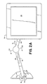
- proximal arm 10 The rotatable connections at the proximal and distal ends of proximal arm 10 are similar in structure and may be understood by reference to FIG. 2B which shows the connection between arms 10 and 20 in section.
- a vertical bearing post 25 attached to the distal end 12 of arm 10 is disposed within a bearing cavity 27 formed in the proximal end 22 of arm 20 thereby allowing arm 20 to rotate about bearing post 25.
- a second vertical bearing post 29 (FIG. 3) is attached to the proximal end 14 of arm 10 and is received within a bearing cavity (not shown) in clamp 16 which allows arm 10 to rotate about the central axis of bearing post 29.
- the articulated parallelogram structure integral to arm 10 used to cause distal end 12 of arm 10 to rise or fall in relation to proximal end 14 of arm 10.
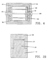
- the articulated parallelogram structure comprises a proximal member 30, a distal member 32, a top member 34, and a bottom member 36.
- Proximal member 30 is attached with screws to the proximal end 14 of arm 10 and distal member 32 is attached with screws to the distal end 12 of arm 10.
- Ends of top member 34 and bottom member 36 are pinned to proximal member 30 and distal member 32 by rivets 120, 122, 124 and 126 so as to form an articulated parallelogram structure.
- a sleeve 50 prevents twisting of arm 10 about an axis colinear with arm 10.
- Proximal member 30 is pinned by a rivet 128 to sleeve 50 at a location that is equidistant from the point of connection to top member 34 and bottom member 36 while distal member 32 is similarly pinned to sleeve 50 by rivet 130.
- the cross-section of proximal and distal members 30 and 32, taken at the point of connection to sleeve 50, is generally rectangular and is closely received within the rectangular cross-section of sleeve 50.
- Distal member 32 (not shown in FIG. 4) having a similar cross-section at its point of connection to sleeve 50 is also closely received within sleeve 50.
- Sleeve 50 thereby couples proximal member 30 and distal member 32 so as to resist torsional forces applied to arm 10.
- distal member 32 in relation to proximal member 30 is affected by changing the shape of the articulated parallelogram structure and the shape of the parallelogram structure is controlled by moving top member 34 in relation to bottom member 36.
- top member 34 and bottom member 36 are vertically aligned, as shown in FIG. 3, distal member 32 is at the same height as proximal member 30.
- distal member 32 rises in relation to proximal member 30.
- proximal member 30 and distal member 32 remain in substantially parallel relation independent of the shape of the parallelogram structure.
- a worm gearset 38 comprising a worm gear 40 and a worm 42, controls the relative position of top member 34 with respect to bottom member 36.
- a first pin 44 couples top member 34 to a first point near the outer periphery of gear 40, while a second pin 46 couples bottom member 36 to a second point near the outer periphery diametrically opposite the first point, worm 40 thereby acting as a constraint link.
- Pin 44 should be aligned with rivets 120 and 122, and pin 46 should be aligned with rivets 124 and 126.
- top member 34 moves in relation to bottom member 36, thereby affecting the shape of the parallelogram structure.
- worm gear 40 Counterclockwise rotation of worm gear 40 causes top member 34 to move to the left, thereby raising distal member 32. Subsequent clockwise rotation of worm gear 40 causes top member 34 to move to the right, thereby lowering distal member 32.
- Worm 42 is rotatably mounted through sleeve 50 and through slots in top and bottom members 34 and 36, which slots allow members 34 and 36 to move along an axis perpendicular to worm 42 without contacting worm 42. As worm gear 40 is rotated, its center remains stationary with respect to sleeve 50 and worm 42, worm 42 being held against worm gear 40 by sleeve 50.
- Worm 42 has an upper end 132 including a handle 48 which allows an operator to rotate worm gear 40.
- the operator can change the vertical position of terminal 22 simply by turning handle 48 which operation requires little effort. Adjustment of the vertical position of terminal 22 entails little risk of damage to equipment since worm gearset 38 is, by its nature, a self-locking mechanism. While worm 42 can rotate gear 40 with great mechanical advantage, gear 40 cannot rotate worm 42 because of friction and gear angles employed in gearset 38. Thus, the shape of the parallelogram structure, and the height of platform 26, is maintained against collapse by the self-locking gearset 38.
- platform 26 may be rotated about both vertical and horizontal axes. Rotation about the vertical axis allows platform 26 to orientate the screen of terminal 28 in any horizontal direction independent of the motion of distal arm 20, while rotation about the horizontal axis allows platform 26 to tilt the screen of terminal 28 to a desired angle vertically.
- a sleeve 80 having a first end 82 and a second end 84, is affixed to the underside of platform 26 along the desired horizontal axis of rotation.
- a first bushing 86 is placed at the first end 82 of sleeve 80, and a second bushing 88 is similarly placed at the second end 84 of sleeve 80, bushing 86 having a central bore 90 and bushing 88 having a central bore 92.
- a vertical bearing post 93 disposed within a bearing cavity 95 formed in the distal end 24 of distal arm 20, provides the vertical axis of rotation.
- a channel-shaped bracket 94 is affixed to bearing post 93, bracket 94 having a first channel leg 96 and a second channel leg 98.
- Bracket 94 is dimensioned to allow an inner surface of channel leg 96 to abut bushing 86 and an inner surface of channel leg 98 to abut bushing 88 when sleeve 80 is located within the channel of bracket 94.
- Channel leg 96 has a bore 100 aligned with central bore 90 of bushing 86
- channel leg 98 has a bore 102 aligned with central bore 92 of bushing 88.
- a threaded rod 104 extending through the length of sleeve 80 within central bores 90 and 92 and within bores 100 and 102, is thereby centered within sleeve 80.
- a first washer 106 placed on threaded rod 104 abuts an outer surface of channel leg 96, while a second washer 108 placed at the opposite end of threaded rod 104 abuts an outer surface of channel leg 98.
- a knob 110 attached to one end of threaded rod 104 abuts washer 106, and a similar knob 112 attached to the other end of threaded rod 104 abuts washer 108.
- Adjustment of knobs 110 and 112 on threaded rod 104 increases or decreases the friction between abutting elements in the assembly.
- platform 26 When the friction is high, platform 26 is fixed in relation to bracket 94, but when the friction is decreased, platform 26 may be rotated about threaded rod 104.
- the amount of friction determines how much force is required to rotate platform 26 about threaded rod 104.
- the friction is small enough to allow the user to tilt platform 26 yet great enough to maintain platform 26 in position without tightening the knobs.
- pegs 114 To prevent excessive rotation of platform 26 about threaded rod 104, pegs 114, connected to channel leg 96, extend into grooves 116 formed in the underside of platform 26, grooves 116 being aligned along a line perpendicular to threaded rod 104. As platform 26 is rotated in a first direction about threaded rod 104, pegs 114 move along the length of grooves 116 and contact a first end of grooves 116, whereupon further rotation of platform 26 is inhibited. Similarly, as platform 26 is rotated in the opposite direction, pegs 114 encounter the opposite end of grooves 116, and further rotation in that direction is checked. In a preferred embodiment, pegs 114 and grooves 116 allow platform 26 to rotate within a 30 degree range, 15 degrees in either direction from a horizontal position.
- Terminal 28 may be rotated and tilted without moving arm 10 or arm 20, allowing the screen of terminal 28 to be oriented in a variety of convenient directions. Vertical adjustment is accomplished by turning handle 48 in an appropriate direction to either raise or lower platform 26. Terminal 28 may be flexibly positioned to accommodate a particular user's posture or to allow several users to access terminal 28. Very little user effort is required to move terminal 28, and there is no risk of damage because the user does not have to lift the entire apparatus to change its vertical position.
Landscapes
- Engineering & Computer Science (AREA)
- General Engineering & Computer Science (AREA)
- Mechanical Engineering (AREA)
- Pivots And Pivotal Connections (AREA)
- Devices For Indicating Variable Information By Combining Individual Elements (AREA)
Claims (17)
- Support réglable comprenant :- un premier mécanisme de pivotement (14, 16) définissant un premier axe de rotation;- un second mécanisme de pivotement (22, 12) définissant un second axe de rotation parallèle au premier axe de rotation;- une structure polygonale raccordant le premier mécanisme de pivotement (14, 16) au second mécanisme de pivotement (22, 12), ladite structure polygonale comprenant une pièce proximale (30), une pièce distale (32), une pièce supérieure (34) et une pièce inférieure (36);- des moyens d'accouplement (120, 122, 124, 126) de la pièce proximale (30), de la pièce distale (32), de la pièce supérieure (34) et de la pièce inférieure (36) pour former une structure de parallélogramme articulé et- une liaison de contrainte possédant des première et seconde extrémités, la première extrémité étant couplée pivotante à la pièce supérieure (34) et la seconde extrémité étant couplée pivotante à la pièce inférieure (36),
support caractérisé par un moyen de couple pour appliquer un couple à la liaison de contrainte selon un axe perpendiculaire au plan constitué par ladite structure de parallélogramme, la liaison de contrainte comprenant un pignon de vis sans fin (40) et le moyen de couple comprenant une vis sans fin (42) engrènant avec le pignon de vis sans fin (40). - Support réglable selon la revendication 1, dans lequel la vis sans fin (42) possède une pièce d'actionnement (48) fixée sur elle.
- Support réglable selon la revendication 1 ou 2, dans lequel la pièce proximale (30) est raccordée au premier mécanisme de pivotement (14, 16) et la pièce distale (32) est raccordée au second mécanisme de pivotement (22, 12).
- Support réglable selon au moins l'une des revendications 1 à 3, comprenant, de plus, un manchon (50) dans lequel est placée la structure de parallélogramme articulé.
- Support réglable selon la revendication 4, dans lequel la pièce proximale (30) et la pièce distale (32) sont chacune raccordées à pivotement au manchon (50) en un endroit équidistant de la pièce supérieure (34) et de la pièce inférieure (36).
- Support réglable selon au moins l'une des revendications 4 ou 5, dans lequel la vis sans fin (42) est maintenue contre le pignon de vis sans fin (40) par le manchon (50).
- Support réglable selon au moins l'une des revendications 4 à 6, dans lequel la pièce distale (32) et la pièce proximale (30) sont rivetées en rotation sur le manchon (50).
- Support réglable selon au moins l'une des revendications 1 à 7, dans lequel la structure de parallélogramme maintient une relation constante entre les premier et second axes de rotation, autorisant un déplacement du second mécanisme de pivotement (22, 12) par rapport au premier mécanisme de pivotement (14, 16) dans une direction dont une composante est parallèle au premier axe de rotation tout en maintenant pratiquement constante la distance entre les premier et second mécanismes de pivotement (14, 16; 22, 12).
- Support réglable selon au moins l'une des revendications 1 à 8, comprenant, de plus, un moyen de fixation accouplant le premier mécanisme de pivotement (14, 16) à une surface de travail (18) de telle façon que le premier axe de rotation soit fixe par rapport à la surface de travail (18).
- Support réglable selon la revendication 9, dans lequel le moyen de fixation comprend :- une base (14) accouplée au premier mécanisme de pivotement (14, 16) et- un moyen d'accrochage (16) pour fixer la base (14) sur la surface de travail (18).
- Support réglable selon au moins l'une des revendications 1 à 10, comprenant, de plus, un moyen de support couplé au second mécanisme de pivotement (22, 12).
- Support réglable selon la revendication 11, dans lequel le moyen de support ne peut se déplacer par rapport au second mécanisme de pivotement (22, 12) dans une direction dont une composante est parallèle au premier axe de rotation.
- Support réglable selon au moins l'une des revendications 11 et 12, dans lequel ledit moyen de support comprend :- un bras (20) possédant des première et seconde extrémités, la première extrémité étant raccordée au second mécanisme de pivotement (22, 12) et- une plate-forme (26) couplée à la seconde extrémité du bras (20).
- Support réglable selon au moins l'une des revendications 11 à 13, dans lequel ledit moyen de support comprend :- un manchon (80) raccordé à ladite plate-forme (26);- des moyens de gousset (94, 96, 98) recevant ledit manchon (80), ledit manchon (80) possédant une première et une seconde extrémités (82, 84) logées dans ceux-ci;- un moyen de frottement assurant un frottement réglable entre lesdits moyens de gousset (94, 96, 98) et ledit manchon (80) et- un moyen de limitation définissant un intervalle de déplacement dudit manchon (80) par rapport auxdits moyens de gousset (94, 96, 98).
- Support réglable selon la revendication 14, dans lequel ledit moyen de limitation comprend :- une gorge (116) formée dans ladite plate-forme (26) et- un doigt (114) raccordé auxdits moyens de gousset (94, 96, 98), ledit doigt (114) s'étendant dans ladite gorge (116).
- Support réglable selon la revendication 15, dans lequel ladite gorge (116) possède des première et seconde extrémités et ledit intervalle de déplacement dudit manchon (80) est lié en un point où ledit doigt (114) entre en contact avec ladite première extrémité de ladite gorge (116) et en un point où ledit doigt (114) entre en contact avec ladite seconde extrémité de ladite gorge (116).
- Support réglable selon au moins l'une des revendications 14 à 16, dans lequel ledit moyen de support comprend, de plus, une tige (104) possédant des première et seconde extrémités autour desquelles tourne ledit manchon (80) et dans lequel ledit moyen de frottement comprend des boutons (110, 112) vissés sur les extrémités de ladite tige (104).
Applications Claiming Priority (2)
| Application Number | Priority Date | Filing Date | Title |
|---|---|---|---|
| US39183 | 1987-04-16 | ||
| US07/039,183 US4783036A (en) | 1987-04-16 | 1987-04-16 | Adjustable support |
Publications (3)
| Publication Number | Publication Date |
|---|---|
| EP0286959A2 EP0286959A2 (fr) | 1988-10-19 |
| EP0286959A3 EP0286959A3 (en) | 1990-03-28 |
| EP0286959B1 true EP0286959B1 (fr) | 1992-08-12 |
Family
ID=21904106
Family Applications (1)
| Application Number | Title | Priority Date | Filing Date |
|---|---|---|---|
| EP88105457A Expired - Lifetime EP0286959B1 (fr) | 1987-04-16 | 1988-04-06 | Support réglable |
Country Status (4)
| Country | Link |
|---|---|
| US (1) | US4783036A (fr) |
| EP (1) | EP0286959B1 (fr) |
| JP (1) | JPS63280292A (fr) |
| DE (1) | DE3873586T2 (fr) |
Families Citing this family (74)
| Publication number | Priority date | Publication date | Assignee | Title |
|---|---|---|---|---|
| US5299338A (en) * | 1988-01-15 | 1994-04-05 | Hill-Rom Company, Inc. | Hospital bed with pivoting headboard |
| US5072906A (en) * | 1988-01-15 | 1991-12-17 | Hill-Rom Company, Inc. | Hospital bed with pivoting headboard |
| USD325482S (en) | 1988-07-29 | 1992-04-21 | Schwartz C Bruce | Angioscopic support stand |
| JPH079185Y2 (ja) * | 1989-12-11 | 1995-03-06 | アルパイン株式会社 | 車載用ディスプレイ装置 |
| EP0445331A1 (fr) * | 1990-03-07 | 1991-09-11 | First National Investments Ltd. | Bras articulé pour support, en particulier pour support de console de visualisation |
| USD332628S (en) | 1990-04-07 | 1993-01-19 | Hans Friedrich Hefendehl | Surface-mountable holder for a plurality of desk trays |
| USD339703S (en) | 1990-05-23 | 1993-09-28 | Weber-Knapp Company | Keyboard support |
| USD325868S (en) | 1990-08-06 | 1992-05-05 | Rubbermaid Incorporated | Computer monitor support arm |
| USD342173S (en) | 1991-01-28 | 1993-12-14 | Ernst Stadelmann Gesellschaft M.B.H. | Swivel arm support for office equipment |
| US5186337A (en) * | 1991-08-09 | 1993-02-16 | Hill-Rom Company, Inc. | Pivoted power column |
| USD353159S (en) | 1992-03-09 | 1994-12-06 | Balthasar Kirchner | Surface-mountable paper tray |
| USD351860S (en) | 1992-03-09 | 1994-10-25 | Balthasar Kirchner | Surface-mountable plural paper tray unit |
| US5211362A (en) * | 1992-03-13 | 1993-05-18 | Householder Fred A | Adjustable quilting hoop stand |
| US5374019A (en) * | 1992-10-05 | 1994-12-20 | Fischer; Terry D. | Multi-positionable, collapsible tool bench |
| USD353066S (en) | 1993-06-22 | 1994-12-06 | Brandenberg Carl B | Equipment stand |
| USD365462S (en) | 1993-09-15 | 1995-12-26 | Brandenberg Carl B | Drafting table |
| US5746334A (en) * | 1993-11-24 | 1998-05-05 | Brandenberg; Carl Brock | Apparatus for supporting modular and cooperating components |
| GB2294874B (en) * | 1994-11-10 | 1999-04-07 | Grorud Eng Ltd | Height adjustable support |
| IT241826Y1 (it) * | 1996-03-14 | 2001-05-17 | Mediwork Srl | Struttura di supporto perfezionata particolarmente per visori,microscopi, monitor, televisori o simili |
| USD383621S (en) * | 1996-04-05 | 1997-09-16 | Haworth, Inc. | Monitor support |
| DE29616976U1 (de) * | 1996-09-28 | 1996-12-19 | H.-J. Bernstein GmbH Unternehmensbereich Gehäusetechnik, 32479 Hille | Tragarm |
| US6644748B2 (en) * | 1999-02-25 | 2003-11-11 | Health Postures, Inc. | Synergistic body positioning and dynamic support system |
| US6409134B1 (en) * | 1999-06-07 | 2002-06-25 | Innovative Office Products, Inc. | Arm apparatus for mounting electronic devices with cable management system |
| JP4713744B2 (ja) * | 1999-05-10 | 2011-06-29 | イノヴェイティヴ・オフィス・プロダクツ,インコーポレイテッド | 電子装置取着アーム装置 |
| US6478274B1 (en) * | 1999-05-10 | 2002-11-12 | Innovative Office Products, Inc. | Arm apparatus for mounting electronic devices |
| FI991147A7 (fi) * | 1999-05-20 | 2000-11-21 | Nokia Corp | Näyttölaitteisto |
| US6419511B2 (en) | 1999-06-01 | 2002-07-16 | Christopher A. Lizell | Modular support system |
| JP4489210B2 (ja) * | 1999-06-03 | 2010-06-23 | 株式会社岡村製作所 | ディスプレイ支持装置 |
| US6609691B2 (en) * | 1999-06-07 | 2003-08-26 | Innovative Office Products, Inc. | Arm apparatus for mounting electronic devices with cable management system |
| GB2360894B (en) * | 2000-03-30 | 2004-11-10 | Peter Thomas Bosson | Display device support system |
| US6491268B1 (en) * | 2000-10-09 | 2002-12-10 | Steelcase Development Corporation | Platform assembly for supporting portable computers and the like |
| EP1421458B1 (fr) | 2001-08-03 | 2010-04-07 | Hill-Rom Services, Inc. | Systeme informatique sur lieu de traitement d'un patient |
| US6851226B2 (en) | 2002-02-15 | 2005-02-08 | Steelcase Development Corporation | Partition panel with modular appliance mounting arrangement |
| US6684929B2 (en) | 2002-02-15 | 2004-02-03 | Steelcase Development Corporation | Panel system |
| US6712321B1 (en) * | 2003-05-21 | 2004-03-30 | Compal Electronics, Inc. | Adjustable supporting device for a display panel |
| US7380760B2 (en) * | 2003-05-30 | 2008-06-03 | Csav, Inc. | Self-balancing adjustable mounting system with friction adjustment |
| US7296774B2 (en) | 2004-01-02 | 2007-11-20 | Clo Systems, Llc | Viewing angle adjustment system for a monitor |
| US7677515B2 (en) * | 2004-07-07 | 2010-03-16 | Innovative Office Products, Inc. | Arm apparatus with reinforcement |
| US7415790B1 (en) * | 2004-08-27 | 2008-08-26 | Andrew S. Ruhland | Slidable swing arm mount for weapon |
| WO2006132938A2 (fr) | 2005-06-03 | 2006-12-14 | Steel Case Development Corporation | Assemblage de bras de support |
| US8089750B2 (en) * | 2005-10-18 | 2012-01-03 | Computer Ergotech, Llc | Multi-sectioned arms for portable electronic devices |
| CN100414372C (zh) * | 2005-11-04 | 2008-08-27 | 群康科技(深圳)有限公司 | 液晶显示装置 |
| USD539293S1 (en) * | 2005-12-13 | 2007-03-27 | May Gordon G | Adjustable support arm for video monitor |
| USD555657S1 (en) * | 2006-01-30 | 2007-11-20 | Casey Loyd | Monitor support arm |
| US7922137B2 (en) * | 2006-08-04 | 2011-04-12 | Innovative Office Products, Inc. | Laptop holder for extension arm |
| US7461825B2 (en) * | 2006-09-18 | 2008-12-09 | Alcon, Inc. | Tray support arm assembly |
| US20080078397A1 (en) * | 2006-09-28 | 2008-04-03 | Ronald Scott | Hose support system |
| US20100201165A1 (en) * | 2007-04-24 | 2010-08-12 | James Dankovich | Ergonomic work station |
| EP2142041A4 (fr) * | 2007-04-24 | 2013-01-16 | James Dankovich | Station de travail mobile autonome intégrée |
| USD651812S1 (en) * | 2009-09-30 | 2012-01-10 | Samsung Electronics Co., Ltd. | Digital photo frame |
| EP2374439A3 (fr) | 2010-04-09 | 2015-11-25 | Hill-Rom Services, Inc. | Support de patient, communication et appareil de calcul |
| US9074721B2 (en) | 2010-06-09 | 2015-07-07 | Alex Lau | Support system |
| US9316346B2 (en) | 2010-06-09 | 2016-04-19 | Colebrook Bosson Saunders (Products) Limited | Support system |
| JP5918232B2 (ja) * | 2010-07-08 | 2016-05-18 | サウスコ,インコーポレイティド | ディスプレイ支持装置 |
| USD684982S1 (en) | 2010-08-11 | 2013-06-25 | Colebrook Bosson Saunders (Products) Limited | Display support with indicator window |
| USD662101S1 (en) * | 2010-11-19 | 2012-06-19 | Synexxus, Inc. | Movable mounting arm |
| US9355219B2 (en) * | 2011-05-02 | 2016-05-31 | Omnicell, Inc. | Dispensing cabinet with articulating arm |
| US11304528B2 (en) | 2012-09-20 | 2022-04-19 | Steelcase Inc. | Chair assembly with upholstery covering |
| USD697726S1 (en) | 2012-09-20 | 2014-01-21 | Steelcase Inc. | Chair |
| US9706845B2 (en) | 2012-09-20 | 2017-07-18 | Steelcase Inc. | Chair assembly |
| US8757044B2 (en) | 2012-10-25 | 2014-06-24 | H & H Tool Shop, Llc | Weapon mounting system for firearms |
| US8757043B2 (en) | 2012-10-25 | 2014-06-24 | H & H Tool Shop, Llc | Weapon mounting system for firearms |
| US9539155B2 (en) | 2012-10-26 | 2017-01-10 | Hill-Rom Services, Inc. | Control system for patient support apparatus |
| US10474808B2 (en) | 2013-03-29 | 2019-11-12 | Hill-Rom Services, Inc. | Hospital bed compatibility with third party application software |
| US8955905B2 (en) * | 2013-06-07 | 2015-02-17 | Neutral Posture, Inc. | Seating assembly having a seat-mounted attachment assembly for adjustable extension arm |
| USD743969S1 (en) | 2013-10-16 | 2015-11-24 | Wirepath Home Systems, Llc | Single arm articulating mount for an electronic display |
| USD747724S1 (en) | 2013-12-20 | 2016-01-19 | Wirepath Home Systems, Llc | Dual arm articulating mount for an electronic display |
| US9516945B2 (en) | 2015-01-22 | 2016-12-13 | Haworth, Inc. | Modular worksurface system |
| US20180080598A1 (en) * | 2016-09-20 | 2018-03-22 | Apple Inc. | Counterbalanced display stand |
| CN107917314A (zh) * | 2017-10-18 | 2018-04-17 | 陈彬 | 一种新型计算机显示器固定装置及其工作方法 |
| CN108644552B (zh) * | 2018-05-07 | 2021-04-09 | 南京溧水高新创业投资管理有限公司 | 一种家用壁挂式显示器安装架 |
| CN112327013B (zh) * | 2020-10-31 | 2022-09-09 | 贵州电网有限责任公司 | 一种容性设备带电测试辅助工具 |
| CN114376364A (zh) * | 2022-01-18 | 2022-04-22 | 武狄实业(上海)有限公司 | 一种具有转动支架的电竞椅 |
| USD1076885S1 (en) | 2022-12-02 | 2025-05-27 | Sonos, Inc. | Wall mount for an audio device |
Family Cites Families (15)
| Publication number | Priority date | Publication date | Assignee | Title |
|---|---|---|---|---|
| US256583A (en) * | 1882-04-18 | Dental bracket | ||
| US3000606A (en) * | 1957-08-16 | 1961-09-19 | American Sterilizer Co | Balanced mounting means for a surgical lamp |
| GB879336A (en) * | 1958-05-27 | 1961-10-11 | Eversure Accessories Ltd | Improvements in driving mirrors for motor vehicles |
| US3160379A (en) * | 1963-10-29 | 1964-12-08 | S S White Dental Mfg Co | Tray support for a dental unit |
| FR1422927A (fr) * | 1964-10-27 | 1966-01-03 | Ritter Co | Plateau à instruments pour équipements de cabinets dentaires |
| US4183489A (en) * | 1978-11-20 | 1980-01-15 | Copher Joseph E | Adjustable bracket |
| US4397439A (en) * | 1981-02-13 | 1983-08-09 | Syntex (U.S.A.) Inc. | Brake assembly for dental tray support arm |
| US4542872A (en) * | 1983-02-09 | 1985-09-24 | Prime Computer, Inc. | Terminal with tilt-swivel display |
| DE3416823A1 (de) * | 1983-06-06 | 1984-12-06 | Friedhelm 8000 München Kreuzer | Stativ mit einem zur hoehenverstellung schenkbaren ausleger |
| US4589621A (en) * | 1984-01-03 | 1986-05-20 | International Business Machines Corporation | Ergonomic monitor stand |
| US4547027A (en) * | 1984-02-21 | 1985-10-15 | Itt Corporation | Modular swivel connector |
| US4562987A (en) * | 1984-05-14 | 1986-01-07 | Global Equipment Company | Computer terminal support with five degrees of freedom |
| DE3568255D1 (en) * | 1984-12-10 | 1989-03-23 | Siemens Ag | Parallelogram supporting arm with a counterbalancing mechanism |
| DE8530047U1 (de) * | 1985-10-23 | 1986-05-15 | Ncr Corp., Dayton, Ohio | Ausziehbarer, höhenverstellbarer Schwenkarm für Bildschirmgeräte od. dgl. |
| DE3600613A1 (de) * | 1986-01-11 | 1987-07-16 | Wella Ag | Einrichtung zum positionieren von informationsgeraeten |
-
1987
- 1987-04-16 US US07/039,183 patent/US4783036A/en not_active Expired - Fee Related
-
1988
- 1988-04-06 DE DE8888105457T patent/DE3873586T2/de not_active Expired - Fee Related
- 1988-04-06 EP EP88105457A patent/EP0286959B1/fr not_active Expired - Lifetime
- 1988-04-15 JP JP63093310A patent/JPS63280292A/ja active Pending
Also Published As
| Publication number | Publication date |
|---|---|
| US4783036A (en) | 1988-11-08 |
| EP0286959A2 (fr) | 1988-10-19 |
| DE3873586T2 (de) | 1993-03-25 |
| JPS63280292A (ja) | 1988-11-17 |
| EP0286959A3 (en) | 1990-03-28 |
| DE3873586D1 (de) | 1992-09-17 |
Similar Documents
| Publication | Publication Date | Title |
|---|---|---|
| US4783036A (en) | Adjustable support | |
| US4836486A (en) | Adjustable support | |
| CA1282451C (fr) | Poste de travail escamotable | |
| US4695024A (en) | Test system manipulator arm | |
| US5170975A (en) | Articulated arm with spring for counterbalancing | |
| US4768744A (en) | Apparatus for supporting a load in a dynamically balanced condition | |
| US4708312A (en) | Extensible height-adjustable swivel arm for supporting a display or the like | |
| US4747353A (en) | Straight line motion mechanism | |
| US4082244A (en) | Counterbalancing supporting device | |
| US4515087A (en) | Height adjustable table | |
| GB2222939A (en) | Adjustable CRT support stand | |
| US4840363A (en) | Telescoping, sterile upright support assembly | |
| US5340072A (en) | Linkage assembly for mechanical arm | |
| JPS6367078B2 (fr) | ||
| US4934647A (en) | Universal mount | |
| US20040099779A1 (en) | Keyboard support mechanism | |
| EP0365576A1 (fr) | Dispositif destine a soutenir la main. | |
| EP0816744A1 (fr) | Bras à équilibrage constant pour écran | |
| EP0636226A1 (fr) | Bras de support mobile | |
| JPH08328693A (ja) | 縦型ワークセンター | |
| US6322031B1 (en) | Keyboard support tray with releasable wedge lock | |
| US4807836A (en) | Vertical and pivotal adjusting apparatus for drafting tables | |
| US4770382A (en) | Stand for display terminals in particular | |
| US5213292A (en) | Tension adjusting mechanism for tool balancer | |
| EP0563361B1 (fr) | Berceau ameliore destine a un support de bras mobile |
Legal Events
| Date | Code | Title | Description |
|---|---|---|---|
| PUAI | Public reference made under article 153(3) epc to a published international application that has entered the european phase |
Free format text: ORIGINAL CODE: 0009012 |
|
| AK | Designated contracting states |
Kind code of ref document: A2 Designated state(s): DE FR GB |
|
| PUAL | Search report despatched |
Free format text: ORIGINAL CODE: 0009013 |
|
| AK | Designated contracting states |
Kind code of ref document: A3 Designated state(s): DE FR GB |
|
| 17P | Request for examination filed |
Effective date: 19900928 |
|
| 17Q | First examination report despatched |
Effective date: 19910614 |
|
| ITF | It: translation for a ep patent filed | ||
| GRAA | (expected) grant |
Free format text: ORIGINAL CODE: 0009210 |
|
| AK | Designated contracting states |
Kind code of ref document: B1 Designated state(s): DE FR GB |
|
| ET | Fr: translation filed | ||
| REF | Corresponds to: |
Ref document number: 3873586 Country of ref document: DE Date of ref document: 19920917 |
|
| PLBE | No opposition filed within time limit |
Free format text: ORIGINAL CODE: 0009261 |
|
| STAA | Information on the status of an ep patent application or granted ep patent |
Free format text: STATUS: NO OPPOSITION FILED WITHIN TIME LIMIT |
|
| 26N | No opposition filed | ||
| PGFP | Annual fee paid to national office [announced via postgrant information from national office to epo] |
Ref country code: GB Payment date: 19940321 Year of fee payment: 7 |
|
| PGFP | Annual fee paid to national office [announced via postgrant information from national office to epo] |
Ref country code: FR Payment date: 19940412 Year of fee payment: 7 |
|
| PGFP | Annual fee paid to national office [announced via postgrant information from national office to epo] |
Ref country code: DE Payment date: 19940427 Year of fee payment: 7 |
|
| PG25 | Lapsed in a contracting state [announced via postgrant information from national office to epo] |
Ref country code: GB Effective date: 19950406 |
|
| GBPC | Gb: european patent ceased through non-payment of renewal fee |
Effective date: 19950406 |
|
| PG25 | Lapsed in a contracting state [announced via postgrant information from national office to epo] |
Ref country code: FR Effective date: 19951229 |
|
| PG25 | Lapsed in a contracting state [announced via postgrant information from national office to epo] |
Ref country code: DE Effective date: 19960103 |
|
| REG | Reference to a national code |
Ref country code: FR Ref legal event code: ST |