EP0286980A1 - Transformateur de haute tension - Google Patents
Transformateur de haute tension Download PDFInfo
- Publication number
- EP0286980A1 EP0286980A1 EP88105566A EP88105566A EP0286980A1 EP 0286980 A1 EP0286980 A1 EP 0286980A1 EP 88105566 A EP88105566 A EP 88105566A EP 88105566 A EP88105566 A EP 88105566A EP 0286980 A1 EP0286980 A1 EP 0286980A1
- Authority
- EP
- European Patent Office
- Prior art keywords
- winding
- transformer
- secondary winding
- sections
- windings
- Prior art date
- Legal status (The legal status is an assumption and is not a legal conclusion. Google has not performed a legal analysis and makes no representation as to the accuracy of the status listed.)
- Withdrawn
Links
- 238000004804 winding Methods 0.000 claims abstract description 77
- 239000004020 conductor Substances 0.000 claims abstract description 14
- 229910052751 metal Inorganic materials 0.000 claims description 14
- 239000002184 metal Substances 0.000 claims description 14
- 229910052782 aluminium Inorganic materials 0.000 claims description 6
- XAGFODPZIPBFFR-UHFFFAOYSA-N aluminium Chemical compound [Al] XAGFODPZIPBFFR-UHFFFAOYSA-N 0.000 claims description 6
- 238000010276 construction Methods 0.000 abstract 1
- 239000010408 film Substances 0.000 description 9
- RYGMFSIKBFXOCR-UHFFFAOYSA-N Copper Chemical compound [Cu] RYGMFSIKBFXOCR-UHFFFAOYSA-N 0.000 description 7
- 244000045947 parasite Species 0.000 description 5
- 239000011104 metalized film Substances 0.000 description 4
- 230000008878 coupling Effects 0.000 description 3
- 238000010168 coupling process Methods 0.000 description 3
- 238000005859 coupling reaction Methods 0.000 description 3
- 238000009413 insulation Methods 0.000 description 2
- 239000000463 material Substances 0.000 description 2
- 239000003990 capacitor Substances 0.000 description 1
- 229910052802 copper Inorganic materials 0.000 description 1
- 239000010949 copper Substances 0.000 description 1
- 238000003780 insertion Methods 0.000 description 1
- 230000037431 insertion Effects 0.000 description 1
- 230000001788 irregular Effects 0.000 description 1
- 238000004519 manufacturing process Methods 0.000 description 1
- 238000000034 method Methods 0.000 description 1
- 238000012986 modification Methods 0.000 description 1
- 230000004048 modification Effects 0.000 description 1
- 238000005476 soldering Methods 0.000 description 1
Images
Classifications
-
- H—ELECTRICITY
- H01—ELECTRIC ELEMENTS
- H01F—MAGNETS; INDUCTANCES; TRANSFORMERS; SELECTION OF MATERIALS FOR THEIR MAGNETIC PROPERTIES
- H01F27/00—Details of transformers or inductances, in general
- H01F27/28—Coils; Windings; Conductive connections
- H01F27/2804—Printed windings
-
- H—ELECTRICITY
- H01—ELECTRIC ELEMENTS
- H01F—MAGNETS; INDUCTANCES; TRANSFORMERS; SELECTION OF MATERIALS FOR THEIR MAGNETIC PROPERTIES
- H01F19/00—Fixed transformers or mutual inductances of the signal type
-
- H—ELECTRICITY
- H01—ELECTRIC ELEMENTS
- H01F—MAGNETS; INDUCTANCES; TRANSFORMERS; SELECTION OF MATERIALS FOR THEIR MAGNETIC PROPERTIES
- H01F38/00—Adaptations of transformers or inductances for specific applications or functions
- H01F38/42—Flyback transformers
Definitions
- the present invention relates to an electric high-voltage transformer to be employed for example for the power supply to a cinescope or the like.
- the power supply of a television cinescope usually amploys a high-voltage transformer of the so-called "Fly-Back Transformer” (FBT) type.
- FBT Fly-Back Transformer
- an FBT transformer comprises at least a primary winding and a secondary winding made of insulated copper wire.
- the secondary winding comprises a plurality of winding sections interconnected through rectfyer means so as to form a voltage multiplyer making use also of the parasite capacities between the respective sections.
- the sections of the secondary winding are formed by a single winding operation to be coaxially disposed side by side along a common core.
- the secondary winding comprises a very great number (several thousands) of windings, and the current flowing therethrough is rather weak (on the order of 1 mA), so that it is preferable to employ a particularly thin copper wire in order to limit the overall dimensions of the transformer.
- the copper wire forming the secondary winding normally has a diameter of about 40 ⁇ m and is therefore rather fragile, so that the winding operation has to be done very cautiously.
- the small diameter of the copper wire renders an accurate positioning of the individual windings of the secondary practically impossible, so that the distribution of the parasite capacities between the individual windings of the various sections becomes disadvantageously irregular.
- the efficient coupling between the transformer and an associated cinescope requires the impedance of the secondary winding to be minimized.
- an FBT trans- former this is accomplished by tuning the transformer to a harmonic (normaly the ninth harmonic) of the deflection frequency of the cinescope, which may for instance be 15.625 Hz.
- the tuning of the transformer is carried out by varying the reciprocal coupling between the primary and secondary windings, for example by varying the number and the axial positions of the individual windings of the secondary winding. For the reasons set forth above, this operation is obviously indesirably difficult and laborious. It is also to be noted that the tuning of the transformer is influenced by the impedance of the yoke of the cinescope, so that the tuning has to be changed whenever there is a variation of the characteristics of the associated cinescope.
- DST Diode Split Transformer
- a DST transformer is described for example in GB Patent 1,090,995, and comprises a primary winding normally made of an aluminum sheet carried on an insulating strip, and a secondary winding comprising a plurality of sections made of insulated copper wire.
- the sections of the secondary winding are concentrically disposed one within the other and Wound on respective cylindrical cores, the end portion of one section being connected to the start portion of the next section through a rectifyer.
- the difference of potential between successive individual windings is substantially constant, so that the parasite capacity distributed between all windings of a section of the secondary winding and the adjacent winding of the next section is likewise uniform.
- This transformer does thus not require any particular tuning for coupling it to a cinescope.
- the copper wire of the secondary winding is particularly thin for reason of dimensions, as a result of which the winding operation is rather delicate, and the positioning of the individual windings is relatively imprecise with regard to their concentricity with respect to the axis of the core.
- the assembly of the DST transformer is rendered rather complicated and expensive by the necessity of forming each section of the secondary winding in a separate step before mounting the sections concentrically with one another.
- An object of the present invention is the provision of a high-voltage transformer combining the advantages of the conventional prior art solutions while minimizing their disadvantages.
- an object of the present invention is the provision of a high-voltage transformer capable of being manufactured in a simple and precise manner while presenting a particularly low impedance value.
- a further object of the invention is to provide a high-voltage transformer of the type defined above, which presents particularly compact dimensions.
- a high-voltage transformer comprising at least a primary winding and a secondary winding having several sections, the sections of the secondary winding being disposed about a substantially cylindrical support in coaxial spaced alignment with one another, and connected in series through rectifyer means.
- the transformer is primarily characterized in that the sections of the secondary winding comprise respective coils composed of at least one laminar conductor wound onto said support over an insulating film. The windings of each coil are aligned with corresponding windings of the other series-connected coils.
- the laminar conductor preferably comprises the metal layer on a metallized insulating film, this metal layer having a resistance value of no more than 0.52 ⁇ .
- the high-voltage transformer according to the invention is designed to operate at relatively high frequencies, for example at least 15.625 Hz, and adapted to be used in the power supply of a consumer, for instance a cinescope.
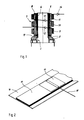
- the transformer essentially comprises an insulating support frame 3 having a substantially cylindrical portion 4 acting as the winding core of at least one primary winding 5 having terminals 6.
- Primary winding 5 is preferably formed by winding a metal strip, for instance aluminum, about core 4 onto an insulating film; this manufacturing technique is per se known and described for instance in EU-A-0,126,365, which relates to a SMT transformer, i.e. a transformer which finds its application in a field completely different from that of the transformer according to the invention, in which there are specific functional problems to be solved as will be described.
- EU-A-0,126,365 which relates to a SMT transformer, i.e. a transformer which finds its application in a field completely different from that of the transformer according to the invention, in which there are specific functional problems to be solved as will be described.
- Primary winding 5 is magnetically coupled to a secondary winding generally indicated at 7 and disposed about a substantially cylindrical insulating support 8 surrounding primary winding 5.
- Secondary winding 7 is composed of a plurality of winding sections coaxially disposed at spaced locations.
- Fig. 1 shows three such sections indicated at 9, 10 and 11.
- One terminal of section 9 is connected to a ground terminal 19, while its opposite terminal is connected to the adjacent terminal of section 10 through a rectifyer 12 or the like.
- the other terminal of section 10 is again connected to the adjacent terminal of section 11 through a rectifyer 13.
- the opposite terminal of section 11 is adapted to be connected to a cinescope (not shown) through a further rectifyer 14.
- the sections 9, 10 and 11 of the secondary winding are thus interconnected in series through respective rectifyers 12 and 13 in a per se known manner, to thereby form a voltage multiplyer by making use of the parasite capacities (not shown) forming between individual windings of the respective winding sections 9, 10 and 11 during operation at high frequencies.
- each section 9, 10, 11 of secondary winding 7 is formed as a separate coil made by winding at least one laminar conductor 15 overlying at least one insulating film 16 about support 8, film 16 being a plastic material or paper.
- laminar conductor 15 may be an aluminum strip of a width smaller than that of insulating film 16, so that the latter projects at opposite sides to thereby ensure proper electric insulation of the individual windings of the coil.
- coil sections 9, 10 and 11 preferably have the same number (several hundreds) of windings, and all windings of all sections are rpeferably coaxially aligned with one another. Each winding of each coil is thus aligned with the corresponding winding having the same circumferential dimension of the other series-connected coils.
- secondary winding 7 can be advantageously and readily formed by contemporaneously winding coils 9, 10 and 11 in a single winding operation.
- this winding operation offers no critical problems thanks to the mechanical strength of conductor 15 and insulating film 16 as compared to conventional solutions employing a thin wire as a conductor.
- the overall dimensions of the transformer can be noticeably reduced when conductor 15 is integrally formed with insulating film 16 in the form of a metallized film.
- conductor 15 is integrally formed with insulating film 16 in the form of a metallized film.
- the metal layer 15 of the metallized film employed for making secondary winding 7 is of a thickness selected to result in a particularly low resistance of no more than 0.5 ⁇ .
- metal layer 15 has a thickness of at least 0.1 ⁇ m; this value lies preferably between 0.1 and 2 ⁇ m, the overall thickness of the metallized film being about 3 to 10 ⁇ m.
- the highvoltage transformer according to the invention is of particularly compact dimensions, in addition to the advantages already explained. This results from the employ of a conductor 15 and insulating film 16 of a particularly small thickness, and irrespective thereof, of optimum mechanical strength, as already explained.
- the metal layer 15 having a resistance of no more that 0.51 ⁇ is not self-regenerating (contrary to what happens for example in many electric capacitors), so that a locakized short-circuit possibly occurring between windings adjacent metal strips 17 will not cause to an undesirable electric insulation.
- the electric connections and thhe number of coils 9, 10, 11, or the laminar conductor 15 may be of another material, for instance copper.
- primary winding 5 of the transformer may also be made in the conventional manner with the conductor in the form of a wire, or the coils 9, 10 and 11 may be made of respective laminar conductors of different width.
Landscapes
- Engineering & Computer Science (AREA)
- Power Engineering (AREA)
- Coils Or Transformers For Communication (AREA)
- Coils Of Transformers For General Uses (AREA)
Applications Claiming Priority (2)
| Application Number | Priority Date | Filing Date | Title |
|---|---|---|---|
| IT8745716A IT1210547B (it) | 1987-04-14 | 1987-04-14 | Trasformatore per alta tensione. |
| IT4571687 | 1987-04-14 |
Publications (1)
| Publication Number | Publication Date |
|---|---|
| EP0286980A1 true EP0286980A1 (fr) | 1988-10-19 |
Family
ID=11257607
Family Applications (1)
| Application Number | Title | Priority Date | Filing Date |
|---|---|---|---|
| EP88105566A Withdrawn EP0286980A1 (fr) | 1987-04-14 | 1988-04-07 | Transformateur de haute tension |
Country Status (3)
| Country | Link |
|---|---|
| EP (1) | EP0286980A1 (fr) |
| JP (1) | JPS63263708A (fr) |
| IT (1) | IT1210547B (fr) |
Cited By (2)
| Publication number | Priority date | Publication date | Assignee | Title |
|---|---|---|---|---|
| WO2003025957A1 (fr) * | 2001-09-19 | 2003-03-27 | Metal Manufactures Limited | Bobinage ameliore d'un transformateur |
| AU2002325092B2 (en) * | 2001-09-19 | 2007-11-29 | S C Power Systems, Inc. | Improved transformer winding |
Citations (2)
| Publication number | Priority date | Publication date | Assignee | Title |
|---|---|---|---|---|
| DE2930008A1 (de) * | 1979-07-24 | 1981-02-05 | Roederstein Kondensatoren | Transformator |
| EP0047497A1 (fr) * | 1980-09-10 | 1982-03-17 | Blaupunkt-Werke GmbH | Transformateur |
-
1987
- 1987-04-14 IT IT8745716A patent/IT1210547B/it active
-
1988
- 1988-04-07 EP EP88105566A patent/EP0286980A1/fr not_active Withdrawn
- 1988-04-13 JP JP63089187A patent/JPS63263708A/ja active Pending
Patent Citations (2)
| Publication number | Priority date | Publication date | Assignee | Title |
|---|---|---|---|---|
| DE2930008A1 (de) * | 1979-07-24 | 1981-02-05 | Roederstein Kondensatoren | Transformator |
| EP0047497A1 (fr) * | 1980-09-10 | 1982-03-17 | Blaupunkt-Werke GmbH | Transformateur |
Cited By (3)
| Publication number | Priority date | Publication date | Assignee | Title |
|---|---|---|---|---|
| WO2003025957A1 (fr) * | 2001-09-19 | 2003-03-27 | Metal Manufactures Limited | Bobinage ameliore d'un transformateur |
| US7233223B2 (en) | 2001-09-19 | 2007-06-19 | Metal Manufactures Limited | Transformer winding |
| AU2002325092B2 (en) * | 2001-09-19 | 2007-11-29 | S C Power Systems, Inc. | Improved transformer winding |
Also Published As
| Publication number | Publication date |
|---|---|
| JPS63263708A (ja) | 1988-10-31 |
| IT1210547B (it) | 1989-09-14 |
| IT8745716A0 (it) | 1987-04-14 |
Similar Documents
| Publication | Publication Date | Title |
|---|---|---|
| US5392020A (en) | Flexible transformer apparatus particularly adapted for high voltage operation | |
| US5559486A (en) | Bobbin for high frequency core | |
| US5719547A (en) | Transformer with bifilar winding | |
| US6342778B1 (en) | Low profile, surface mount magnetic devices | |
| US4704592A (en) | Chip inductor electronic component | |
| EP0222426B1 (fr) | Méthode de fabrication d'un transformateur à bobines coaxiales | |
| US6239683B1 (en) | Post-mountable planar magnetic device and method of manufacture thereof | |
| EP1547103A1 (fr) | Forme de bobinage | |
| US4922156A (en) | Integrated power capacitor and inductors/transformers utilizing insulated amorphous metal ribbon | |
| US3358256A (en) | Miniature low frequency transformer | |
| US4507640A (en) | High frequency transformer | |
| US4311978A (en) | U-Core pulse transformer | |
| JPH06112058A (ja) | 昇圧トランス | |
| US7023317B1 (en) | Cellular transformers | |
| US4812798A (en) | Electric transformer for microwave ovens | |
| US6160467A (en) | Transformer with center tap | |
| EP0286980A1 (fr) | Transformateur de haute tension | |
| JPH05283248A (ja) | 高周波昇圧トランス | |
| US4748430A (en) | Air-cooled high-frequency current transformer | |
| JPH05304033A (ja) | 高周波昇圧トランス | |
| US4092621A (en) | Thin foil pulse transformer coil for reducing distributed and leakage inductance | |
| US3004230A (en) | Electric inductor devices | |
| US4258467A (en) | Method of making transformer | |
| GB2099226A (en) | Ribbon wound transformer and method of making same | |
| EP0450448A1 (fr) | Transformateur plat |
Legal Events
| Date | Code | Title | Description |
|---|---|---|---|
| PUAI | Public reference made under article 153(3) epc to a published international application that has entered the european phase |
Free format text: ORIGINAL CODE: 0009012 |
|
| AK | Designated contracting states |
Kind code of ref document: A1 Designated state(s): BE CH DE ES FR GB IT LI LU NL SE |
|
| STAA | Information on the status of an ep patent application or granted ep patent |
Free format text: STATUS: THE APPLICATION IS DEEMED TO BE WITHDRAWN |
|
| 18D | Application deemed to be withdrawn |
Effective date: 19890420 |