EP0287094A2 - Dispositif de suspension arrière pour automobile - Google Patents
Dispositif de suspension arrière pour automobile Download PDFInfo
- Publication number
- EP0287094A2 EP0287094A2 EP88105971A EP88105971A EP0287094A2 EP 0287094 A2 EP0287094 A2 EP 0287094A2 EP 88105971 A EP88105971 A EP 88105971A EP 88105971 A EP88105971 A EP 88105971A EP 0287094 A2 EP0287094 A2 EP 0287094A2
- Authority
- EP
- European Patent Office
- Prior art keywords
- control arm
- wheel support
- suspension structure
- vehicle body
- rear suspension
- Prior art date
- Legal status (The legal status is an assumption and is not a legal conclusion. Google has not performed a legal analysis and makes no representation as to the accuracy of the status listed.)
- Granted
Links
- 239000000725 suspension Substances 0.000 title claims abstract description 44
- 241001247986 Calotropis procera Species 0.000 claims description 12
- 238000010276 construction Methods 0.000 abstract description 6
- 230000004048 modification Effects 0.000 description 6
- 238000012986 modification Methods 0.000 description 6
- 238000005452 bending Methods 0.000 description 2
- 238000010586 diagram Methods 0.000 description 2
Images



Classifications
-
- B—PERFORMING OPERATIONS; TRANSPORTING
- B60—VEHICLES IN GENERAL
- B60G—VEHICLE SUSPENSION ARRANGEMENTS
- B60G7/00—Pivoted suspension arms; Accessories thereof
-
- B—PERFORMING OPERATIONS; TRANSPORTING
- B60—VEHICLES IN GENERAL
- B60G—VEHICLE SUSPENSION ARRANGEMENTS
- B60G3/00—Resilient suspensions for a single wheel
- B60G3/18—Resilient suspensions for a single wheel with two or more pivoted arms, e.g. parallelogram
- B60G3/20—Resilient suspensions for a single wheel with two or more pivoted arms, e.g. parallelogram all arms being rigid
- B60G3/26—Means for maintaining substantially-constant wheel camber during suspension movement ; Means for controlling the variation of the wheel position during suspension movement
-
- B—PERFORMING OPERATIONS; TRANSPORTING
- B60—VEHICLES IN GENERAL
- B60G—VEHICLE SUSPENSION ARRANGEMENTS
- B60G2200/00—Indexing codes relating to suspension types
- B60G2200/40—Indexing codes relating to the wheels in the suspensions
- B60G2200/462—Toe-in/out
Definitions
- the present invention generally relates to an automobile rear structure, and more particularly, to a double wishbone type rear suspension structure for use in an automotive vehicle.
- Japanese Utility Model Laid-open Application (Jikkaisho) No. 58-167205 discloses a double wishbone type suspension as one of automobile suspensions, which is frequently utilized to pivotably support each wheel by way of a pair of upper and lower control arms.
- a damper unit pivotably coupled with the lower control arm is so disposed as to extend through a space formed in the upper control arm having a configuration generally in the form of a figure "A".
- the damper unit extends through the upper control arm, the damper unit is undesirably extremely lowered in service properties.
- the present invention has been developed with a view to substantially eliminating the above described disadvantage inherent in the prior art automobile rear suspension structure, and has for its essential object to provide an improved automobile double wishbone type rear suspension structure which can keep the design freedom therein and acts upon each rear wheel to be readily movable in a direction in which toe-in takes place.
- Another object of the present invention is to provide a rear suspension structure of the above described type which is simple in construction and can be readily manufactured at a low cost.
- an automobile rear suspension structure is provided with a knuckle arm or wheel support having one upper end portion and two lower end portions to pivotably support one of rear wheels, an H-shaped lower control arm having two outer end portions respectively pivotably connected with the two lower end portions of the wheel support and two front and rear inner end portions pivotably connected with a vehicle body, an A-shaped upper control arm having an outer end portion pivotably connected with the upper end portion of the wheel support and two front and rear inner end portions pivotably connected with the vehicle body, a damper unit pivotably connected at its upper end portion with the vehicle body to support the wheel support at a location below a connecting portion between the upper control arm and the wheel support.
- the damper unit is disposed at the back of the upper control arm in a direction longitudinally of the vehicle body.
- the offset relationship between the damper unit and the upper control arm in a direction longitudinally of a vehicle body can keep the design freedom for arranging the double wishbone type rear suspension in a limited space inside each rear wheel.
- the upper control arm is disposed in front of the damper unit, it is possible to obtain a relatively large inclination of an imaginary king pin axis which connects an outer rear end portion of the lower control arm and a connecting portion between the upper control arm and a wheel support. Consequently, the amount of offset from the center of each rear wheel becomes relatively large and this fact acts upon the rear wheels to be readily movable in a direction in which the toe-in takes place, when they are subjected to lateral force.
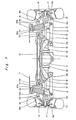
- an engine and mission unit 1 to be loaded on a front side of an automotive vehicle is securely mounted on a front cross member 3 in any known manner by way of a pair of engine mounts or engine supports 2 arranged widthwise of a vehicle body.
- a pair of control arms 4 are pivotably connected at their respective ends to opposite ends of the front cross member 3 whereas a pair of front wheels 6 are pivotably connected to the other respective ends of the control arms 4.
- the front wheels 6 are supported by a vehicle body 7 through a pair of respective damper units 5.
- the front cross member 3 is supported by the vehicle body 7 through a suitable elastic member (not shown) in any known manner.
- the engine and mission unit 1 is comprised of an engine as a driving source, a clutch and a mission.
- the engine and mission unit 1 is coupled with a differential unit 8 loaded on a rear side of the automotive vehicle by way of a driving shaft 9.
- the differential unit 8 is carried by a rear cross member 10 through a pair of elastic members 11 and is so constructed as to transmit driving force to rear wheels 13 by way of respective axle shafts 12.
- the rear cross member 10 is carried by the vehicle body 7 by a suitable elastic member (not shown) in any known manner and comprises a pair of juxtaposed first members 22 extending in a direction widthwise of the vehicle body, a pair of opposed second members 23 extending substantially vertically and each rigidly secured at its upper portion to one end of each first member 22, and a pair of third members 24 rigidly secured to lower portions of the second members 23 and to a lower surface of a central portion of each first member 22, as shown in Figs. 2 and 3.
- a suitable elastic member (not shown) in any known manner and comprises a pair of juxtaposed first members 22 extending in a direction widthwise of the vehicle body, a pair of opposed second members 23 extending substantially vertically and each rigidly secured at its upper portion to one end of each first member 22, and a pair of third members 24 rigidly secured to lower portions of the second members 23 and to a lower surface of a central portion of each first member 22, as shown in Figs. 2 and 3.
- the engine and mission unit 1 and the differential unit 8 are securely coupled with each other by a power plant frame 16 having a cross section generally in the form of a figure "U".
- the power plant frame 16 has one vertical side 16a and two opposed upper and lower horizontal sides 16b and 16c extending from opposite horizontal edges of its vertical side 16a so that an opening may be formed between the opposed horizontal sides 16b and 16c. Accordingly, the power plant frame 16 is relatively high in bending rigidity and flexible against torsion.
- a plurality of holes 25 having a suitable configuration are formed in the vertical side 16a of the power plant frame 16 and, each of the horizontal sides 16b and 16c thereof has an intermediate portion narrower than its opposite end portions. Consequently, the power plant frame 16 not only holds sufficient bending rigidity, but is improved in flexibility against the torsion, with its own weight being lightened.
- the power plant frame 16 is so mounted in the vehicle body as to encircle the majority of the driving shaft 9.
- An automotive vehicle accommodates two rear suspension units A for pivotably supporting respective rear wheels 13.
- Each rear suspension unit A is of the double wishbone type suspension comprising an H-shaped lower control arm 14, an A-shaped upper control arm 15, a shaft 17 pivotably connected at its opposite ends to opposed outer end portions 14a and 14c of the lower control arm 14 (that is, to two points in a direction longitudinally of the vehicle body), a knuckle arm or wheel support 18 having a lower end portion 18a pivotably connected with the shaft 17 and an upper end portion 18b pivotably connected with an outer end portion 15a of the upper control arm 15 by way of a bush 19, and a damper unit 20 pivotably connected at its lower end with the lower control arm 14.
- the upper control arm 15 is branched into two on its inner side, with the branched portion thereof being located inside the damper unit 20 in a direction widthwise of the vehicle body.
- the damper unit 20 is comprised of a damper 20a and a coil spring 20b.
- the connecting portion between the upper control arm 15 and the knuckle arm 18 is located in front of the center of rear wheels 13 in a direction longitudinally of the vehicle body, whereas the two connecting portions between the lower control arm 14 and the knuckle arm 18 are respectively located in front and in the rear of the center of rear wheels 13.
- the upper and lower control arms 15 and 14 are pivotably connected at their respective inner end portions 15b and 14b with upper and lower portions of the rear cross member 10, respectively.
- the damper unit 20 is located in the rear of the upper control arm 15 in a direction longitudinally of the vehicle body 7 and has an upper end portion supported by the vehicle body 7 in any known manner. In this way, since the upper control arm 15 and the damper unit 20 are spaced apart from each other or arranged in the offset relationship in a longitudinal direction of the vehicle body 7, the design freedom for arranging both the upper control arm 15 and the damper unit 20 can be assuredly kept within a limited space between the rear cross member 10 and each rear wheel 13, thus preventing the interference between the damper unit 20 and the axle shaft 12.
- a longer interval between mounting portions of the differential unit 8 suitable for mounting it on the vehicle body 7 is of advantage to the torsion or the like.
- This fact limits the space to be formed between each rear wheel 13 and the rear cross member 10 for mounting therein the rear suspension unit A. Accordingly, the offset relationship between the upper control arm 15 and the damper unit 20 in a direction longitudinally of the vehicle body 7 can advantageously be of service to the design freedom for the arrangement thereof.
- a rubber bush 21 and a pillow ball 26 respectively at front and rear connecting portions where the shaft 17 and two lower end portions 18a of the knuckle arm 18 are pivotably connected with each other.
- the pillow ball 26 of a member having a higher elasticity than the rubber bush 21 provided on the front side has.
- the pillow ball 26 may be replaced by other rubber bush having a spring constant larger than the rubber bush 21 has.
- the offset relationship between the damper unit 20 and the upper control arm 15 in a direction longitudinally of the vehicle body is of advantage to the design freedom for arranging the double wishbone type rear suspension A within a limited space.
- the pillow ball 26 disposed at the outer rear end portion 14c of the lower control arm 14 has a higher elasticity than the rubber bush 21 disposed on the outer front end portion 14a thereof has. This construction renders the elasticity of the front connecting portion 14a of the lower control arm 14 to be relatively lower than that of the rear connecting portion 14c thereof.
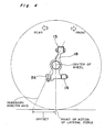
- the upper control arm 15 is arranged ahead of the damper unit 20 in a direction longitudinally of the vehicle body so that the inclination of an imaginary king pin axis is rendered to be larger, which axis is the one connecting the outer rear end portion 14c of the lower control arm 14 and the connecting portion 19 of the upper control arm 15 with the knuckle arm 18. Consequently, the amount of offset from the center of each rear wheel 13 becomes relatively large. That is to say, a length between a point where each rear wheel 13 gets in contact with the road surface and an intersection between the imaginary king pin axis and the road surface is rendered to be larger. Accordingly, the rear wheels 13 can readily move in a direction in which toe-in takes place, when lateral force acts thereupon.
- the knuckle arms 18 for supporting respective rear wheels 13 are caused to rotate so that the rear wheels 13 may be directed inside the vehicle body.
- This phenomenon is called "Toe-in” resulting in that the automotive vehicle is hard to spin, and therefore, the stability at the cornering can be advantageously improved.
- the lower control arm 14 has different spring constants at their two outer end portions 14a and 14c for connecting it with the lower ends 18a of the knuckle arm 18 for the increase of toe-in, it may have the same spring constant at its all end portions for connecting it with the upper and lower portions 18b and 18a of the knuckle arm 18.
- the arrangement of the upper control arm 15 in front of the damper unit 20 in a direction longitudinally of the vehicle body can provide a layout in which the toe-in can readily take place.
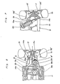
- Fig. 5 illustrates a modification of the present invention in which the lower control arm 14 ⁇ is rigidly secured at its outer rear end portion to another rubber bush 26 ⁇ which is pivotably coupled with the shaft 17.
- Fig. 6 indicates, in the case of Fig. 5, a relatively large offset between a point of action of the lateral force and the intersection between the imaginary king pin axis and the road surface.
- the damper unit 20 may be pivotably coupled at its lower end portion with the knuckle arm 18 ⁇ in place of the lower control arm 14, as shown in Fig. 7 which particularly shows another modification of the present invention.
- the present invention is applicable to the automobile rear suspension unit A equipped with an H-shaped lower control arm 14, an A-shaped upper control arm 15, a knuckle arm or wheel support 18 having longitudinally opposed lower end portions 18a pivotably connected with the outer end portions 14a and 14c of the lower control arm 14 and an upper end portion 18b pivotably connected with the upper control arm 15, and a damper unit 20 having a lower end pivotably connected with the lower control arm 14 and an upper end pivotably connected with the vehicle body.
- the inclination of imaginary king pin axis connecting the outer rear end portion 14c of the lower control arm 14 and the connecting portion between the upper control arm 15 and the wheel support 18 can be rendered to be relatively large so that the amount of offset from the center of each rear wheel 13 may be increased. Accordingly, the rear wheels 13 are advantageously effectively movable in a direction in which the toe-in takes place, when they are subjected to the lateral force.
- the offset arrangement between the damper unit 20 and the upper control arm 15 in a direction longitudinally of the vehicle body eliminates the necessity for extending the damper unit 20 through the upper control arm 15 and can be of service to the design freedom for arranging the double wishbone type rear suspension A within a limited space defined inside each rear wheel 13.
- Such an arrangement is also advantageous in that the damper unit 20 is remarkably improved in service properties.
Landscapes
- Engineering & Computer Science (AREA)
- Mechanical Engineering (AREA)
- Vehicle Body Suspensions (AREA)
- Body Structure For Vehicles (AREA)
Applications Claiming Priority (2)
| Application Number | Priority Date | Filing Date | Title |
|---|---|---|---|
| JP92642/87 | 1987-04-14 | ||
| JP62092642A JPH0780405B2 (ja) | 1987-04-14 | 1987-04-14 | 自動車のリヤサスペンシヨン構造 |
Publications (3)
| Publication Number | Publication Date |
|---|---|
| EP0287094A2 true EP0287094A2 (fr) | 1988-10-19 |
| EP0287094A3 EP0287094A3 (en) | 1989-08-23 |
| EP0287094B1 EP0287094B1 (fr) | 1993-03-10 |
Family
ID=14060105
Family Applications (1)
| Application Number | Title | Priority Date | Filing Date |
|---|---|---|---|
| EP88105971A Expired - Lifetime EP0287094B1 (fr) | 1987-04-14 | 1988-04-14 | Dispositif de suspension arrière pour automobile |
Country Status (5)
| Country | Link |
|---|---|
| US (1) | US4875705A (fr) |
| EP (1) | EP0287094B1 (fr) |
| JP (1) | JPH0780405B2 (fr) |
| KR (1) | KR910002275B1 (fr) |
| DE (1) | DE3878964T2 (fr) |
Cited By (2)
| Publication number | Priority date | Publication date | Assignee | Title |
|---|---|---|---|---|
| EP1738939A3 (fr) * | 2005-07-01 | 2008-05-21 | Audi Ag | Suspension à roue indépendante pour les roues arrières de véhicules à moteur |
| US20220247161A1 (en) * | 2021-02-01 | 2022-08-04 | Magna Powertrain Of America, Inc. | High voltage wire protection system for electric vehicles |
Families Citing this family (4)
| Publication number | Priority date | Publication date | Assignee | Title |
|---|---|---|---|---|
| US6000706A (en) * | 1996-05-14 | 1999-12-14 | Chrysler Corporation | Independent suspension for a vehicle axle with leading lower control arm geometry |
| FR2796594A1 (fr) * | 1999-07-23 | 2001-01-26 | Michelin & Cie | Vehicule automobile equipe d'un systeme de controle de l'angle de carrossage des roues du vehicule en virage |
| JP5111874B2 (ja) * | 2007-01-26 | 2013-01-09 | 本田技研工業株式会社 | クッション支持構造 |
| JP5049022B2 (ja) * | 2007-01-26 | 2012-10-17 | 本田技研工業株式会社 | サスペンションアーム構造 |
Family Cites Families (11)
| Publication number | Priority date | Publication date | Assignee | Title |
|---|---|---|---|---|
| US2190298A (en) * | 1936-08-26 | 1940-02-13 | Chrysler Corp | Wheel suspension |
| USRE24248E (en) * | 1952-11-04 | 1956-12-04 | hansen r | |
| US3422918A (en) | 1967-05-24 | 1969-01-21 | Gen Motors Corp | Independent rear wheel suspension |
| DE2035307A1 (de) * | 1970-07-16 | 1972-01-20 | Daimler Benz Ag, 7000 Stuttgart | Aufhangung des Radtragcrs eines nicht lenkbaren Rades |
| DE2038880A1 (de) * | 1970-08-05 | 1972-02-10 | Daimler Benz Ag | Radaufhaengung,insbesondere Hinterradaufhaengung an Kraftfahrzeugen |
| DE3048864C2 (de) * | 1980-12-23 | 1986-11-13 | Daimler-Benz Ag, 7000 Stuttgart | Achse, insbesondere Hinterachse für Personenkraftwagen, mit unabhängig von einander geführten Rädern |
| US4424845A (en) * | 1982-03-17 | 1984-01-10 | The Goodyear Tire & Rubber Company | Pneumatic tire tread |
| JPS58167205U (ja) * | 1982-05-06 | 1983-11-08 | トヨタ自動車株式会社 | サスペンシヨン装置に於ける連結構造 |
| JPS61263809A (ja) * | 1985-05-20 | 1986-11-21 | Nissan Motor Co Ltd | リヤサスペンシヨン |
| DE3681085D1 (de) * | 1985-07-03 | 1991-10-02 | Honda Motor Co Ltd | Radaufhaengung. |
| US4714270A (en) * | 1985-10-18 | 1987-12-22 | Ford Motor Company | Independent wheel suspension with toe correcting link |
-
1987
- 1987-04-14 JP JP62092642A patent/JPH0780405B2/ja not_active Expired - Fee Related
-
1988
- 1988-04-12 KR KR1019880004129A patent/KR910002275B1/ko not_active Expired
- 1988-04-14 US US07/181,422 patent/US4875705A/en not_active Expired - Lifetime
- 1988-04-14 EP EP88105971A patent/EP0287094B1/fr not_active Expired - Lifetime
- 1988-04-14 DE DE8888105971T patent/DE3878964T2/de not_active Expired - Fee Related
Cited By (3)
| Publication number | Priority date | Publication date | Assignee | Title |
|---|---|---|---|---|
| EP1738939A3 (fr) * | 2005-07-01 | 2008-05-21 | Audi Ag | Suspension à roue indépendante pour les roues arrières de véhicules à moteur |
| US20220247161A1 (en) * | 2021-02-01 | 2022-08-04 | Magna Powertrain Of America, Inc. | High voltage wire protection system for electric vehicles |
| US11848546B2 (en) * | 2021-02-01 | 2023-12-19 | Magna Powertrain Of America, Inc. | High voltage wire protection system for electric vehicles |
Also Published As
| Publication number | Publication date |
|---|---|
| KR910002275B1 (ko) | 1991-04-11 |
| DE3878964T2 (de) | 1993-09-02 |
| JPH0780405B2 (ja) | 1995-08-30 |
| US4875705A (en) | 1989-10-24 |
| KR880012382A (ko) | 1988-11-26 |
| DE3878964D1 (de) | 1993-04-15 |
| EP0287094B1 (fr) | 1993-03-10 |
| EP0287094A3 (en) | 1989-08-23 |
| JPS63258204A (ja) | 1988-10-25 |
Similar Documents
| Publication | Publication Date | Title |
|---|---|---|
| EP0675814B1 (fr) | Systeme de suspension pour les roues avant d'un vehicule | |
| US4826203A (en) | Automobile sub-frame structure | |
| US4848789A (en) | Vehicle chassis tranverse structural member | |
| US5566969A (en) | Rear axle suspension with reduced oversteer | |
| US5435591A (en) | Steerable front wheel suspension for vehicle | |
| US4589677A (en) | Suspension for a rigid axle for vehicles | |
| US5498020A (en) | Vehicle suspension system for a steerable drive wheel | |
| US5560638A (en) | Rear suspension system for vehicle | |
| US5380024A (en) | Double wishbone type suspension having A-type arm combined with pivoted expansible/contractible connection link and lateral link | |
| WO1995012499A1 (fr) | Systeme de suspension pour vehicule | |
| EP0301782B1 (fr) | Unité de suspension pour roue de véhicule | |
| US4986565A (en) | Wheel suspension system for vehicles | |
| US5511817A (en) | Vehicle axle suspension system | |
| US4982978A (en) | Rear suspension system | |
| JP2000025438A (ja) | 車両用サスペンション装置 | |
| EP0287094B1 (fr) | Dispositif de suspension arrière pour automobile | |
| US5362091A (en) | Rear suspension for vehicle | |
| JPH11170835A (ja) | トーションビーム式サスペンション | |
| US4519628A (en) | Vehicle suspensions | |
| EP1910108B1 (fr) | Suspension de roue individuelle | |
| KR100264603B1 (ko) | 자동차의 후륜 현가장치 | |
| EP0589273B1 (fr) | Train arrière à roues indépendantes pour véhicules automobiles | |
| JPH0585117A (ja) | 車輌用リヤサスペンシヨン | |
| KR100440113B1 (ko) | 자동차의 현가장치 | |
| JPH0224209A (ja) | リヤサスペンション装置 |
Legal Events
| Date | Code | Title | Description |
|---|---|---|---|
| PUAI | Public reference made under article 153(3) epc to a published international application that has entered the european phase |
Free format text: ORIGINAL CODE: 0009012 |
|
| AK | Designated contracting states |
Kind code of ref document: A2 Designated state(s): DE FR GB |
|
| PUAL | Search report despatched |
Free format text: ORIGINAL CODE: 0009013 |
|
| AK | Designated contracting states |
Kind code of ref document: A3 Designated state(s): DE FR GB |
|
| 17P | Request for examination filed |
Effective date: 19890904 |
|
| 17Q | First examination report despatched |
Effective date: 19910822 |
|
| GRAA | (expected) grant |
Free format text: ORIGINAL CODE: 0009210 |
|
| AK | Designated contracting states |
Kind code of ref document: B1 Designated state(s): DE FR GB |
|
| REF | Corresponds to: |
Ref document number: 3878964 Country of ref document: DE Date of ref document: 19930415 |
|
| ET | Fr: translation filed | ||
| PLBE | No opposition filed within time limit |
Free format text: ORIGINAL CODE: 0009261 |
|
| STAA | Information on the status of an ep patent application or granted ep patent |
Free format text: STATUS: NO OPPOSITION FILED WITHIN TIME LIMIT |
|
| 26N | No opposition filed | ||
| PGFP | Annual fee paid to national office [announced via postgrant information from national office to epo] |
Ref country code: FR Payment date: 20010409 Year of fee payment: 14 |
|
| PGFP | Annual fee paid to national office [announced via postgrant information from national office to epo] |
Ref country code: GB Payment date: 20010411 Year of fee payment: 14 |
|
| REG | Reference to a national code |
Ref country code: GB Ref legal event code: IF02 |
|
| PG25 | Lapsed in a contracting state [announced via postgrant information from national office to epo] |
Ref country code: GB Free format text: LAPSE BECAUSE OF NON-PAYMENT OF DUE FEES Effective date: 20020414 |
|
| GBPC | Gb: european patent ceased through non-payment of renewal fee |
Effective date: 20020414 |
|
| PG25 | Lapsed in a contracting state [announced via postgrant information from national office to epo] |
Ref country code: FR Free format text: LAPSE BECAUSE OF NON-PAYMENT OF DUE FEES Effective date: 20021231 |
|
| REG | Reference to a national code |
Ref country code: FR Ref legal event code: ST |
|
| PGFP | Annual fee paid to national office [announced via postgrant information from national office to epo] |
Ref country code: DE Payment date: 20060406 Year of fee payment: 19 |
|
| PG25 | Lapsed in a contracting state [announced via postgrant information from national office to epo] |
Ref country code: DE Free format text: LAPSE BECAUSE OF NON-PAYMENT OF DUE FEES Effective date: 20071101 |