EP0287171B1 - Transporteur - Google Patents
Transporteur Download PDFInfo
- Publication number
- EP0287171B1 EP0287171B1 EP88200693A EP88200693A EP0287171B1 EP 0287171 B1 EP0287171 B1 EP 0287171B1 EP 88200693 A EP88200693 A EP 88200693A EP 88200693 A EP88200693 A EP 88200693A EP 0287171 B1 EP0287171 B1 EP 0287171B1
- Authority
- EP
- European Patent Office
- Prior art keywords
- conveyor
- rotatable body
- conical
- longitudinal direction
- moved
- Prior art date
- Legal status (The legal status is an assumption and is not a legal conclusion. Google has not performed a legal analysis and makes no representation as to the accuracy of the status listed.)
- Expired - Lifetime
Links
- 238000011144 upstream manufacturing Methods 0.000 claims description 8
- 238000010276 construction Methods 0.000 description 2
- 230000002093 peripheral effect Effects 0.000 description 2
- 238000007792 addition Methods 0.000 description 1
- 230000002441 reversible effect Effects 0.000 description 1
- 230000007704 transition Effects 0.000 description 1
Images

Classifications
-
- B—PERFORMING OPERATIONS; TRANSPORTING
- B65—CONVEYING; PACKING; STORING; HANDLING THIN OR FILAMENTARY MATERIAL
- B65G—TRANSPORT OR STORAGE DEVICES, e.g. CONVEYORS FOR LOADING OR TIPPING, SHOP CONVEYOR SYSTEMS OR PNEUMATIC TUBE CONVEYORS
- B65G47/00—Article or material-handling devices associated with conveyors; Methods employing such devices
- B65G47/52—Devices for transferring articles or materials between conveyors i.e. discharging or feeding devices
- B65G47/53—Devices for transferring articles or materials between conveyors i.e. discharging or feeding devices between conveyors which cross one another
- B65G47/54—Devices for transferring articles or materials between conveyors i.e. discharging or feeding devices between conveyors which cross one another at least one of which is a roller-way
-
- B—PERFORMING OPERATIONS; TRANSPORTING
- B65—CONVEYING; PACKING; STORING; HANDLING THIN OR FILAMENTARY MATERIAL
- B65G—TRANSPORT OR STORAGE DEVICES, e.g. CONVEYORS FOR LOADING OR TIPPING, SHOP CONVEYOR SYSTEMS OR PNEUMATIC TUBE CONVEYORS
- B65G13/00—Roller-ways
- B65G13/08—Roller-ways of curved form; with branch-offs
- B65G13/10—Switching arrangements
Definitions
- the invention relates to a conveyor provided with one or more transport means for moving objects in the longitudinal direction of the conveyor and with a rotatable body provided with a smooth surface and having its axis of rotation extending substantially parallel to the longitudinal direction of the conveyor and being adjustable in a substantially vertical direction between an operative position wherein the rotatable body extends partly above the transport means and an inoperative position, whereby in the operative position, in the direction in which the objects are moved by the conveyor during operation, the upper boundary line of the superficies of the rotatable body slopes upwards so that an object can be moved transversely to the longitudinal direction of the conveyor by means of said rotatable body.
- FR-A-1.559.270 discloses such a conveyor having cylindrical rotatable bodies.
- the rotatable body is conical the apex angle of the conical superficies being located at the upstream end of the rotatable body.
- GB-A-1.143.159 shows a conveyor system comprising a plurality of conical rollers arranged in an arc between two intersecting straight line conveyor sections, said rollers comprising peripheral grooves through which parts of a conveyor section extend.
- the conical rollers are movable up and down between an operative and an inoperative position.
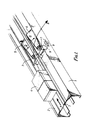
- Fig. 1 illustrates a part of a frame 1 of a conveyor.
- the conveyor is provided with a pair of endless belts 2 and 3 extending parallel to each other, which belts are driven by means of driving means (not shown), such that the upper parts of said belts 2 and 3 move over the upper side of the frame 1 in the direction according to arrow A.
- driving means not shown
- objects 4 present on the belts 2 and 3 can be moved by means of said belts, therefore, in the direction according to arrow A in the longitudinal direction of the conveyor.
- a pair of conical bodies 5 and 6 are provided for this purpose, which bodies are arranged such that the central axes of said conical bodies extend parallel to the longitudinal direction of the conveyor, seen in top view.
- the conical body 5 is thereby located between the two conveyor belts 2 and 3 in the path of the objects moved by the conveyor belts 2 and 3 in the direction according to arrow A, whilst the conical element 6 is arranged beside said path.
- Pulleys 7 are furthermore fitted to the upstream ends of the conical elements, which pulleys are coupled, by means of belts 8, to a horizontally extending roll 9, which is supported freely rotatably by the frame 1.
- the roll 9 thereby extends perpendicularly to the longitudinal direction of the belts 2 and 3 and during operation said roll will be set rotating by the lower parts of the belts 2 and/or 3 in the direction according to arrow C. It will be apparent that in that case the conical bodies 5 and 6 are set into rotation via the belts 8, in the direction according to arrow D.
- said body 6 can generally take a fixed position. If desired said conical body 6 may also be provided adjustably in vertical direction, however, as will be further described hereinafter for the conical body 5.
- the body 5 may be coupled, near its end supporting the pulley 7, to a support 10 fixed to the frame 1, such that the body 5 is pivotable, by means of means not shown, about a pivot axis 11 extending transversely to the longitudinal direction of the conveyor, as indicated by the double arrow E.
- the construction is such that in a first position, illustrated by means of dotted lines, the upper boundary lines of the superficies of the conical body 5 will be located under the upper surfaces of the transport means supporting the objects 4, in this case the upper surfaces of the conveyor belts 2 and 3.
- the objects 4 moved by the conveyor belts 2 and 3 can then pass the conical body 5 in the direction according to arrow A without impediment.
- the conical body 5 projects partly above the upper surfaces of the belts 2 and 3, however, whereby preferably care is taken that the uppermost point of the upstream end of the conical body is located at least substantially at the same level as the upper surface of the belts 2 and 3, whilst the upper boundary line of the conical body then extends gradually upwards from this point, as is apparent from fig 3.
- the conical body 5 may also be moved parallel to itself by means of adjusting means (not shown), in the direction according to arrow F, between the inactive position illustrated by dotted lines in fig 4, and the active position illustrated by full lines, instead of being pivoted between an inactive position illustrated by dotted lines and an active position illustrated by full lines.
Landscapes
- Engineering & Computer Science (AREA)
- Mechanical Engineering (AREA)
- Structure Of Belt Conveyors (AREA)
- Manufacturing And Processing Devices For Dough (AREA)
- Apparatus Associated With Microorganisms And Enzymes (AREA)
- Pharmaceuticals Containing Other Organic And Inorganic Compounds (AREA)
- Materials For Medical Uses (AREA)
- Branching, Merging, And Special Transfer Between Conveyors (AREA)
Claims (6)
Priority Applications (1)
| Application Number | Priority Date | Filing Date | Title |
|---|---|---|---|
| AT88200693T ATE68437T1 (de) | 1987-04-16 | 1988-04-12 | Foerderer. |
Applications Claiming Priority (2)
| Application Number | Priority Date | Filing Date | Title |
|---|---|---|---|
| NL8700901A NL8700901A (nl) | 1987-04-16 | 1987-04-16 | Transporteur. |
| NL8700901 | 1987-04-16 |
Publications (2)
| Publication Number | Publication Date |
|---|---|
| EP0287171A1 EP0287171A1 (fr) | 1988-10-19 |
| EP0287171B1 true EP0287171B1 (fr) | 1991-10-16 |
Family
ID=19849867
Family Applications (1)
| Application Number | Title | Priority Date | Filing Date |
|---|---|---|---|
| EP88200693A Expired - Lifetime EP0287171B1 (fr) | 1987-04-16 | 1988-04-12 | Transporteur |
Country Status (4)
| Country | Link |
|---|---|
| EP (1) | EP0287171B1 (fr) |
| AT (1) | ATE68437T1 (fr) |
| DE (1) | DE3865496D1 (fr) |
| NL (1) | NL8700901A (fr) |
Families Citing this family (9)
| Publication number | Priority date | Publication date | Assignee | Title |
|---|---|---|---|---|
| NL9200819A (nl) * | 1992-05-08 | 1993-12-01 | Vanderlande Ind Nederland | Transportinrichting. |
| IT1256148B (it) * | 1992-09-18 | 1995-11-29 | Alcatel Italia | Unita' modulare di smistamento per apparati trasportatori |
| US5979633A (en) * | 1997-04-25 | 1999-11-09 | United Parcel Service Of America Inc. | Conveyor having high speed discharge capabilities |
| US6076653A (en) * | 1997-04-29 | 2000-06-20 | United Parcel Service Of America, Inc. | High speed drum sorting conveyor system |
| US5967290A (en) * | 1997-08-13 | 1999-10-19 | United Parcel Service Of America | High speed bobbin-type sorter for parcels |
| US6182813B1 (en) | 1998-04-29 | 2001-02-06 | United Parcel Service Of America | Side conveyor disc including quick-change features |
| DE102006035050A1 (de) * | 2006-07-28 | 2008-01-31 | Siemens Ag | Verteileinrichtung für Stückgut |
| CN101148221B (zh) * | 2007-09-03 | 2010-09-08 | 浙江大学 | 带抽斗式托盘的输送装置 |
| FR3086933B1 (fr) * | 2018-10-05 | 2021-06-18 | Fives Syleps | Dispositif de transfert pour convoyeur |
Family Cites Families (3)
| Publication number | Priority date | Publication date | Assignee | Title |
|---|---|---|---|---|
| BE517911A (fr) * | 1953-02-19 | |||
| US3334723A (en) * | 1966-09-27 | 1967-08-08 | Cutler Hammer Inc | Transfer conveyor units and control systems therefor |
| US3456773A (en) * | 1967-03-07 | 1969-07-22 | American Chain & Cable Co | Case diverter |
-
1987
- 1987-04-16 NL NL8700901A patent/NL8700901A/nl not_active Application Discontinuation
-
1988
- 1988-04-12 DE DE8888200693T patent/DE3865496D1/de not_active Expired - Lifetime
- 1988-04-12 EP EP88200693A patent/EP0287171B1/fr not_active Expired - Lifetime
- 1988-04-12 AT AT88200693T patent/ATE68437T1/de not_active IP Right Cessation
Also Published As
| Publication number | Publication date |
|---|---|
| DE3865496D1 (en) | 1991-11-21 |
| EP0287171A1 (fr) | 1988-10-19 |
| ATE68437T1 (de) | 1991-11-15 |
| NL8700901A (nl) | 1988-11-16 |
Similar Documents
| Publication | Publication Date | Title |
|---|---|---|
| JPS6326041B2 (fr) | ||
| US4815580A (en) | Intermediate storage station | |
| US5775435A (en) | Apparatus for separating potatoes from other materials | |
| US4546870A (en) | Device for transporting and positioning dough triangles in crescent shaped dough rolls forming machines | |
| US5626219A (en) | Apparatus and method for stabilising material transported on conveyor belts | |
| WO1992006908A1 (fr) | Ameliorations des rouleaux inferieurs d'entrainement de bande transporteuse | |
| EP0287171A1 (fr) | Transporteur | |
| US5176243A (en) | Egg orienting apparatus | |
| US4958724A (en) | Tubular belt conveyor | |
| EP0417363B1 (fr) | Convoyeur vertical | |
| US4353458A (en) | Belt supports for accumulators | |
| US4241822A (en) | Apparatus for conveying rod-like articles | |
| NL8601621A (nl) | Transportinrichting. | |
| US4413723A (en) | Method and apparatus for conveying a sheet | |
| AU2019258174A1 (en) | Conveying and sorting apparatus | |
| EP0569073B1 (fr) | Convoyeur | |
| US4164280A (en) | Roller conveyor | |
| US3990685A (en) | Kneading apparatus for breadmaking | |
| CA1164898A (fr) | Transporteur | |
| US4572352A (en) | Apparatus for conveying rod-like articles | |
| JP3368762B2 (ja) | 仕分け設備 | |
| JP7627219B2 (ja) | コンベヤのための移送デバイス | |
| JPH0447151Y2 (fr) | ||
| JPH11193127A (ja) | タイル分別方法及び装置 | |
| EP0492732A1 (fr) | Convoyeur |
Legal Events
| Date | Code | Title | Description |
|---|---|---|---|
| PUAI | Public reference made under article 153(3) epc to a published international application that has entered the european phase |
Free format text: ORIGINAL CODE: 0009012 |
|
| AK | Designated contracting states |
Kind code of ref document: A1 Designated state(s): AT BE CH DE ES FR GB GR IT LI LU NL SE |
|
| 17P | Request for examination filed |
Effective date: 19890407 |
|
| 17Q | First examination report despatched |
Effective date: 19901005 |
|
| GRAA | (expected) grant |
Free format text: ORIGINAL CODE: 0009210 |
|
| ITF | It: translation for a ep patent filed | ||
| AK | Designated contracting states |
Kind code of ref document: B1 Designated state(s): AT BE CH DE ES FR GB GR IT LI LU NL SE |
|
| PG25 | Lapsed in a contracting state [announced via postgrant information from national office to epo] |
Ref country code: SE Effective date: 19911016 Ref country code: LI Effective date: 19911016 Ref country code: GR Free format text: LAPSE BECAUSE OF FAILURE TO SUBMIT A TRANSLATION OF THE DESCRIPTION OR TO PAY THE FEE WITHIN THE PRESCRIBED TIME-LIMIT Effective date: 19911016 Ref country code: ES Free format text: THE PATENT HAS BEEN ANNULLED BY A DECISION OF A NATIONAL AUTHORITY Effective date: 19911016 Ref country code: CH Effective date: 19911016 Ref country code: AT Effective date: 19911016 |
|
| REF | Corresponds to: |
Ref document number: 68437 Country of ref document: AT Date of ref document: 19911115 Kind code of ref document: T |
|
| REF | Corresponds to: |
Ref document number: 3865496 Country of ref document: DE Date of ref document: 19911121 |
|
| ET | Fr: translation filed | ||
| REG | Reference to a national code |
Ref country code: CH Ref legal event code: PL |
|
| PLBE | No opposition filed within time limit |
Free format text: ORIGINAL CODE: 0009261 |
|
| STAA | Information on the status of an ep patent application or granted ep patent |
Free format text: STATUS: NO OPPOSITION FILED WITHIN TIME LIMIT |
|
| 26N | No opposition filed | ||
| EPTA | Lu: last paid annual fee | ||
| NLT1 | Nl: modifications of names registered in virtue of documents presented to the patent office pursuant to art. 16 a, paragraph 1 |
Owner name: VANDERLANDE INDUSTRIES NEDERLAND B.V. |
|
| REG | Reference to a national code |
Ref country code: FR Ref legal event code: CD |
|
| REG | Reference to a national code |
Ref country code: GB Ref legal event code: IF02 |
|
| PGFP | Annual fee paid to national office [announced via postgrant information from national office to epo] |
Ref country code: FR Payment date: 20040226 Year of fee payment: 17 |
|
| PGFP | Annual fee paid to national office [announced via postgrant information from national office to epo] |
Ref country code: BE Payment date: 20040401 Year of fee payment: 17 |
|
| PGFP | Annual fee paid to national office [announced via postgrant information from national office to epo] |
Ref country code: GB Payment date: 20040407 Year of fee payment: 17 |
|
| PGFP | Annual fee paid to national office [announced via postgrant information from national office to epo] |
Ref country code: NL Payment date: 20040426 Year of fee payment: 17 |
|
| PGFP | Annual fee paid to national office [announced via postgrant information from national office to epo] |
Ref country code: LU Payment date: 20040429 Year of fee payment: 17 |
|
| PGFP | Annual fee paid to national office [announced via postgrant information from national office to epo] |
Ref country code: DE Payment date: 20040602 Year of fee payment: 17 |
|
| PG25 | Lapsed in a contracting state [announced via postgrant information from national office to epo] |
Ref country code: LU Free format text: LAPSE BECAUSE OF NON-PAYMENT OF DUE FEES Effective date: 20050412 Ref country code: IT Free format text: LAPSE BECAUSE OF NON-PAYMENT OF DUE FEES;WARNING: LAPSES OF ITALIAN PATENTS WITH EFFECTIVE DATE BEFORE 2007 MAY HAVE OCCURRED AT ANY TIME BEFORE 2007. THE CORRECT EFFECTIVE DATE MAY BE DIFFERENT FROM THE ONE RECORDED. Effective date: 20050412 Ref country code: GB Free format text: LAPSE BECAUSE OF NON-PAYMENT OF DUE FEES Effective date: 20050412 |
|
| PG25 | Lapsed in a contracting state [announced via postgrant information from national office to epo] |
Ref country code: BE Free format text: LAPSE BECAUSE OF NON-PAYMENT OF DUE FEES Effective date: 20050430 |
|
| BERE | Be: lapsed |
Owner name: *VANDERLANDE INDUSTRIES NEDERLAND B.V. Effective date: 20050430 |
|
| PG25 | Lapsed in a contracting state [announced via postgrant information from national office to epo] |
Ref country code: NL Free format text: LAPSE BECAUSE OF NON-PAYMENT OF DUE FEES Effective date: 20051101 Ref country code: DE Free format text: LAPSE BECAUSE OF NON-PAYMENT OF DUE FEES Effective date: 20051101 |
|
| GBPC | Gb: european patent ceased through non-payment of renewal fee |
Effective date: 20050412 |
|
| PG25 | Lapsed in a contracting state [announced via postgrant information from national office to epo] |
Ref country code: FR Free format text: LAPSE BECAUSE OF NON-PAYMENT OF DUE FEES Effective date: 20051230 |
|
| NLV4 | Nl: lapsed or anulled due to non-payment of the annual fee |
Effective date: 20051101 |
|
| REG | Reference to a national code |
Ref country code: FR Ref legal event code: ST Effective date: 20051230 |
|
| BERE | Be: lapsed |
Owner name: *VANDERLANDE INDUSTRIES NEDERLAND B.V. Effective date: 20050430 |