EP0287201A2 - Dosierapparat - Google Patents
Dosierapparat Download PDFInfo
- Publication number
- EP0287201A2 EP0287201A2 EP88301496A EP88301496A EP0287201A2 EP 0287201 A2 EP0287201 A2 EP 0287201A2 EP 88301496 A EP88301496 A EP 88301496A EP 88301496 A EP88301496 A EP 88301496A EP 0287201 A2 EP0287201 A2 EP 0287201A2
- Authority
- EP
- European Patent Office
- Prior art keywords
- motor
- wall
- dosing
- programmable
- control means
- Prior art date
- Legal status (The legal status is an assumption and is not a legal conclusion. Google has not performed a legal analysis and makes no representation as to the accuracy of the status listed.)
- Withdrawn
Links
Images
Classifications
-
- G—PHYSICS
- G01—MEASURING; TESTING
- G01F—MEASURING VOLUME, VOLUME FLOW, MASS FLOW OR LIQUID LEVEL; METERING BY VOLUME
- G01F11/00—Apparatus requiring external operation adapted at each repeated and identical operation to measure and separate a predetermined volume of fluid or fluent solid material from a supply or container, without regard to weight, and to deliver it
- G01F11/02—Apparatus requiring external operation adapted at each repeated and identical operation to measure and separate a predetermined volume of fluid or fluent solid material from a supply or container, without regard to weight, and to deliver it with measuring chambers which expand or contract during measurement
- G01F11/021—Apparatus requiring external operation adapted at each repeated and identical operation to measure and separate a predetermined volume of fluid or fluent solid material from a supply or container, without regard to weight, and to deliver it with measuring chambers which expand or contract during measurement of the piston type
- G01F11/023—Apparatus requiring external operation adapted at each repeated and identical operation to measure and separate a predetermined volume of fluid or fluent solid material from a supply or container, without regard to weight, and to deliver it with measuring chambers which expand or contract during measurement of the piston type with provision for varying the stroke of the piston
Definitions
- This invention relates to a dosing apparatus, especially for packaging containers.
- Swiss Patent 627552 discloses a dosing apparatus for separating analysis samples into sub-samples.
- the apparatus includes an easily interchangeable suction tip which, by way of a duct, is connected to a dosing chamber, in which a dosing plunger moves.
- the plunger is driven, by way of a screw spindle, by a stepping motor which is connected to a motor control connected to an input unit for presetting the volumes to be dosed each time.
- the sample to be sub-divided is first drawn up by means of the plunger into the suction tip and then, in accordance with volumes set by means of the unit, is delivered into sub-samples of equal or different sizes.
- the apparatus is so designed that the maximum volume which can be drawn up does not enter the duct.
- the motor control can be provided with an interface for a programmable electronic calculating apparatus, so that the dosing apparatus can work under programmed control, the input unit then being superfluous.
- This apparatus is not suitable for use in the filling of packaging containers, since there is no provision for adaption to fluids of different viscosities, or for correction of incorrect dosing volume, and the apparatus has a combined inlet and outlet.
- dosing apparatus comprising a dosing device comprised of a housing having inlet and outlet means for a substance being dosed, a reciprocable wall in said housing reciprocable to obtain inflow and outflow of said substance through said inlet and outlet means, a rotary stepping motor for driving said wall, converting means interposed between said motor and said wall for converting rotary motion of said motor into linear motion of said wall, and programmable control means arranged to control said motor and thus the motion of said wall, characterized in that said programmable control means is arranged to control the speed of said motor and thus the speed of said wall.
- a method of dosing a substance comprising operating oscillatorily a rotary stepping motor, and converting the motion thereby produced into reciprocatory linear motion of a wall in a housing to obtain inflow of said substance into and outflow of said substance from said housing and controlling said motor and thus said wall according to a computer programme, characterized in that the speed of said motor and thus the speed of said wall are controlled according to such programme.
- the programmable control means advantageously controls both the magnitude and the rate of change of the speed of the motor and thus the wall.
- dosing apparatus comprising a dosing device comprised of a housing having inlet and outlet means for a substance being dosed, a reciprocable wall in said housing reciprocable to obtain inflow and outflow of said substance through said inlet and outlet means, a rotary stepping motor for driving said wall, converting means interposed between said motor and said wall for converting rotary motion of said motor into linear motion of said wall, and programmable control means arranged to control said motor and thus the motion of said wall, characterized in that a weighing device is connected to said control means for weighing containers filled by said dosing device and feeding weight data so obtained to said control means for the latter to use in controlling said motor.
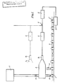
- the apparatus includes one or more dosing devices A which, through respective non-return nozzles B, fill open, gable-topped cartons C which are conveyed by a conveying device H through a top-sealing station to an electronic weighing scale D, where they arrive as sealed cartons C ⁇ .
- the scale D feeds weight data signals to a programmable logic controller E which through a multiplexed input/ output F itself feeds instructions to one or more indexer units G which control individual stepping motors 24.
- the or each device A is supplied with liquid from a liquid reservoir J through respective non-return valves K.
- Each unit G is provided with a selection of programmes specifically designed to give efficient filling of respective liquids of differing viscosities.
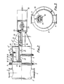
- the or each device A includes a housing 1 consisting of a cup-shaped casing 2 having an inlet 3 and an outlet 4 for a liquid being dosed, a tubular casing 5 and a casing 6 which is in the shape of a cup 6 ⁇ with a central, outward, tubular extension 6 ⁇ .
- the parts 6 ⁇ and 6 ⁇ are stabilized by fins 7 attached thereto.
- the casings 2 and 5 and the casings 5 and 6 are provided with respective flanges 8 fastened together by circular clamps (of which one is partially shown at 9) and have clamped between them respective rolling diaphragms 10 and 11.
- the diaphragm 10 is of a disc-like form with its central part attached to a cup-shaped member 12 which is co-axial with the housing 1.
- the diaphragm 11 is annular and has its inner peripheral edge clamped between the rim of the member 12 and an annular clamping member 13 attached by means of nut-and-bolt devices (of which one is seen and referenced 14) to the rim of the member 12.
- Fastened internally to the housing part 6 ⁇ is a horizontal, inverted, U-shaped channel 15 in which are mounted vertical rollers 16 which guide movement of a vertical fin 17 extending in a vertical plane containing the axis of the housing 1.
- the fin 17 is fixed to a horizontal sleeve 18 fastened co-axially at one end to the base of the cup-shaped member 12.
- the sleeve 18 is internally screwthreaded to receive an externally screw-threaded ring 19 constituting a backlash take-up device.
- the ring 19 is formed outside the sleeve 18 with a flange carrying grub screws (of which one is seen and referenced 20) tightenable against the adjacent axial end face of the sleeve 18 to prevent unintended unscrewing of the ring 19 from the sleeve 18.
- the shaft 22 rotates in ball bearings 24 between which is a spacer 26.
- the annular chamber 27 bounded by the casing 5, the diaphragms 10 and 11 and the member 12 communicates with a vacuum connection 28. The vacuum thereby produced in the chamber 27 serves to avoid incorrect folding of the diaphragms 10 and 11 as they are rolled to and fro.
- the motor 24 rotates the shaft 22 and thereby, through the ball nuts 21, produces horizontal movement of the sleeve 18 and thus the central part of the diaphragm 10, the rollers 16 serving to prevent rotation of the sleeve 18 about its horizontal axis.
- Rotation of the stepping motor 24 in the sense to produce outward movement of the member 12 draws in liquid through the non-return valve K and the inlet 3 to a volume determined by the extent of stepping movement of the motor 24.
- the motor 24 is put in reverse and the member 12 driven inwards to expel the desired volume of liquid through the outlet 4 and the filling nozzle B.
- the or each stepping motor 24 can be set on either full-step or half-step mode, the half-step mode giving 400 steps per revolution.
- the member 12 displaces approximately 0.25 grams per step. This displacement allows a 25mm. stroke to displace 500 grams.
- Using the half-step mode means that the weights can be calibrated to within 0.25 of a gram.
- the actual performance of the device A can be controlled by setting various speeds. This means that different products to be filled can each have an individual control programme specifically designed for the efficient filling of that product.
- the or each unit G is designed to change from a base programme to a different movement programme, on acceptance of different input conditions.
- the controller E can control the movement programmes required for the different weights of fill simply by weighing samples.
- the cartons are all conveyed in turn to the scale D and the average weight of a selected number of them is used to control the angular stroke of the motor 24 and thus the linear stroke of the member 12.
- cartons selected at intervals can be carried to the scale and then the cartons weighed in turn and the average weight automatically fed to the controller E.
- the dosing apparatus can fill a single line of cartons or a plurality of lines of cartons.
- a line number would be entered on the scales, then selected cartons would be weighed in turn. After each carton has been weighed an enter key would be pressed. On completion of a batch of the cartons, the average weight would be sent to the controller E and the appropriate unit G would be adjusted automatically.
- having the dosing apparatus drive independent of the machine drive in a container-filling machine enables the dosing apparatus to be run independently of the machine for cleaning the dosing apparatus in situ.
- the dosing apparatus described is also particularly applicable to aseptic filling.
- the programme control of the present apparatus facilitates matching the displacement and speed of the member 12 to the capacity of, say, the filling machine, and/or to the viscosity of the liquid. It can also achieve a very simple way of preventing dripping as filling stops, by producing a very short and fast outward movement of the member 12 as filling ceases, in order to draw the liquid back slightly at the outlet of the filling nozzle.
Landscapes
- Physics & Mathematics (AREA)
- Fluid Mechanics (AREA)
- General Physics & Mathematics (AREA)
- Basic Packing Technique (AREA)
- Supply Of Fluid Materials To The Packaging Location (AREA)
Applications Claiming Priority (2)
| Application Number | Priority Date | Filing Date | Title |
|---|---|---|---|
| GB878703985A GB8703985D0 (en) | 1987-02-20 | 1987-02-20 | Dosing apparatus |
| GB8703985 | 1987-02-20 |
Publications (2)
| Publication Number | Publication Date |
|---|---|
| EP0287201A2 true EP0287201A2 (de) | 1988-10-19 |
| EP0287201A3 EP0287201A3 (de) | 1988-11-23 |
Family
ID=10612639
Family Applications (1)
| Application Number | Title | Priority Date | Filing Date |
|---|---|---|---|
| EP88301496A Withdrawn EP0287201A3 (de) | 1987-02-20 | 1988-02-22 | Dosierapparat |
Country Status (4)
| Country | Link |
|---|---|
| US (1) | US4938271A (de) |
| EP (1) | EP0287201A3 (de) |
| JP (1) | JPS63248602A (de) |
| GB (1) | GB8703985D0 (de) |
Cited By (2)
| Publication number | Priority date | Publication date | Assignee | Title |
|---|---|---|---|---|
| WO1999057013A1 (en) | 1998-04-30 | 1999-11-11 | Elopak Systems Ag | Method and apparatus for dosing a fluid product |
| WO2000065316A1 (en) * | 1999-04-23 | 2000-11-02 | Nordson Corporation | Viscous material dispensing system and method with feedback control |
Families Citing this family (1)
| Publication number | Priority date | Publication date | Assignee | Title |
|---|---|---|---|---|
| JPH0662123B2 (ja) * | 1989-12-21 | 1994-08-17 | 日本エランコ株式会社 | カプセル充填装置 |
Family Cites Families (16)
| Publication number | Priority date | Publication date | Assignee | Title |
|---|---|---|---|---|
| US2763416A (en) * | 1951-06-25 | 1956-09-18 | Infilco Inc | Liquid filling apparatus |
| US2712408A (en) * | 1953-01-08 | 1955-07-05 | Herbert W Link | Apparatus for gauging contents of containers |
| CH408468A (de) * | 1964-03-16 | 1966-02-28 | Polymetron Ag | Bürette mit in einem Zylinder axial bewegbarem Kolben |
| US3648741A (en) * | 1970-04-23 | 1972-03-14 | American Can Co | Method and apparatus for accurately dispensing viscous products into successive containers |
| AT365779B (de) * | 1975-04-11 | 1982-02-10 | Richter Mess Regeltech | Praezisions-dosierpumpe mit impulsantrieb |
| CH627552A5 (en) * | 1978-03-31 | 1982-01-15 | Ciba Geigy Ag | Dosing device |
| DE2855751C2 (de) * | 1978-12-22 | 1984-03-15 | Waeschle Maschinenfabrik Gmbh, 7980 Ravensburg | Einrichtung zum pneumatischen Beschicken einer Behälterwaage |
| US4381545A (en) * | 1980-12-29 | 1983-04-26 | E. I. Du Pont De Nemours And Company | Control means and method for powder bagging |
| US4474309A (en) * | 1981-10-22 | 1984-10-02 | Oximetrix, Inc. | Stepping motor control procedure for achieving variable rate, quasi-continuous fluid infusion |
| US4437498A (en) * | 1981-11-09 | 1984-03-20 | Liquipak International, Inc. | Carton filling apparatus |
| IE54031B1 (en) * | 1982-01-29 | 1989-05-24 | Perkin Elmer Corp | Solvent delivery system |
| DE3213996A1 (de) * | 1982-04-16 | 1983-10-27 | Société d'Application Plastique, Mécanique et Electronique Plastimécanique S.A., 14700 Falaise | Fuell- und dosirvorrichtung fuer fluessige und pastoese nahrungsmittel |
| US4457348A (en) * | 1982-07-07 | 1984-07-03 | Mueller Martin J | Food product fill pump |
| DE3412628C2 (de) * | 1984-04-04 | 1986-05-15 | Benz & Hilgers GmbH, 4000 Düsseldorf | Vorrichtung zum dosierten Abfüllen von fließfähigem oder pastösem Füllgut in Behälter |
| DE3510110A1 (de) * | 1985-03-20 | 1986-10-02 | Walter Graf U. Co Gmbh & Co, 6980 Wertheim | Praezisionsdosiergeraet und verfahren zur praezisionsdosierung fluessiger medien |
| US4696329A (en) * | 1986-06-09 | 1987-09-29 | Mateer Burt Co., Inc. | Feedback control for automatic filling machine |
-
1987
- 1987-02-20 GB GB878703985A patent/GB8703985D0/en active Pending
-
1988
- 1988-02-19 US US07/158,249 patent/US4938271A/en not_active Expired - Fee Related
- 1988-02-19 JP JP63037308A patent/JPS63248602A/ja active Pending
- 1988-02-22 EP EP88301496A patent/EP0287201A3/de not_active Withdrawn
Cited By (4)
| Publication number | Priority date | Publication date | Assignee | Title |
|---|---|---|---|---|
| WO1999057013A1 (en) | 1998-04-30 | 1999-11-11 | Elopak Systems Ag | Method and apparatus for dosing a fluid product |
| WO2000065316A1 (en) * | 1999-04-23 | 2000-11-02 | Nordson Corporation | Viscous material dispensing system and method with feedback control |
| EP1754962A3 (de) * | 1999-04-23 | 2007-02-28 | Nordson Corporation | Abgabevorrichtung und Abgabeverfahren für viskoses Material mit Rückkoppelungsregelkreis |
| EP1890118A3 (de) * | 1999-04-23 | 2008-02-27 | Nordson Corporation | Ausgabesystem für visköses Material und Verfahren mit Feedback-Regelung |
Also Published As
| Publication number | Publication date |
|---|---|
| GB8703985D0 (en) | 1987-03-25 |
| EP0287201A3 (de) | 1988-11-23 |
| JPS63248602A (ja) | 1988-10-14 |
| US4938271A (en) | 1990-07-03 |
Similar Documents
| Publication | Publication Date | Title |
|---|---|---|
| US12269730B2 (en) | Cannabis concentrate dispensing system and method | |
| US4805673A (en) | Process and device for dispensing predetermined doses having a precise weight of a fluid filling material | |
| US4696329A (en) | Feedback control for automatic filling machine | |
| EP0125932B1 (de) | Kontrollapparat für und Verfahren zum Antrieb einer automatischen Füllmaschine | |
| US5787687A (en) | Servo-controlled container filling and weighing system | |
| EP3283208A1 (de) | Ausgabemaschine, insbesondere zur herstellung eines farbmusters | |
| EP0327183B1 (de) | Steuerungssystem für hin -und hergehende lineare Bewegung oder intermittierende Bewegungseinrichtungen | |
| US6722403B2 (en) | Automated apparatus for dispensing measured quantities of powder to containers in an array | |
| US4938271A (en) | Dosing apparatus | |
| CN210555657U (zh) | 一种中药配方颗粒瓶装机 | |
| EP0296801A2 (de) | Fülleinrichtung für Flüssigkeiten | |
| CN211642654U (zh) | 一种高精度粉剂灌装装置 | |
| CN217805691U (zh) | 包装机及其精确称重补料装置及其转运称重机构 | |
| US3770169A (en) | Motorized liquid dispenser with an accurate dispensing volume adjustment | |
| EP0107626A1 (de) | Anlage zum Dosieren von körnigen Produkten, insbesondere Nahrungsmitteln | |
| CN220640291U (zh) | 一种六头在线称重螺杆分装机 | |
| CN218288203U (zh) | 一种高效凝胶糖果填充机 | |
| US5016690A (en) | Dosing device on a filling plant, in particular for liquid and pasty products, and process for its operation | |
| CN218742858U (zh) | 一种用于芯片封装的点胶机构 | |
| JPH0662123B2 (ja) | カプセル充填装置 | |
| US4625775A (en) | High speed container placement apparatus | |
| US2490056A (en) | Measuring device using a rotating trap chamber having a varying peripheral speed | |
| WO2002098785A1 (en) | Precise filling method | |
| GB2127158A (en) | Batch weighing apparatus | |
| CN221198625U (zh) | 一种可调节烧结配料量的称重控制装置 |
Legal Events
| Date | Code | Title | Description |
|---|---|---|---|
| PUAI | Public reference made under article 153(3) epc to a published international application that has entered the european phase |
Free format text: ORIGINAL CODE: 0009012 |
|
| PUAL | Search report despatched |
Free format text: ORIGINAL CODE: 0009013 |
|
| AK | Designated contracting states |
Kind code of ref document: A2 Designated state(s): DE FR GB IT SE |
|
| AK | Designated contracting states |
Kind code of ref document: A3 Designated state(s): DE FR GB IT SE |
|
| 17P | Request for examination filed |
Effective date: 19890522 |
|
| 17Q | First examination report despatched |
Effective date: 19900827 |
|
| STAA | Information on the status of an ep patent application or granted ep patent |
Free format text: STATUS: THE APPLICATION IS DEEMED TO BE WITHDRAWN |
|
| 18D | Application deemed to be withdrawn |
Effective date: 19910108 |