EP0287221B1 - Semoirs de précision - Google Patents
Semoirs de précision Download PDFInfo
- Publication number
- EP0287221B1 EP0287221B1 EP88302342A EP88302342A EP0287221B1 EP 0287221 B1 EP0287221 B1 EP 0287221B1 EP 88302342 A EP88302342 A EP 88302342A EP 88302342 A EP88302342 A EP 88302342A EP 0287221 B1 EP0287221 B1 EP 0287221B1
- Authority
- EP
- European Patent Office
- Prior art keywords
- trough
- seeds
- drum
- seed
- machine according
- Prior art date
- Legal status (The legal status is an assumption and is not a legal conclusion. Google has not performed a legal analysis and makes no representation as to the accuracy of the status listed.)
- Expired - Lifetime
Links
Images


Classifications
-
- A—HUMAN NECESSITIES
- A01—AGRICULTURE; FORESTRY; ANIMAL HUSBANDRY; HUNTING; TRAPPING; FISHING
- A01G—HORTICULTURE; CULTIVATION OF VEGETABLES, FLOWERS, RICE, FRUIT, VINES, HOPS OR SEAWEED; FORESTRY; WATERING
- A01G9/00—Cultivation in receptacles, forcing-frames or greenhouses; Edging for beds, lawn or the like
- A01G9/08—Devices for filling-up flower-pots or pots for seedlings; Devices for setting plants or seeds in pots
- A01G9/085—Devices for setting seeds in pots
-
- A—HUMAN NECESSITIES
- A01—AGRICULTURE; FORESTRY; ANIMAL HUSBANDRY; HUNTING; TRAPPING; FISHING
- A01C—PLANTING; SOWING; FERTILISING
- A01C7/00—Sowing
- A01C7/04—Single-grain seeders with or without suction devices
- A01C7/042—Single-grain seeders with or without suction devices using pneumatic means
- A01C7/044—Pneumatic seed wheels
-
- Y—GENERAL TAGGING OF NEW TECHNOLOGICAL DEVELOPMENTS; GENERAL TAGGING OF CROSS-SECTIONAL TECHNOLOGIES SPANNING OVER SEVERAL SECTIONS OF THE IPC; TECHNICAL SUBJECTS COVERED BY FORMER USPC CROSS-REFERENCE ART COLLECTIONS [XRACs] AND DIGESTS
- Y10—TECHNICAL SUBJECTS COVERED BY FORMER USPC
- Y10S—TECHNICAL SUBJECTS COVERED BY FORMER USPC CROSS-REFERENCE ART COLLECTIONS [XRACs] AND DIGESTS
- Y10S47/00—Plant husbandry
- Y10S47/901—Plant container with flats, filling, planting, or conveying
Definitions
- the present invention relates to seeding machines.
- European Patent No. 0 193 411 discloses a seeding machine having a rotary drum partially immersed in a reservoir containing seeds.
- the drum has a plurality of holes in its outer circumferential surface, which holes can alternately be connected to a source of vacuum and source of pressure.
- a source of vacuum and source of pressure As each hole passes through the mass of seeds in the reservoir, the vacuum applied draws the nearest seed to close or partially close the hole.
- the drum rotates the attracted seed is lifted out of the mass of seeds and when the seed reaches a discharge position a source of pressure is applied to the particular hole to shoot the seed to a desired discharge tube or location.
- the disadvantage of this arrangement is that the seeds in the mass of seeds do not move readily so that when seeds are picked out of the mass at a predetermined withdrawal location, they are not readily replaced by adjacent seeds. Instead a hole is created in the mass at the withdrawal location so that no further seeds are withdrawn.
- a further problem which occurs because the seeds do not have sufficient mobility is that a seed attracted to a hole and carried round by the drum may well engage a seed located in front of it and push the seed along towards the discharge position.
- a seeding machine comprising first and second surfaces constrained to make contact along a common axis and thereafter separating to define a seed trough, means for continuously displacing one said surface away from the common axis said one surface defining a plurality of openings which can be coupled to a source of pressure difference to attract an individual seed to each opening and to allow the surface to carry the individual seeds to a location for discharge, characterised by means for continuously displacing the other said surface away from the common axis whereby to cause any seeds in the trough to tumble continuously.
- a seeding machine comprising a rotary drum defining a plurality of axially extending rows of openings, a member urged into contact with the drum to define with the drum a seed trough, drive means for rotating the drum, and means for effecting a pressure difference across each opening to cause it to attract a seed as it passes through the trough and to carry the attracted seed to a location for discharge characterised in that said member comprises a roller and in that said drive means is arranged to rotate the drum and roller in opposite senses so that the facing surfaces of the drum and roller are continuously rising out of the trough to tumble any seeds which have been deposited in the trough.
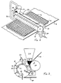
- the seeding machine shown in Figures 1 and 2 is arranged to dispense seeds one row at a time into a seed tray 2 having rows and columns of individual pockets filled with a seed compost (not shown).
- the seed tray 2 is arranged to be displaced through the seeding machine by a conveyor belt 6 which carries the tray 2.
- the machine comprises an elongate rotary drum 8 and an elongate rotary roller 10 arranged in mating engagement with the drum 8.
- the drum 8 and roller 10 are mounted between two spaced side plates (not shown) by bearings (not shown) with their axes extending parallel to one another.
- the drum 8 is provided with a plurality of internal axially extending equi-angularly spaced air channels 12 (see Figure 2). Each channel 12 communicates with a corresponding axially extending row of holes 14 in the circumferential surface of the drum.
- the drum 8 is in sliding contact with a support plate (not shown).
- An arcuate groove 16 in the support plate and coupled to a source of vacuum (not shown) is located along the locus of the adjacent axial ends of the channels 12. Thus as each channel 12 becomes aligned with the arcuate groove 16, the channel 12 is subjected to a vacuum.
- each aperture is coupled to a source of pressure (not shown). As each channel 12 becomes aligned with the apertures 18 and 20, the channel is subject to a blast of air under pressure.
- the drum 8 and the roller 10 define a trough 22 into which seeds can be poured.
- a hopper 24 is provided adjacent one end of the trough 22 to feed a constant supply of seeds to the trough 22.
- the hopper 24 may have an adjustable outlet to regulate the flow rate of seeds therefrom.
- Extending into the trough at the end adjacent the hopper 24 is a wall of bristles 26 mounted on a support 28. The wall of bristles 26 prevents any seeds from falling out of the trough 22 at that end.
- the opposite end of the trough 22 is open.
- a funnel 30 is located below the open end of the trough 22 to catch the seeds falling therefrom.
- the funnel 30 communicates with a conduit 32 which extends parallel to the axis of the drum 8 and roller 10 and passes under the roller 10 to rise at the other side to a position where it is directed downwardly into the hopper 24.
- the conduit 32 is supplied with air under pressure which drives any seeds entering the conduit 32 from the funnel 30, along the conduit to be discharged into the hopper 24.
- a hollow tube 34 extending parallel with the drum 8 is located above the drum 8.
- the tube 34 which is connected to a source of pressure (not shown) is provided with a row of holes to direct air jets at the surface of the drum 8 to dislodge any seeds, clinging only loosely to the drum surface, back into the trough 22.
- a doctor blade 36 engages the roller 10 in an upper portion of the trough 22 to dislodge any seeds clinging to the surface of the roller 10 to return them to the trough 22.
- a drive assembly (not shown) drives the roller 10 and the drum 8 in opposite senses so that the surfaces of the roller 10 and drum 8 which define the opposite walls of the trough 22 are always rising upwardly out of the trough 22.
- the seed tray 2 In operation when a seed tray 2 is to be planted with seeds, the seed tray 2 is indexed under the drum 8 at the same pace as the circumferential speed of the drum 8.
- the hopper 24 is loaded with a supply of seeds which run from the base of the hopper along the trough 22 to spill out of the end of the trough into the funnel 30. Seeds entering the funnel 30 are then returned to the hopper along the conduit 32 by an air flow.
- the drum 8 and the roller are rotated in opposite directions so that the rising sides of the trough 22, which are in frictional engagement with the seeds, raise the seeds to a level at which they fall again under gravity.
- the seeds in the trough 22 are thus kept continually in motion which helps the flow of seeds along the trough 22 and also tends to effect the separation of seeds from one another.
- each row of holes enters the trough 22 in turn.
- the conduit 12 with which the row is associated communicates with the arcuate groove 16 and the holes are subjected to a vacuum.
- the vacuum force draws a seed from the trough 22 to close or partially close each hole in the row.
- the vacuum for each row of holes is held while the row moves through the highest point of the drum until it approaches the lowest point. At this point the conduct 12 associated with the row becomes disconnected from the arcuate groove 16 and the vacuum force to the holes ceases.
- the conduit 12 With continual rotation of the drum 8 the conduit 12 is brought into alignment with the small aperture 18 which then supplies low pressure air to the holes to dislodge, into the waiting pockets 4, any seeds which did not become released from the drum 8 upon discontinuance of the vacuum. As the drum 8 continues to rotate a doctor blade 40 of Tufnol or similar material scrapes any stubborn remaining seed from the drum surface. Finally when the conduit 20 aligns itself with the larger aperture 20 a much stronger blast of air is applied to the row of openings with a view to unclogging any aperture which had become inadvertently clogged.
- the air jet from the tube 34 is preferably arranged at an angle of 45° to the tangent to the portion of the drum 8 lying directly below the tube 34.
- the tube 34 may be provided with an additional jet for each hole in the drum directed to blow any seeds away from the trough.
- the two jets in the tube 34 for each hole in the drum may be arranged at 90° to each other. Excess seeds removed by this jet are caught in the trough 41.
- two half length rollers 10A and 10B are provided axially spaced from one another, to leave a central gap in the trough 22 through which seeds can fall.
- a funnel 30 located below the gap collects the fallen seeds and by means of an air assisted return conduit feeds the collected seeds back to one or both hoppers 24 and 24B.
- the drum is formed from two components, an outer sleeve 50 of hard anodised aluminium with holes 52 arranged in separate axially extending rows, and an inner core 54 of cast aluminium comprising an inner cylinder 56 with twelve radially projecting equi-angularly spaced fins 58.
- the inner core 54 is placed within the outer sleeve 50 so that the distal ends of the fins seal against the inner wall of the sleeve 50. This can be accomplished by adopting shrink fit procedures, using adhesives, or even welding.
- the fins define twelve axially extending channels. For normal seeding operations only six channels are needed and so every alternate channel is filled with an impermeable medium 60. The remaining six intervening channels communicate with respective rows of holes.
- the drum is sealed at one axial end and to the other axial end is secured an annular ring 62 of plastics impregnated with graphite.
- O-rings 63 provide a seal between each channel in the drum and respective ones of six through holes 70 in the annular ring 62.
- the annular ring 62 is mounted on a stub shaft 72 extending from an end support 62.
- the end support 64 has an annular end face which is in sliding engagement with the annular ring 6. This annular end face is profiled to define the arcuate groove 16 and the apertures 18 and 20 shown in Figure 2.
- the end support 64 carries a coupling spigot 68 which is coupled to a source of vacuum 69 through a hose line 71, the coupling spigot 68 being in communication with the groove 16.
- the end support also carries another coupling spigot 70 which is coupled to a source of pressure 75 by a hose line 73; the coupling spigot 70 being in communication with the two apertures 18 and 20.
- the drum 8 is driven by an electric motor (not shown).
- the drum 8 and the roller 10 are coupled by gears to ensure that their surface velocity is the same at the point of contact between the roller 8 and the drum 10.
- the roller 80 is narrow and positioned opposite an intermediate section of the roller 10 to provide pressure on the roller 10 and hence on the drum to ensure close contact between the drum and the roller. Another advantage of this arrangement is that the rollers 10 and 80 can be easily separated for cleaning or servicing purposes.
- Figure 7 also shows a modification for sweeping the drum 8 clean from unwanted seeds.
- a pivotally supported arm 94 carries a brush head 96 at its free end. Bristles or rubber strips extending from the brush head engage the drum. As the drum 8 rotates the bristles sweep the drum clean.
- a rotary cam 92 engaging the arm 94 is rotated in synchronism with the drum so that each time a row of holes in the drum passes the bristles, the arm 94 and therefore the bristles are lifted to allow the holes and the seeds which are attracted to the holes free passage. As soon as each row of holes has passed the cam 92 allows the arm 94 to drop to bring the bristles back into engagement with the drum again.
Landscapes
- Life Sciences & Earth Sciences (AREA)
- Environmental Sciences (AREA)
- Soil Sciences (AREA)
- Sowing (AREA)
- Noodles (AREA)
- Soil Working Implements (AREA)
- Pretreatment Of Seeds And Plants (AREA)
Claims (15)
- Machine pour semer comprenant une première et une seconde surfaces (8, 10) contraintes d'être en contact le long d'un axe commun et, après, de se séparer pour définir une auge (22) pour semences, un moyen pour déplacer continuellement l'une (8) desdites surfaces en l'éloignant de l'axe commun, cette surface (8) définissant une pluralité d'ouvertures (14) qui peuvent être reliées à une source de pression différentielle pour attirer une semence individuelle à chaque ouverture (14) et pour permettre à la surface de porter les semences individuelles à un endroit prévu pour leur déchargement, caractérisée par un moyen (80) pour déplacer continuellement l'autre surface (10) en l'éloignant de l'axe commun afin de faire que toutes les semences contenues dans l'auge tombent continuellement.
- Machine pour semer comprenant un tambour rotatif (8) définissant une pluralité de rangée d'ouvertures (14) s'étendant en sens axial, un moyen poussé pour être en contact avec le tambour (8) pour définir avec ce tambour(8) une auge pour semences, un moyen d'entraînement pour faire tourner le tambour et un moyen pour créer une pression différentielle à travers chaque ouverture (14) afin de l'obliger à attirer une graine au moment de son passage à travers l'auge et de porter la graine attirée jusqu'à un endroit prévu pour le déchargement, caractérisée en ce que ledit organe comprend un rouleau (10) et en ce que le moyen d'entraînement (80) est disposé pour faire tourner le tambour (8) et le rouleau (10) dans des sens opposés de sorte que les faces en regard du tambour (8) et du rouleau (10) sont continuellement montantes hors de l'auge pour faire tomber toutes les semences qui ont été déposées dans cette auge.
- Machine selon la revendication 2, caractérisée par une trémie (24) pour semences montée au-dessus de l'auge (22) pour alimenter cette auge (22) d'un courant continu de semences de manière à induire un courant de semences le long de l'auge.
- Machine selon la revendication 3, caractérisée par un moyen servant de porte pour contrôler le débit auquel les semences sont fournies à partir de la trémie (24).
- Machine selon la revendication 3 ou la revendication 4, caractérisée par un moyen (30) pour recueillir le courant de débordement des semences hors de l'auge (22) et pour renvoyer celles-ci à la trémie (24).
- Machine selon l'une quelconque des revendications précédentes, caractérisée par un moyen (26, 28) d'arrêt extrême situé au voisinage d'au moins une extrémité de l'auge (22) pour empêcher la fuite de semences par cette extrémité de l'auge (22).
- Machine selon la revendication 6, caractérisée en ce que le moyen d'arrêt extrême comprend une paroi de poils (26) en contact glissant avec les parois opposées de l'auge (22).
- Machine selon la revendication 2, caractérisée par une trémie (24) pour semences située au voisinage d'une extrémité de l'auge (22) pour fournir une alimentation continue de semences à cette auge (22), un arrêt d'extrémité (26, 28) pour empêcher le passage des semences à une extrémité de l'auge (22), un moyen (30) servant d'entonnoir situé en-dessous de l'autre extrémité de l'auge (22) pour recueillir les graines déchargées par cette extrêmité de l'auge (22) et un moyen (32) pour renvoyer les semences de l'entonnoir (30) à la trémie (24) pour semences.
- Machine selon la revendication 2, caractérisée par deux trémies (24, 24A) situées chacune respectivement à une des extrémités de l'auge (22), deux arrêts d'extrémité (28, 28A) situés chacun respectivement aux extrémités de l'auge (22) pour empêcher le passage des semences au-delà des extrémités de cette auge (22), le rouleau (10) ayant une discontinuité intermédiaire pour procurer un intervalle à travers lequel les semences peuvent être déchargées de l'auge (22), un moyen (30) servant d'entonnoir situé en-dessous de cet intervalle pour recueillir les semences déchargées de l'auge (22) et un moyen pour renvoyer de l'entonnoir (30) aux trémies (24, 24A) les semences déchargées.
- Machine selon la revendication 8 ou la revendication 9, caractérisée en ce que le moyen pour renvoyer des semences comprend un conduit s'étendant à partir de l'entonnoir (30) jusqu'à la trémie (24, 24A) et des moyens de fourniture d'air raccordés au conduit pour entraîner les semences entrant dans le conduit en provenance de l'entonnoir (30) le long du conduit jusqu'à la trémie (24, 24A).
- Machine selon l'une quelconque des revendications 2 à 5 et 8 à 10, caractérisée par un moyen (34) à jets d'air situé au-dessus du tambour (8) et disposé pour diriger la rangée des jets d'air vers lesdites rangées de trous quand ceux-ci émergent de l'auge afin de déranger tout amas de graines groupées autour d'un unique trou et pour envoyer toute semence délogée dudit amas en retour à ladite auge.
- Machine selon la revendication 11, caractérisée en ce que le moyen (34) à jets d'air procure une seconde rangée de jets d'air dirigée vers les rangées de trous lorsque ceux-ci ont passé le moyen à jets d'air pour créer un dérangement supplémentaire de tout amas subsistant de semences.
- Machine selon l'une quelconque des revendications 2 à 5 et 8 à 12, caractérisée par un moyen (98) servant de brosse pour brosser la surface extérieure du tambour (8) quand il émerge de l'auge (22) et un moyen (92) servant de came pour soulever le moyen (88) servant de brosse par rapport au tambour (8) à mesure que chaque rangée de trous passe devant ce moyen (98) servant de brosse de sorte que les semences portées par chaque rangée restent non dérangées par le moyen (98) servant de brosse.
- Machine selon l'une quelconque des revendications 2 à 5 et 8 à 13, caractérisée en ce que le rouleau (10) est monté sur un support pivotant pour effectuer un mouvement de rapprochement et d'éloignement par rapport au tambour (8) et comprenant un cylindre d'engagement (80) monté aussi sur un support pivotant (82) et un moyen de rappel (90) pour rappeler le cylindre d'engagement (80) en contact avec le premier rouleau mentionné (10) pour obliger ce premier rouleau mentionné (10) à rester en contact serré avec le tambour (8).
- Machine selon l'une quelconque des revendications 2 à 5 et 8 à 14, caractérisée en ce que le tambour (8) comprend un noyau intérieur (54) ayant un élément cylindrique (56) comportant une pluralité d'ailettes (58) s'étendant en sens radial, espacées circonférentiellement, et un manchon extérieur (50) entourant le noyau (54) de sorte que les extrêmités distales des ailettes (58) sont engagées de manière étanche avec la face intérieure du manchon (50) pour définir une pluralité de canaux d'air (12) s'étendant en sens axial et des rangées de trous (52) prévus dans le manchon extérieur (50), chaque rangée étant en communication avec un canal différent desdits canaux (12).
Priority Applications (1)
| Application Number | Priority Date | Filing Date | Title |
|---|---|---|---|
| AT88302342T ATE72724T1 (de) | 1987-04-11 | 1988-03-17 | Saemaschinen. |
Applications Claiming Priority (2)
| Application Number | Priority Date | Filing Date | Title |
|---|---|---|---|
| GB8708734 | 1987-04-11 | ||
| GB8708734A GB2203021B (en) | 1987-04-11 | 1987-04-11 | Seeding machines |
Publications (2)
| Publication Number | Publication Date |
|---|---|
| EP0287221A1 EP0287221A1 (fr) | 1988-10-19 |
| EP0287221B1 true EP0287221B1 (fr) | 1992-02-26 |
Family
ID=10615684
Family Applications (1)
| Application Number | Title | Priority Date | Filing Date |
|---|---|---|---|
| EP88302342A Expired - Lifetime EP0287221B1 (fr) | 1987-04-11 | 1988-03-17 | Semoirs de précision |
Country Status (6)
| Country | Link |
|---|---|
| US (2) | US4926583A (fr) |
| EP (1) | EP0287221B1 (fr) |
| AT (1) | ATE72724T1 (fr) |
| CA (1) | CA1302791C (fr) |
| DE (1) | DE3868529D1 (fr) |
| GB (1) | GB2203021B (fr) |
Families Citing this family (18)
| Publication number | Priority date | Publication date | Assignee | Title |
|---|---|---|---|---|
| GB2229616A (en) * | 1989-03-10 | 1990-10-03 | Specialised Harvesting Service | Improvements in or relating to seed dispensing apparatus |
| FR2647298A1 (fr) * | 1989-05-25 | 1990-11-30 | Billard Jean | Dispositif de distribution monograine pneumatique pour semoir polyvalent |
| US5573558A (en) * | 1991-03-11 | 1996-11-12 | Huang; Barney K. | Automatic transplanting system |
| US5254140A (en) * | 1991-03-11 | 1993-10-19 | Huang Barney K | Plant transferring and transplanting system |
| US5414955A (en) | 1994-08-03 | 1995-05-16 | Morin; Thomas M. | Hand held seeder |
| CN1058365C (zh) * | 1994-10-07 | 2000-11-15 | 华方吉 | 种籽点播机 |
| GB2301787B (en) * | 1995-05-16 | 1999-11-10 | Semelab Plc | Separating and sequencing apparatus |
| NO960209A (no) * | 1996-01-17 | 1997-06-30 | Vefi As | Såmaskin |
| EP1722236A1 (fr) * | 1999-02-16 | 2006-11-15 | Applera Corporation | Système de distribution de perles |
| US6053220A (en) * | 1999-03-31 | 2000-04-25 | Lo; Kuang-Sheng | Volume-based auto seed-dispensing apparatus |
| US6634305B1 (en) * | 2002-04-12 | 2003-10-21 | John E. Braun | Seed planting system |
| WO2007130434A2 (fr) * | 2006-05-02 | 2007-11-15 | Applera Corporation | Distributeur de volume variable et procédé |
| DE202012010987U1 (de) | 2012-11-15 | 2012-12-04 | Harry Schneckenburger | Vakuumstift für Sämereien |
| US9545123B2 (en) * | 2013-11-12 | 2017-01-17 | Axis Automation Llc | Food topping dispenser with application roller for dusting food products |
| CA2960677C (fr) * | 2016-04-28 | 2022-04-12 | Gerard DEVLOO | Broyeur d'echantillon de semence de canola |
| CN109348916A (zh) * | 2018-11-02 | 2019-02-19 | 合肥霞康电子商务有限公司 | 一种育苗盘压穴装置 |
| CN109511421B (zh) * | 2018-11-28 | 2021-10-22 | 丁浩 | 农业大棚用育苗装置 |
| CN115024052B (zh) * | 2022-07-08 | 2023-07-25 | 甘肃农业大学 | 一种直插穴播器 |
Family Cites Families (16)
| Publication number | Priority date | Publication date | Assignee | Title |
|---|---|---|---|---|
| US19294A (en) * | 1858-02-09 | Improvement in potato-planters | ||
| US1261402A (en) * | 1916-12-16 | 1918-04-02 | Joseph G Journeay | Match-dispensing machine. |
| US1497576A (en) * | 1923-08-20 | 1924-06-10 | Molins Walter Everett | Apparatus for feeding cigarettes and other small articles |
| US1637834A (en) * | 1925-10-02 | 1927-08-02 | Melfort V Oliver | Seed planter |
| US1976351A (en) * | 1932-12-16 | 1934-10-09 | John C Matthiesen | Dispensing device |
| US2696327A (en) * | 1949-07-16 | 1954-12-07 | Bauer Bros Co | Wire feeder |
| NL6407284A (fr) * | 1964-06-26 | 1965-12-27 | ||
| US3715056A (en) * | 1969-12-31 | 1973-02-06 | Molins Machine Co Ltd | Handling apparatus for rod-like articles |
| US4026437A (en) * | 1974-11-22 | 1977-05-31 | Cambridge Consultants Ltd. | Seed drill |
| SE394847B (sv) * | 1975-06-05 | 1977-07-18 | Wendt K L | Sett och anordning for astadkommande av enkelradiga floden av fron |
| CA1111873A (fr) * | 1978-03-29 | 1981-11-03 | Athos Cristiani | Dispositif d'avancement pour articles en forme de tige |
| SE424801B (sv) * | 1980-12-19 | 1982-08-16 | Andersson Alf Ingf Hb | Anordning for radsadd av fron med forutbestemda inbordes mellanrum |
| JPS59163218A (ja) * | 1983-03-04 | 1984-09-14 | Takeda Chem Ind Ltd | 固形製剤の供給装置 |
| IT1204754B (it) * | 1985-02-01 | 1989-03-10 | Hauni Werke Koerber & Co Kg | Dispositivo per trasferire automaticamente grani di semi da una riserva di semi in un recipiente o verso superfici di semina. |
| US4718363A (en) * | 1985-02-28 | 1988-01-12 | Williames Hi-Tech Int'l Pty Ltd. | Multi-purpose seeding machine |
| GB2178289B (en) * | 1985-06-26 | 1989-07-12 | Specialised Harvesting Service | Seeding apparatus |
-
1987
- 1987-04-11 GB GB8708734A patent/GB2203021B/en not_active Expired - Fee Related
-
1988
- 1988-03-17 AT AT88302342T patent/ATE72724T1/de not_active IP Right Cessation
- 1988-03-17 DE DE8888302342T patent/DE3868529D1/de not_active Expired - Fee Related
- 1988-03-17 EP EP88302342A patent/EP0287221B1/fr not_active Expired - Lifetime
- 1988-03-28 US US07/174,247 patent/US4926583A/en not_active Expired - Fee Related
- 1988-04-08 CA CA000563584A patent/CA1302791C/fr not_active Expired - Lifetime
-
1990
- 1990-02-28 US US07/486,439 patent/US5048226A/en not_active Expired - Lifetime
Also Published As
| Publication number | Publication date |
|---|---|
| ATE72724T1 (de) | 1992-03-15 |
| US4926583A (en) | 1990-05-22 |
| EP0287221A1 (fr) | 1988-10-19 |
| US5048226A (en) | 1991-09-17 |
| GB8708734D0 (en) | 1987-05-20 |
| CA1302791C (fr) | 1992-06-09 |
| DE3868529D1 (de) | 1992-04-02 |
| GB2203021A (en) | 1988-10-12 |
| GB2203021B (en) | 1990-03-07 |
Similar Documents
| Publication | Publication Date | Title |
|---|---|---|
| US4926583A (en) | Apparatus for selecting and discharging seeds | |
| EP0193411B1 (fr) | Semoir polyvalent | |
| US4092046A (en) | Pneumatic feeder-dispenser for bulk material | |
| KR101928542B1 (ko) | 홍합의 세척, 분리 및 선별장치 | |
| CN113619821B (zh) | 一种可除去饲料粉渣的饲料灌装装置 | |
| CN110313277A (zh) | 一种智能双充种型孔滚筒水稻精密播种装置和播种方法 | |
| CN109076892A (zh) | 一种蔬菜快速种植方法 | |
| CN102365218B (zh) | 具有环带式种子传输元件的压差排种器 | |
| US5927908A (en) | Powder collecting and transporting device | |
| US12357145B2 (en) | Pan cleaning machine and a method of operating the machine to clean pans | |
| EP0374141B1 (fr) | Appareil de nettoyage et de distribution automatiques de balles de golf | |
| CN117751730B (zh) | 一种气吸滚筒式排种器及播种机 | |
| KR101940520B1 (ko) | 수리 보수가 용이한 어류용 사료급여기 | |
| CN117465922A (zh) | 一种分馅机的馅料传送装置 | |
| RU2137337C1 (ru) | Высевающий аппарат | |
| CN223652702U (zh) | 一种滚筒播种机 | |
| BRPI0515205B1 (pt) | conjuntos guias de frutas e método de fabricação de um corpo guia de frutas | |
| JPH0824193A (ja) | 食器などの洗浄装置 | |
| US4186092A (en) | Vacuum belt filters | |
| RU218188U1 (ru) | Высевающий аппарат | |
| CN220925442U (zh) | 一种具有自动清洁功能的输送链板 | |
| RU218138U1 (ru) | Высевающий аппарат для гнездового посева | |
| CN111819964B (zh) | 玉米试验播种机及用该播种机播种的方法 | |
| CH715524B1 (de) | Vereinzelungsvorrichtung zur Vereinzelung von kornförmigem Saatgut und Einzelkornsämaschine mit wenigstens einer solchen Vereinzelungsvorrichtung. | |
| RU2075275C1 (ru) | Пневматический высевающий аппарат |
Legal Events
| Date | Code | Title | Description |
|---|---|---|---|
| PUAI | Public reference made under article 153(3) epc to a published international application that has entered the european phase |
Free format text: ORIGINAL CODE: 0009012 |
|
| AK | Designated contracting states |
Kind code of ref document: A1 Designated state(s): AT BE CH DE ES FR GB GR IT LI LU NL SE |
|
| 17P | Request for examination filed |
Effective date: 19890124 |
|
| 17Q | First examination report despatched |
Effective date: 19900730 |
|
| GRAA | (expected) grant |
Free format text: ORIGINAL CODE: 0009210 |
|
| AK | Designated contracting states |
Kind code of ref document: B1 Designated state(s): AT BE CH DE ES FR GB GR IT LI LU NL SE |
|
| PG25 | Lapsed in a contracting state [announced via postgrant information from national office to epo] |
Ref country code: IT Free format text: LAPSE BECAUSE OF FAILURE TO SUBMIT A TRANSLATION OF THE DESCRIPTION OR TO PAY THE FEE WITHIN THE PRE;WARNING: LAPSES OF ITALIAN PATENTS WITH EFFECTIVE DATE BEFORE 2007 MAY HAVE OCCURRED AT ANY TIME BEFORE 2007. THE CORRECT EFFECTIVE DATE MAY BE DIFFERENT FROM THE ONE RECORDED.SCRIBED TIME-LIMIT Effective date: 19920226 Ref country code: AT Effective date: 19920226 Ref country code: GR Free format text: LAPSE BECAUSE OF FAILURE TO SUBMIT A TRANSLATION OF THE DESCRIPTION OR TO PAY THE FEE WITHIN THE PRESCRIBED TIME-LIMIT Effective date: 19920226 Ref country code: BE Effective date: 19920226 Ref country code: LI Effective date: 19920226 Ref country code: SE Effective date: 19920226 Ref country code: CH Effective date: 19920226 Ref country code: ES Free format text: THE PATENT HAS BEEN ANNULLED BY A DECISION OF A NATIONAL AUTHORITY Effective date: 19920226 |
|
| REF | Corresponds to: |
Ref document number: 72724 Country of ref document: AT Date of ref document: 19920315 Kind code of ref document: T |
|
| PG25 | Lapsed in a contracting state [announced via postgrant information from national office to epo] |
Ref country code: LU Free format text: LAPSE BECAUSE OF NON-PAYMENT OF DUE FEES Effective date: 19920331 |
|
| REF | Corresponds to: |
Ref document number: 3868529 Country of ref document: DE Date of ref document: 19920402 |
|
| ET | Fr: translation filed | ||
| REG | Reference to a national code |
Ref country code: CH Ref legal event code: PL |
|
| PLBE | No opposition filed within time limit |
Free format text: ORIGINAL CODE: 0009261 |
|
| STAA | Information on the status of an ep patent application or granted ep patent |
Free format text: STATUS: NO OPPOSITION FILED WITHIN TIME LIMIT |
|
| 26N | No opposition filed | ||
| PGFP | Annual fee paid to national office [announced via postgrant information from national office to epo] |
Ref country code: FR Payment date: 19930225 Year of fee payment: 6 |
|
| PGFP | Annual fee paid to national office [announced via postgrant information from national office to epo] |
Ref country code: DE Payment date: 19930324 Year of fee payment: 6 |
|
| PG25 | Lapsed in a contracting state [announced via postgrant information from national office to epo] |
Ref country code: FR Effective date: 19941130 |
|
| PG25 | Lapsed in a contracting state [announced via postgrant information from national office to epo] |
Ref country code: DE Effective date: 19941201 |
|
| REG | Reference to a national code |
Ref country code: FR Ref legal event code: ST |
|
| REG | Reference to a national code |
Ref country code: GB Ref legal event code: IF02 |
|
| PGFP | Annual fee paid to national office [announced via postgrant information from national office to epo] |
Ref country code: GB Payment date: 20070126 Year of fee payment: 20 |
|
| PGFP | Annual fee paid to national office [announced via postgrant information from national office to epo] |
Ref country code: NL Payment date: 20070330 Year of fee payment: 20 |
|
| REG | Reference to a national code |
Ref country code: GB Ref legal event code: PE20 Expiry date: 20080316 |
|
| PG25 | Lapsed in a contracting state [announced via postgrant information from national office to epo] |
Ref country code: NL Free format text: LAPSE BECAUSE OF EXPIRATION OF PROTECTION Effective date: 20080317 |
|
| NLV7 | Nl: ceased due to reaching the maximum lifetime of a patent |
Effective date: 20080317 |
|
| PG25 | Lapsed in a contracting state [announced via postgrant information from national office to epo] |
Ref country code: GB Free format text: LAPSE BECAUSE OF EXPIRATION OF PROTECTION Effective date: 20080316 |