EP0287237B1 - Porte-mine - Google Patents
Porte-mine Download PDFInfo
- Publication number
- EP0287237B1 EP0287237B1 EP88302789A EP88302789A EP0287237B1 EP 0287237 B1 EP0287237 B1 EP 0287237B1 EP 88302789 A EP88302789 A EP 88302789A EP 88302789 A EP88302789 A EP 88302789A EP 0287237 B1 EP0287237 B1 EP 0287237B1
- Authority
- EP
- European Patent Office
- Prior art keywords
- lead
- slider
- sleeve
- chuck
- stopper
- Prior art date
- Legal status (The legal status is an assumption and is not a legal conclusion. Google has not performed a legal analysis and makes no representation as to the accuracy of the status listed.)
- Expired
Links
Images


Classifications
-
- B—PERFORMING OPERATIONS; TRANSPORTING
- B43—WRITING OR DRAWING IMPLEMENTS; BUREAU ACCESSORIES
- B43K—IMPLEMENTS FOR WRITING OR DRAWING
- B43K21/00—Propelling pencils
- B43K21/02—Writing-core feeding mechanisms
- B43K21/027—Writing-core feeding mechanisms with sliding tubelike writing-core guide
- B43K21/033—Writing-core feeding mechanisms with sliding tubelike writing-core guide with automatic feed by pressure during use of pencil
Definitions
- the present invention relates to a mechanical pencil in which lead feed is done automatically upon release of writing of a slider from the paper surface or the like and the slider can be locked in a retreated position when the pencil is not in use.
- lead feed can be effected in three ways (automatic writing, front-end knock and rear-end knock) under a relatively simple internal structure.
- front-end knock the lead is fed, of course, when it is not projecting from the front end, while when the lead is projecting in excess of a predetermined amount, it is not fed any further, with only cushioning being performed.
- the foregoing known automatic mechanical pencils and the mechanical pencil of the above prior application are of a structure in which the slider moves alone and the lead is fed out by such movement. Therefore, in carrying the pencil after use, for example when the pencil is put into a pocket, the slider may retreat unnecessarily, allowing only the lead to be fed out inadvertently, thus causing stain of the clothing or breakage of the lead.
- a conventional lead stopper mounted in the interior of the front end side of a mechanical pencil to exert a predetermined frictional force on the lead is constituted by a friction imparting member provided in the interior of a tip member of the mechanical pencil or in the interior of a slider which is slidable axially in the interior of the tip member.
- the friction imparting member is integrally formed in the shape of a stepped cylinder comprising a cylindrical portion of a large diameter located on the front end side and a cylindrical portion of a large diameter on the rear end side, with a lead insertion hole being formed through the axes of those cylindrical portions.
- the friction imparting member is mounted by press-fitting into the tip member or the slider with its small-diameter cylindrical portion facing forward, whereby the entire outer peripheral surface of the friction imparting member is held in frictional engagement with the inner peripheral surface of the tip member or the slider.
- the outside diameter of the lead is 0.58 mm
- the inside diameter of the lead insertion hole of the friction imparting member is 0.53 mm
- the outside diameter of the lead insertion hole is 1.87 mm
- the inside diameter of the slider is 1.77 mm
- this expansion cannot be absorbed by the friction imparting member which is incapable of undergoing elastic deformation in the diameter expanding direction. Consequently, it becomes no longer possible to impart an appropriate frictional force to the lead and so it becomes impossible to prevent drop-out of the lead and attain stable support and smooth lead feed operation.
- the friction imparting member is formed in the shape of a stepped cylinder and has directionality at the time of mounting, etc., its mounting work is less efficient and the molding die required becomes complicated in structure, thus leading to increase of the cost.
- the conventional lead chuck is an integral chuck having a slot for opening. But recently there has been developed a lead chuck which per se is divided completely in plural portions.
- a mechanical pencil including: a tip member fitted in the front end of a shell removably; a sleeve disposed slidably in the interior of said tip member; and a lead feed mechanism which is mounted in the interior of said sleeve and which permits a forward movement of a lead but inhibits a backward movement of the lead; characterised by an ejection bar mounted on the front end side of said sleeve, with the lead extending through the ejection bar; a drum ring provided on the front end side of said sleeve, said ejection bar being disposed slidably within said drum ring such that said drum ring fulfils a guide function of retaining said ejection bar in a predetermined position and causing it to slide in a predetermined range; a slider disposed slidably within said tip member and having a locking engaging portion capable of engaging said tip member disengageably, said slider imparting a predetermined frictional force to the lead; and a resilient member
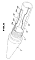
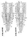
- Fig. 1 is a sectional view of a mechanical pencil according to a first embodiment of the present invention.
- the mechanical pencil has a tip member 2 attached to the front end of a shell 1 removably, a slider 3 received in the tip member 2 axially slidably, a sleeve 4 disposed in the tip member 2 axially slidably, a lead feed mechanism 5 mounted within the sleeve 4, a stopper 6 which is axially slidable through the interior of the rear portion of the sleeve 4, and a coupling 7 fitted and connected into the stopper 6.
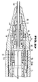
- the tip member 2 as shown in Figs. 1 to 3 and 5, has a fitting portion 21 for the shell 1 and a rear cylindrical portion 22 contiguous to the rear end of the fitting portion 21.
- the rear cylindrical portion as shown in Figs. 1 to 5, is formed with a pair of sliding slots 23 of a symmetric shape and slits 24 for ensuring radial elastic deformation of the rear cylindrical portion 22.
- the paired sliding slots 23, as shown in Figs. 1 to 5, are formed in an axially symmetric crank shape and each provided with a sleeve projection sliding slot 23a, for sliding therethrough of a later-described sleeve projection (sleeve engaging portion) 41, a stopper projection sliding slot 23b for sliding therethrough of a stopper projection 61, and a sleeve retreat restricting stepped portion 23c formed at the rear end of the sleeve projection sliding slot 23a.
- the sleeve retreat restricting stepped portion 23c functions to restrict a backward movement of the sleeve projection 41 moving backward in response to front-end knock or excess writing pressure damping action.
- a stopper lug retaining wall portion 23d formed at the rear end of the stopper projection sliding slot 23b functions to engage the stopper projection 61 and obtain a single unit-block of the tip member 2, sleeve 4 and coupling 7 which are each constructed as a block.
- annular slider receiving portion 8 is fitted in the front-side inner wall of the tip member 2, and inside the rear end of the slider receptable portion 8 there inwardly projects an annular slider stopper 81 which engages the slider 3 disengageably.
- the slider 3 as shown in Figs. 1 and 6 to 8, has a slider body 31, a slide pipe 32 fitted in the front end side of the slider body 31, and a symmetric, directionality-free, friction imparting member 33 fitted in the interior of the slider body 31 to impart a predetermined frictional force (e.g. 0.128-0.196N (13 - 20g)) to a lead S.
- the rear side of the slider 31 is formed with a plurality (four in this embodiment) of divided engaging pieces 34 which are engageable with the slider stopper 81 and capable of expanding and contracting in the diametrical direction.
- the engaging pieces 34 are each provided with an outwardly projecting engaging protuberance for engagement with and disengagement from the slider stopper 81.
- any one pair may be omitted.
- the upper half portion of the slider 3 and of a later-described ejection bar 10 in Fig. 1 [indicated at (i) in Fig. 1] shows a condition in the absence of any special external force such as when the pencil is not in use (hereinafter referred to as the "normal" condition), while the lower half portion [indicated at (ii) in Fig. 1] shows a later-described locked state.
- the sleeve 4 is disposed axially slidably within the tip member 2.
- the sleeve 4 is cylindrical and the outer periphery of its front side is formed with a pair of sleeve projections 41 for sliding through the sleeve projection sliding slot 23a, while on the rear side there are formed a pair of sliding slots 42 of the same shape which permits sliding therethrough of the stopper projections 61
- Each sliding slot 42 as shown in Figs. 9 and 10 has a guide slot 42a for guiding the stopper projection 61, and a frictional sliding slot 42b which is in communication with the guide slot 42a, with a frictional stepped portion 43 being formed intermediately of the frictional sliding slot 42b.
- the frictional stepped portion 43 functions to impart a frictional force to the stopper projection 61 and let the entire sleeve 4 advance a predetermined distance together with the stopper 6 to feed the lead S.
- the ejection bar 10 is connected to the front end of the sleeve 4 through a drum ring 9; the lead feed mechanism 5 is disposed in the interior of the sleeve; and at the rear end portion of the sleeve 4, the coupling 7 is engaged therewith and the axially slidable stopper 6 is disposed.
- the drum ring 9, which is fitted in the front end of the sleeve 4, 1 fulfils a guide function of internally holding the ejection bar 10 movably (slidably) in a predetermined range, 2 also functions to prevent drop-out of later-described balls 53 at a rear stepped portion 91.
- the reference numerals 93a and 93b shown on the front end side of the drum ring 9 each represent a retaining concave portion formed to retain a convex portion 104 of the ejection bar 10 movably with a predetermined engaging force as will be described later.
- the retaining concave portions 93a and 93b retain the ejection bar in the advanced position and retreated position, respectively.
- the ejection bar 10 held by the drum ring 9, as shown in Figs. 1 and 13, has a bar body 100, an axially extending cylindrical portion 101 centrally located in the interior of the bar body 100, a lead insertion hole 102 formed in the interior of the cylindrical portion 101, a retaining portion 103 for retaining the rear end of a later-described first resilient member 11, and the convex portion 104 which movably engages the retaining concave portions 93a and 93b of the drum ring 9.
- the engaging force between the retaining concave portion 93a on the front side (advanced position) of the drum ring 9 and the convex portion 104 is set at a value (e.g. 2.94 ⁇ 0.49N (300 g ⁇ 50 g)) larger than the engaging force (e.g. 0.981 ⁇ 0.294N (100 g ⁇ 30 g)) between the engaging protuberances 35 of the slider 3 and the slider stopper 81.
- a value e.g. 2.94 ⁇ 0.49N (300 g ⁇ 50 g)
- the engaging force e.g. 0.981 ⁇ 0.294N (100 g ⁇ 30 g)
- the first resilient member 11 (having a biasing force of say 0.098 - 0.118N (10 - 12 g)) is provided between the ejection lever 10 and the slider 3. It urges the slider 3 forward in the interior of the slider and outside the cylindrical portion 101 of the ejection bar 10, and at the same time it urges backward the ejection bar 10 and the sleeve 4 located therebehind.
- the cylindrical portion 101 of the ejection bar 10 extends long in the axial direction to cover the lead S in as large an area as possible, thereby preventing the breakage of the lead and also preventing the entry of lead waste or broken lead into a lead chuck 51. It further functions to retain the rear end of the lead feed mechanism 5 disposed within the sleeve 4.
- the lead feed mechanism 5 has a bisplit lead chuck 51, balls 53 held by a ball holding portion 52 at the head of the lead chuck 51, a metallic cylinder 54 adapted to be fitted as necessary into the front end portion of the sleeve 4 and having a tapered inner wall 54a for holding the balls 53 between it and the ball holding portion 52, and a second resilient member 56 for clamping the chuck, the second resilient member 56 being disposed between a stepped inner wall portion 44 of the sleeve 4 and a stepped retaining portion 55 of the lead chuck 51.
- the lead chuck 51 is formed of a forged or pressed sintered alloy, a molded metal obtained by die casting, or a synthetic resin molding obtained by compression molding.
- the lead chuck 51 is divided in two along the axis of a lead insertion hole 57 and comprises a pair of chuck members 51a and 51b each having a hemispheric section. And it has the ball holding portion 52, the stepped retaining portion 55 provided at the rear portion, a cylindrical rear tapered portion 58 extending backward from the rear end of the stepped retaining portion 55 so that it is smaller in diameter on the rear end side, the lead insertion hole extending along the axis, an engaging concave portion 59, an engaging convex portion 510, and an open/close fulcrum protuberance 511.
- the engaging concave and convex portions 59 and 510 are provided so that the engaging convex portion 510 of one chuck member 51a may be engaged with the engaging concave portion 59 of the other chuck member 51b and the engaging convex portion 510 of the other chuck member 51b may be engaged with the engaging concave portion 59 of one chuck member 51a, whereby the chuck members 51a and 51b are prevented from axial deviation from each.
- the engaging concave and convex portions 59 and 510 function as a fulcrum to bring the open/close fulcrum protuberances 511 of the chuck members 51a and 51b into abutment with each other and let the chuck members perform a lever motion in the opening and closing directions, and also function as a spacer for forming a sufficient gap K (see Fig. 1) to ensure a smooth lever motion.
- each engaging concave portion 510 in the radial direction of the lead insertion hole 57 is made larger by a distance corresponding to the distance of the open/close fulcrum protuberance 511, it is possible to omit the open/close fulcrum protuberances 511. Even in this case it is possible to attain the spacer function to form the gap K.
- lead holding holes 512 are provided on the front end side of the lead insertion hole 57 in the inner wall of the head portion of the lead chuck 51 .
- the lead holding holes 512 are semisplit holes formed centrally along the inner peripheral surfaces of the semisplit lead insertion holes 57 in the chuck members 51a and 51b. Their sectional shape is, for example, as shown in Figs. 17 to 20.
- the lead holding holes 512 are each formed in generally U shape in section larger in width on the chuck side for the lead S.
- the tooth portions 511 as shown in Figs. 18 to 20, are in a tapered form which is sharper on the front end side.
- Respective front end faces 511a are narrow flat faces and respective root portions 513 are also flat.
- the tooth portions 511 form lead support portions 514 which support the outer periphery of the lead S at four points in an integrally assembled state of the chuck members 51a and 51b.
- the lead support portions 514 formed by the tooth portions 511 afford a sufficient lead gripping force to hold the lead to an appropriate extent.
- the construction adopted permits the escape of dust, wastes and the like, e.g. lead wastes, so there is no fear of lead wastes being accumulated throughout the pencil. Even if lead wastes or the like begin to accumulate, they will be removed naturally with movement of the lead such as lead feed motion.
- chuck members 51a and 51b there are illustrated other examples of the chuck members 51a and 51b.
- tooth portions are formed projectingly only in the vicinity of the lead support portions 514.
- the lead holding holes 512 in Fig. 22 are formed in V shape in section.
- the lead holding holes 512 of the above examples may have other sectional shapes if only they can support the lead S at four points as described above.
- the balls 53 held by the head portion of the lead chuck 51, as shown in Fig. 1, are fitted in and held between the chuck head and the tapered inner wall 54a of the metallic cylinder 54 provided at the front end portion of the sleeve 4.
- the metallic cylinder 54 ensures positive, durable and stable rolling contact and positive lead holding performed by the lead chuck 51, and enhances durability.
- the metallic cylinder 54 is not always necessary. In normal use of the mechanical pencil, the metallic cylinder 54 may be omitted if the tapered inner wall 54a is formed at the inner surface of the front end of the sleeve 4 in the form of rolling contact with the balls 53.
- the lead chuck 51 illustrated is a bisplit chuck, it may be divided in three or more, or may be even a single body.
- the contact portion of the chuck members may be formed with engaging convex and concave or deviation preventing notches.
- a part of the diameter of the lead chuck 51 closely resembles the inside diameter of the sleeve 4, and the rear end of the second resilient member 56 is positively retained by the stepped retaining portion 55 of the lead chuck 51, so vertical and transverse fluttering motions and deviations of the lead chuck 51 are sure to be prevented.
- the ball holding portion 52 of the lead chuck 51 may be a mere hole for holding the balls 53, or it may receive the balls 53 therein to prevent drop-out of the balls.
- the balls 53 is rotatable in the ball holding portion 52.
- the second resilient member 56 has a biasing force weaker than that of the first resilient member 11.
- the stopper 6 provided on the rear end side of the sleeve 4 has a pair of upper and lower projections 61 as shown in Fig. 1 and it is fitted on the front end of the coupling 7 as previously noted.
- the stopper projections 61 fulfil the following functions. 1 It is retained in abutment with the stopper projection retaining wall 23d of the tip member 2 by a backward urging force of a third resilient member 12 to combine the tip member 2, the sleeve 4 and the coupling 7 which are constructed each in the form of a block, into one unit-block.
- the coupling 7 inserted in and engaged with the stopper 6 fulfils not only the function as a lead guide but also the function of connecting the lead pipe 13 removably. It has a lead feed hole 71 having an inside diameter which permits only one lead S to pass therethrough, a chuck receiving hole 72 formed contiguously to the rear end of the lead feed hole 71 and into which is removably inserted a chuck opening/closing mechanism 14 fitted in the front end of the lead pipe 13 in this embodiment, a stepped fitting hole 74 of a large diameter contiguous to the rear end of the chuck receiving hole 72 and into which is inserted the front end side of the lead pipe 13 removably, and an engaging projection 75 projecting from the inner wall of the fitting hole 74 to ensure the connection of the lead pipe 13.
- the front end of the lead pipe 13 is provided with the chuck opening/closing mechanism 14 as noted above.
- the chuck opening/closing mechanism 14 is described in detail in European Patent Application No. EP-A-0259120 already filed by the applicant in the present case.
- the third resilient member 12 fulfils 1 a forward returning function for the sleeve 4, the lead feed mechanism 5 and the ejection bar 10 at the time of front-end knock, 2 a backward returning function for the coupling 7 and the lead pipe 13 at the time of rear-end knock, and 3 an excess writing pressure damping function in writing. And it has a relatively strong biasing force (e.g. 3.63 - 3.92N (370 - 400 g )).
- the resilient member receiving portion 15 which receives the front end side of the third resilient member 12 comes into abutment on the front end side thereof with the rear end of the tip member 2 and that of the sleeve 4, whereby it is made possible for one third resilient member 12 to fulfil the above three functions.
- An urging force A of the first resilient member 11, a frictional force B of the friction imparting member 33 to the lead S, an engaging force C between the concave portion 93a of the drum ring 9 and the convex portion 104 of the ejection lever 10, an engaging force D between the slider 3 and the slider stopper 81, and a gripping force E of the lead chuck 51 for the lead S, are in the following relations:
- the lead feed mechanism 5 is mounted into the sleeve 4. More particularly, the chuck members 51a and 51b are assembled together and the second resilient member 56 is loosely fitted over the outer periphery of the assembled chuck.
- the metallic cylinder 54 is press-fitted beforehand along the inner wall of the front end portion of the sleeve 4. Then, the chuck members 51a and 51b with the second resilient member 56 loosely fitted thereon are inserted from the rear into the sleeve 4.
- the chuck members 51a and 51b are pressed from the rear to compress the second resilient member 56 and the balls 53 are inserted in the ball holding portion 52 of the chuck members 51a and 52b, followed by release of the pressure, whereby the balls 53 are sure to be set in the ball holding portion 52.
- the drum ring 9 is press-fitted into the front end of the sleeve 4.
- the ejection bar 10 with the first resilient member 11 engaged therewith is received beforehand into the drum ring 9.
- the sleeve 4, the lead feed mechanism 5, the drum ring 9, the ejection bar 10 and the first resilient member 11 are assembled as a block.
- the slider receiving portion 8 and the slider 3 are mounted and set beforehand into the tip member 2 to obtain a block of the tip member.
- the third resilient member 12 and the resilient member 15 are set to the coupling 7 and lastly the stopper 6 is brought into engagement with the same coupling to obtain a block. Urging force is exerted on the stopper 6 by virtue of the third resilient member 12 through the coupling fitted in the stopper and also through the resilient member receiving portion 15.
- the coupling 7 now available as a block is inserted from the rear end of the tip member 2 and that of the sleeve 4. This insertion is performed so that the stopper projections 61 of the stopper 6 on the front end side of the coupling 7 come into engagement with the interior of the sliding slots 23 of the tip member 2 and that of the sliding slots 42 of the sleeve 4.
- this unit block is inserted from the front end of the shell 1 and the lead pipe 13 inserted into the coupling 7 from the rear end of the shell. Now the assembly of the mechanical pencil is over.
- the lead feed operation can be performed by the following three methods.
- the above three types of lead feed operations can be performed.
- the sleeve 4 as a block, including the lead feed mechanism 5 which grips the lead S, and the resilient member receiving portion 15, are urged forward by the third resilient member 12. Therefore, if excess writing pressure should act on the lead S during writing, the sleeve 4 as a block and the resilient member receiving portion 15 retreat while compressing the third resilient member 12.
- this mechanical pencil has an excess writing pressure damping function.
- the rear end of the lead pipe 13 is knocked (in this case the lead chuck 51 opens to release the lead S and hence the sleeve 4 as a block is not in its rear position unlike the above front-end knock) and the slide pipe 32 is pressed against the surface of paper or the like, so that the slider 3 retreats while compressing the first resilient member 11. In the course of this backward movement, the rear end of the slider 3 pushes the ejection bar 10 backward.
- the pressing force of the slider 3 against the paper surface is larger than the engaging force between the convex portion 104 of the ejection bar 10 and the concave portion 93a of the drum ring 9, and the forward biasing force of the third resilient member 12 is larger than the said engaging force, so the ejection bar 10 alone is pushed backward and, as shown in Fig. 29, the convex portion 104 of the ejection bar 10 comes into engagement with the retreat-position retaining concave portion 93b of the drum ring 9 and is retained in its retreated position.
- the front end 104a of the convex portion of the ejection bar 10 is also pushed by the front end of the lead chuck 51 and is thereby moved forward to the concave portion 93a on the front side of the drum ring 9 as shown in Fig. 25.
- the ejection bar 10 is retained movably to the two predetermined positions of advanced and retreated positions by the two retaining concave portions 93a and 93b within the drum ring 9, and it is made slidable within the drum ring; further, three types of lead feed operations can be adopted and it is made possible to effect locked stow of the slider 3.
- the ejection bar 10 is fixed to the position of the advanced-position retaining concave portion 93a in the drum ring 9, or in this position the ejection bar 10 and the drum ring 9 are integrally formed. In this second embodiment, therefore, it is impossible to effect the locked stow of the slider 3, but the lead feed operation and other operations are just the same as in the first embodiment.
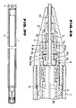
- Fig. 30 illustrates a third embodiment in which the coupling 7 and the lead pipe 13 are integrally formed.
- the chuck opening/closing mechanism 14 at the front end of the lead pipe 13 may be omitted and instead the front end of the lead pipe 13 may be removably attached to or press-fitted into the coupling 7 directly.
- the tip member 2 is formed as a bisplit body comprising a tip member body 2A and a connecting cylinder 2B.
- the connecting cylinder 2B is provided on the front end side thereof with a tip member connecting portion 21B1 and a shell connecting portion 21B2.
- Contiguous to the rear end of the shell connecting portion 21B2 is a rear cylindrical portion 22B having the same structure as the rear cylindrical portion 22 described in the embodiment of Fig. 1. That is, the rear cylindrical portion 22B has the paired sliding slots 23 and slits 24 shown in Figs. 1 to 5.
- the paired sliding slots 23 are each provided with a sleeve projection sliding slot 23a, a stopper projection sliding slot 23b and a sleeve retreat restricting stepped portion 23c.
- a slide tip 32A formed, for example, by turnery and having a diameter larger than that of the slide pipe 32 of the slider 3 shown in Fig. 1 is fitted in the front end of the slider body 31.
- the components of the mechanical pencil other than the shell are constructed in the unit of blocks whereby the assembling work, etc. can be simplified, the number of components required is reduced, and the components can be used efficiently for various purposes.
- the lead is covered with components such as the ejection bar at all times, it is possible to prevent breakage of the lead, etc. and attain the stabilization of quality.
- three types of lead feed operations can be done; the slider locking and stowing operation and the release of the locked stow can be effected easily; and there does not occur such an inconvenience as the lead being fed out inadvertently while one carries it with him.
- a friction imparting member 33 which constitutes a lead stopper is obtained by forming rubber or synthetic resin integrally into a cylindrical shape like known ones.
- the friction imparting member 33 has an annular recess 33A formed along the central part of its outer peripheral surface.
- the lead insertion hole 33B is coaxially formed with a front tapered hole 33C having a larger diameter on the front end side thereof and a rear tapered hole 33D having a larger diameter on the rear end side thereof.
- the front and rear ends on both sides of the recess 33A are of the same outside diameter, presenting a shape having no axial directionality.
- the friction imparting member 33 of the above construction can be formed easily because it has no directionality as mentioned above. Besides, it can be easily mounted into the mechanical pencil shown in Fig. 34 or 35.
- the friction imparting member 33 is press-fitted into the tip member 2 of the mechanical pencil, while in the case of Fig. 35, the friction imparting member 33 is press-fitted into the slider 3 which is axially slidable within the tip member 2.
- the friction imparting member 33 in the above assembled state can be deformed elastically in the diameter expanding direction through the recess 33A thereof, so its expansion which occurs upon insertion of the lead S into the lead insertion hole 33B due to axial and radial variations of the tip member 2 or the slider 3, variations in the lead diameter, or radial variations of the friction imparting member 33 itself, can be absorbed by elastic deformation in the diameter expanding direction of the recess 33A.
- the feed of lead is conducted automatically upon release of the writing pressure of the slider from the surface of paper or the like and, for such automatic lead feed upon release of the writing pressure, a lead gripping lead chuck permits easy advance of the lead but inhibits its retreat. Since friction imparting force of the friction imparting member for the lead during advance of the lead and that during retreat of the lead are different from each other, the feed of the lead can be effected smoothly and positively by using the above lead stopper as the friction imparting member.
- the lead stopper for imparting a predetermined frictional force to the lead to be fed out of the mechanical pencil is formed in a cylindrical shape having the same outside diameter throughout the overall length thereof, and a recess is formed along the central part of the outer peripheral surface of the lead stopper. Consequently, axial and radial variations of the tip member or the slider of the mechanical pencil attached to the lead stopper, as well as variations of the lead stopper itself, can be absorbed by the above recess. Besides, since the lead stopper has no directionality, it can be formed and mounted easily.
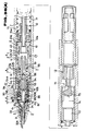
- Fig. 36 there is illustrated a mechanical pencil in section according to a sixth embodiment of the present invention. Portions different from the foregoing first embodiment will be explained.
- slider 3, drum ring 9 and ejection bar 10 are slightly different in construction from those described in the first embodiment.
- Figs. 37 to 39 illustrate a structure of the slider 3, in which the numeral 36 denotes an engaging recess which comes into engagement with a front-end engaging portion 96 (Fig. 40) of the drum ring 9 at the time of locking and stowing of the slider 3, and the numeral 36a denotes an inclined surface.
- the engaging recess 36 and the inclined surface 36a formed as portions of each engaging piece 34 of the slider 3.
- the drum ring 9 has a further function of receiving in its receptacle portion 9a the vicinity of the rear end of the slider 3 at the time of locking and stowing of the slider and engaging the slider through the engaging recesses 36.
- the numeral 94 denotes a stepped inner wall portion to restrict the backward movement of the ejection bar 10 and the numeral 95 denotes a front end wall portion.
- the front end wall portion 95 1 functions to push and abut the rear end of the slider 3 at the time of front-end knock to release the knock and 2 also functions to release the locked stowing of the slider 3.
- Numeral 96 represents the front-end engaging portion as referred to above.
- a distance e which corresponds to the lead feed quantity at the time of rear- and front-end knock as well as an automatic writing continuable distance.
- the ejection bar 10 as shown in Fig. 41, has an outer peripheral wall portion 104 received movably along the inner wall portion 93 of the drum ring 9, and a rear stepped portion 105 positioned behind the outer peripheral wall portion 104 and adapted to abut the stepped inner wall portion 94 of the drum ring 9 to restrict the backward movement, in addition to the bar body 100, cylindrical portion 101, lead insertion hole 102 and the retaining portion 103 which were explained in the first embodiment.
- Numeral 106 denotes a front end wall portion.
- the urging force A of the first resilient member 11, the frictional force B of the friction imparting member 33 to the lead S, and the gripping force C of the lead chuck 51 for the lead S are in the following relations.
- any one pair of two pairs of opposed engaging protuberances 35 may be omitted.
- the assembling operation for the mechanical pencil of this sixth embodiment is the same as that described in the first embodiment.
- the lead feed operation is also the same as in the first embodiment; that is, three types of lead feed operations can be performed which are rear-end knock, automatic lead feed by interruption of writing, and front-end knock.
- the rear-end knock is just the same as in the first embodiment, but the automatic lead feed as the second means and the front-end knock as the third means are performed at the front end of the drum ring 9 unlike the first embodiment, so this point will be explained below.
- the automatic lead feed operation which is performed by the interruption of writing, will first be explained.
- Writing is usually performed in a projecting state of the lead S by a predetermined amount X from the slide tip 32A, as shown in Fig. 42(A).
- the lead S wears little by little until it become flush with the front end of the slide tip 32A, as shown in Fig. 42(B).
- the slider 3 can retreat against the urging force of the first resilient member 11. Its maximum retreatable distance is up to abutment with the front end wall portion 95 of the drum ring 9, that is, up to the retreat distance e shown in Figs. 1, 42(B) and 42(C).
- Other operations are the same as in the first embodiment so will not be explained here.
- front-end knock as the third means whereby the front end of the slider 3 is pressed against the paper surface.
- front-end knock involves the following two cases, which are different in operation so will be explained separately.
- the engagement of the slider 3 with the slider receiving portion 8 is released by pressure abutment of the front end wall portion 95 of the drum ring 9 with the slider 3, so the front-end knock is ensured if slide pipe 32 is projecting from the tip member 2.
- this mechanical pencil has an excess writing pressure damping function like the first embodiment.
- the normal lead feed described above is performed by the above rear-end knock.
- the front end of the lead chuck 51 pushes the ejection bar 10, causing it to move forward.
- the slits 92 of the drum ring 9 are expanded to enlarge the opening area of the front end portion of the drum ring 9, thus affording a receptacle portion as a slider receiving space. Consequently, the vicinity of the rear end portion of the retreating slider 3 can be received smoothly into the receptacle portion 9a of the drum ring 9.
- the mechanical pencil of the present invention is also applicable as a mechanical pencil for drawing or a like purpose.
- the unlocking of the slider 3 and the release of the locked stow thereof at the time of front-end knock as well as the release of the engagement between the slider 3 and the slider receiving portion 8 are effected at the front end of the drum ring, so the front-end knock can be done positively as long as the slide pipe is projecting from the tip member.
- the opening of the drum ring 9 is expanded (opening/closing operation) with forward movement of the ejection bar 10 induced by rear-end knock to ensure a receptacle portion, thereby making it possible to lock and stow the slider 3.
- the drum ring 9 is formed not to perform opening/closing operation, thereby dispensing with the receptacle portion for the slider 3.
- this seventh embodiment therefore, it is quite impossible to effect locking and stowing of the slider 3.
- the other points, including the lead feed operation, are just the same as in the sixth embodiment.
- the drum ring 9 and the ejection bar 10 may be formed as an integral body.
- This embodiment concerns an improvement of the lead feed operations of rear-end knock, automatic writing and front-end knock, attained by modifying the elastic modulus of the first resilient member 11.
- Other constructional points are the same as in the foregoing seventh embodiment.
- the elastic modulus of the first resilient member 11 is determined so that the biasing force A of the resilient member 11 and the gripping force E of the lead chuck 51 for the lead S are in any of the following relationships:
- the writing is stopped when the retreat distance of the slider is f1 (f1 ⁇ f) and the tip end of the slide tip 32A is moved out of contact with the paper surface.
- the slider 3 stops in that position without operating at all.
- the slider tip 32A is brought into abutment with the paper surface to re-start the writing operation, the slider 3 moves back with wear of the lead S.
- the retreat distance of the slider 3 is f2 (f1 + f2 ⁇ f) , there exist the relationships 1 and 2 like the above case, so the slider 3 stops in that position.
- the first resilient member 11 causes the slider 3 to advance and at the same time the lead S is allowed to advance together with the slider 3 through a predetermined frictional force provided from the friction imparting member 33. In this way the lead is fed.
- the first resilient member 11 acts to advance the slider 3 and the lead S continually, so the lead feed operation is executed continually.
- the head portion of the lead chuck 51 is located a little ahead of its position shown in Fig. 42(B). Consequently, when backward writing pressure is exerted on the lead S upon re-start of writing, there are performed operations completely reverse to the lead drawing-out operations. More specifically, the lead chuck 51 which has gripped the lead S moves back in rolling contact with the tapered inner wall 54a and its inward contraction gives rise to a gradual increase of its lead gripping force until it returns to the position shown in Fig. 42(B), whereby there is effected complete lead gripping. Thus, the lead chuck 51 retreats upon re-start of automatic writing, so some users may feel a sense of incongruity or of discomfort. Besides, this retreat motion of the lead chuck 51 has heretofore occurred always at the time of start of automatic writing.
- the retreat distance of the lead chuck 51 is the same (f x ) as that of the lead S. And since there exists the relationship 3 as mentioned above, the slider 3 moves back the same distance (f x ) through the friction imparting member 33 which is in abutment with the lead S under the frictional force B. Therefore, if the writing is discontinued and the lead S is moved away from the paper surface, the slider 3 advances the distance f x under the biasing force of the first resilient member 11. As a result, as noted above, the lead chuck 51 is again moved forward and thereafter retreats a slight distance, but is located slightly ahead of its position shown in Fig. 42(A).
- this eighth embodiment as set forth above, by adjusting the elastic modulus of the first resilient member 11 it is made possible to feed the lead only when the retreat distance of the slider 3 reaches the predetermined distance or longer, and the occurrence of retreat motion of the lead chuck 51 is suppressed to a minimum degree to minimize the sense of incongruity or of discomfort at the time of start of writing. This is particularly effective in writing Japanese characters because the retreat distance of the slider 3 is in many cases below the distance f .
- the predetermined distance f at the start of lead feed is set at 0.5 mm, this constitutes no limitation if only it is within the distance b or e . Further, although the number of times of interruption of writing in automatic writing was set at twice or more, it may be even once.
- This embodiment relates to an improvement of the lead chuck.
- the greater part of its construction is the same as the preceding embodiments.
- the lead chuck 51 is formed as a bisplit chuck along the axis of the lead insertion hole 57 and it comprises a pair of chuck members 51a and 51b which are hemispheric in section.
- This bisplit lead chuck has ball holding portions 52 recessed in the outer peripheral portions of the chuck members 51a and 51b, retaining stepped portions 55 projecting from the said outer peripheral portions, spring retaining projections 55a projecting forward in predetermined positions from the front sides of the retaining stepped portions 55, stopper abutting projections 55b projecting backward in predetermined positions from the rear sides of the retaining stepped portions 55, rear cylindrical tapered portions 58 extending backward from the rear ends of the retaining stepped portions 55 and smaller in diameter on the rear end side, the lead insertion hole 57 extending through the axis of the lead chuck, engaging recesses 59 and engaging projections 510.
- the engaging projections 510 are formed longer by a predetermined length than the depth of the engaging recesses 59 to ensure a gap K between the lead chuck members 51a and 51b as shown in Figs. 43(A) and 47.
- the gap K functions as a fulcrum of lever motion of the chuck members 51a and 51b in opening and closing directions and also functions as a spacer to effect a smooth lever motion.
- the ball holding portions 52 each have a bank-like projecting portion 52a along the peripheral edge thereof as shown in Fig. 48 so that the ball 53 received therein may not easily escape outwardly sideways.
- the spring retaining projections 55a which are for retaining the rear end of the second resilient member 56, are projecting from the retaining stepped portions 55 in back positions of the chuck members 51a and 51b.
- the stopper abutting projections 55b function to abut the front end of the advancing stopper 6 to create a lead chuck opening force.
- a pair of such stopper abutting projections 55b are projecting from the retaining stepped portions 55 in both side positions of each of the chuck members 51a and 51b.
- the stopper abutting stepped portions 55b and the spring retaining projections 55a are provided in positions spaced about 90° from the axis of the lead insertion hole 57.
- an opening lever motion of the lead chuck 51 is performed smoothly and positively, as shown in Fig. 43(C), using the retaining recesses 59 and the engaging projections 510 as a fulcrum, by the stopper abutting projections 55b which receive a forward urging force from the advancing stopper 6 at the time of rear-end knock and also by the spring retaining projections 55a which receive an opposite external force, i.e., a backward urging force, from the thereby-compressed second resilient member 56.
- the lever opening motion of the lead chuck 51 can be effected without utilizing the taper means at the rear ends of the lead chuck members 51a and 51b. Besides, there is no fear of deviation at the heads of the lead chuck members 51a and 51b.
- the distance between the stopper abutting projections 55b and the spring retaining projections 55a and their positions are not restricted to those in this embodiment. Any such distance and positions may be adopted if only there can be developed a force which induces the opening lever motion of the lead chuck 5.
- the inner surfaces of both sides of a lead holding hole 512 serve as lead supporting portions 513.
- the lead supporting portions 513 are in four positions in the case of a four-point support type tooth portion 511a shown in Fig. 51.
- the lead support portions are in four positions initially, but as the lead S becomes finer, bottom portions 512a of the lead holding hole 512 also serve as lead supporting portions, that is, the lead is supported at six points.
- the lead supporting portions 513 are each integrally formed with a plurality of tooth portions 511 at predetermined intervals in the width direction of the lead supporting portion.
- Fig. 51 shows an example of the tooth portion 511 of the chuck members 51a and 51b.
- the tooth portion 511 is formed by only the four-point support type tooth portion 511 shown in Fig. 50.
- the four-point support type tooth portion 511a is formed from a plane portion 51a1 or 51b1 of the chuck member 51a or 51b up to a side wall 512b of the lead holding hole 512, except the bottom portions 512a of the lead holding hole 512. In the portion of each bottom 512a having no tooth there is formed a lead waste discharge portion 512c.
- the lead S is four-point supported by the tooth portions 511a in the positions of the lead supporting portions 513 which are formed at four points as shown in Fig. 49, so there is no fear of lead slip, etc.
- Fig. 52 shows another example of the tooth portion 511.
- the tooth portion 55 is formed by only the six-point support type tooth portion 511b shown in Fig. 49.
- the six-point support type tooth portion 511b is different from the four-point support type tooth portion 511a in that the lead waste discharge portion 512c is not present and so tooth portion is formed continuously from the plane portion 51a1 or 51b1 up to the lead holding hole 512.
- the lead S is initially gripped in the four-point support positions of the lead supporting portions 513.
- the lead S in the gripping portion becomes finer as indicated by dotted lines (X) in Fig. 49.
- the portions of the lead S indicated at (Y) are newly gripped by bottom portions 511b1 of the six-point support type tooth portions and thus supported at six points.
- This six-point support for the lead S further reduces the possibility of lead slip, etc. as compared with the first example.
- Fig. 53 shows a further example of the tooth portion 511.
- the tooth portion 511 comprises the four-point support type tooth portion 511a and the six-point support type tooth portion 511b, arranged in positions adjacent to each other alternately.
- the lead S is initially four-point supported by the four-point support type tooth portions 511a and the six-point support type tooth portions 511b. Thereafter, as the lead S becomes finer over a long period of use as mentioned above, it is supported at six points by the six-point support type tooth portions 511b. In this case, the lead S is four-point supported by the four-point support type tooth portions 511a and six-point supported by the six-point support type tooth portions 511b, and this supported state is repeated alternately in plural number of times.
- the lead S is gripped securely even under changes of its diameter by the two kinds of tooth portions 511a and 511b, so there is no fear of lead slip, etc.
- a cylindrical front-end portion 62 On the front end side of the stopper 6 there extends a cylindrical front-end portion 62 axially forwardly as shown in Figs. 43(A) and (C). At the time of rear-end knock, the front end of the cylindrical front-end portion 62 comes into pressure abutment with the stopper abutting projections 55b to open the lead chuck 51 in cooperation with the spring retaining projections 55a which are urged backward by the second resilient member 56. As shown in Fig.
- the urging force A of the first resilient member 11, the frictional force B of the friction imparting member 33 to the lead S, and the gripping force C of the lead chuck 51 for the lead S, are in the following relations.
- the spring retaining projections and the stopper abutting projections which undergo opposite external forces at the time of rear-end knock, are formed on the retaining stepped portion in spaced relation by a predetermined distance and an opening lever motion is created by utilizing opposite interactive forces to open the lead chuck. Consequently, there is no fear of deviation, etc. at the front end portion of the lead chuck, so it is possible to effect the lead releasing operation always in a stable state and the slip and breakage of lead caused by deviation at the front end of the lead chuck can be decreased remarkably.
Landscapes
- Mechanical Pencils And Projecting And Retracting Systems Therefor, And Multi-System Writing Instruments (AREA)
Claims (3)
- Porte-mine comprenant :
un élément de pointe (2) monté de façon amovible dans l'extrémité avant d'une coque (1);
un manchon (4) disposé de manière à pouvoir glisser à l'intérieur dudit élément de pointe (2) ; et
un mécanisme (5) d'alimentation de mine, qui est monté à l'intérieur dudit manchon (4) et permet un mouvement d'avance d'une mine, mais empêche un mouvement de recul de cette dernière;
caractérisé par
une barre d'éjection (10) montée sur le côté d'extrémité avant dudit manchon (4), la mine traversant l'intérieur de la barre d'éjection (10);
un tambour cylindrique (9) disposé sur le côté d'extrémité avant dudit manchon (4), ladite barre d'éjection (10) étant disposée de manière à pouvoir glisser dans ledit tambour cylindrique (9) de telle sorte que ce dernier assume une fonction de guidage pour retenir ladite barre d'éjection (10) dans une position prédéterminée et l'amener à glisser sur une distance prédéterminée;
un coulisseau (3) disposé de manière à pouvoir glisser dans ledit élément de pointe (2) et possédant une partie d'engagement avec blocage (34) apte à s'engager de façon amovible avec ledit élément de pointe (2), ledit coulisseau (3) appliquant une force de frottement prédéterminée à la mine; et
un élément élastique (11) disposé entre ledit coulisseau (3) et ladite barre d'éjection (10), ledit élément élastique (11) ayant à tout moment une force de sollicitation supérieure à une force de saisie de la mine par ledit mécanisme (5) d'avance de la mine. - Porte-mine selon la revendication 1, dans lequel ladite barre d'éjection (10) pousse ledit coulisseau (3) dans un état bloqué de manière à déverrouiller le coulisseau (3) lorsque la barre d'éjection (10) est retenue dans une position avancée à l'intérieur dudit tambour cylindrique (9), et supprime un état bloqué et enclenché du coulisseau (3) lorsque la barre d'éjection (10) avance à l'intérieur au tambour cylindrique (9) au moment d'un choc appliqué à son extrémité arrière.
- Porte-mine selon la revendication 1, dans lequel ledit tambour cylindrique (9) fournit une partie formant logement pour ledit coulisseau (3) lors d'un déplacement de ladite barre d'éjection (10) vers l'arrière.
Applications Claiming Priority (12)
| Application Number | Priority Date | Filing Date | Title |
|---|---|---|---|
| JP62094905A JPS63260493A (ja) | 1987-04-17 | 1987-04-17 | シヤ−プペンシル |
| JP94905/87 | 1987-04-17 | ||
| JP1987067103U JPH0545515Y2 (fr) | 1987-05-02 | 1987-05-02 | |
| JP67101/87U | 1987-05-02 | ||
| JP67102/87U | 1987-05-02 | ||
| JP1987067102U JPS63176685U (fr) | 1987-05-02 | 1987-05-02 | |
| JP1987067101U JPS63176683U (fr) | 1987-05-02 | 1987-05-02 | |
| JP67103/87U | 1987-05-02 | ||
| JP155777/87 | 1987-06-23 | ||
| JP62155777A JP2554260B2 (ja) | 1987-06-23 | 1987-06-23 | シヤ−プペンシル |
| JP145438/87U | 1987-09-25 | ||
| JP1987145438U JPS6450990U (fr) | 1987-09-25 | 1987-09-25 |
Publications (2)
| Publication Number | Publication Date |
|---|---|
| EP0287237A1 EP0287237A1 (fr) | 1988-10-19 |
| EP0287237B1 true EP0287237B1 (fr) | 1992-05-13 |
Family
ID=27551060
Family Applications (1)
| Application Number | Title | Priority Date | Filing Date |
|---|---|---|---|
| EP88302789A Expired EP0287237B1 (fr) | 1987-04-17 | 1988-03-29 | Porte-mine |
Country Status (4)
| Country | Link |
|---|---|
| US (1) | US4884910A (fr) |
| EP (1) | EP0287237B1 (fr) |
| DE (1) | DE3870973D1 (fr) |
| ES (1) | ES2033427T3 (fr) |
Cited By (1)
| Publication number | Priority date | Publication date | Assignee | Title |
|---|---|---|---|---|
| USD712481S1 (en) | 2013-03-15 | 2014-09-02 | Sanford, L.P. | Mechanical pencil |
Families Citing this family (10)
| Publication number | Priority date | Publication date | Assignee | Title |
|---|---|---|---|---|
| JP2585911Y2 (ja) * | 1993-04-12 | 1998-11-25 | 株式会社壽 | 棒状物繰り出し容器 |
| US5462376A (en) * | 1994-02-16 | 1995-10-31 | Kotobuki & Co., Ltd. | Mechanical pencil with improved slider mechanism |
| DE19502779C5 (de) * | 1994-03-26 | 2007-08-30 | Faber-Castell Ag | Druckbleistift |
| JP3466739B2 (ja) * | 1994-10-28 | 2003-11-17 | 株式会社壽 | シャープペンシルのスライダ |
| US5555602A (en) * | 1994-12-14 | 1996-09-17 | Leamond; William T. | Eraser assembly |
| JP3323022B2 (ja) * | 1995-01-19 | 2002-09-09 | 株式会社壽 | シャープペンシル |
| FR2866598B1 (fr) * | 2004-02-24 | 2008-04-04 | Bic Soc | Porte-mine a guide mine retractable |
| JP4847487B2 (ja) * | 2008-03-26 | 2011-12-28 | 三菱鉛筆株式会社 | シャープペンシル |
| JP5996219B2 (ja) * | 2012-03-07 | 2016-09-21 | 三菱鉛筆株式会社 | シャープペンシル |
| CN102815130B (zh) * | 2012-09-11 | 2015-01-07 | 张宜德 | 前端揿动出芯式自动铅笔 |
Family Cites Families (10)
| Publication number | Priority date | Publication date | Assignee | Title |
|---|---|---|---|---|
| DE2153400A1 (de) * | 1971-10-27 | 1973-05-03 | Kemal Dipl Ing Butka | Fuellstifte fuer duenne bleiminen |
| DE3112869A1 (de) * | 1980-03-31 | 1982-02-04 | Pentel K.K., Tokyo | "minenschreibermechanik" |
| DE3032200C2 (de) * | 1980-08-27 | 1982-11-25 | Fa. J.S. Staedtler, 8500 Nürnberg | Füllbleistift mit beim Schreiben selbsttätig erfolgendem Minenvorschub |
| JPS57189898A (en) * | 1981-05-19 | 1982-11-22 | Sakura Color Prod Corp | Note |
| EP0146128A3 (fr) * | 1983-12-15 | 1985-07-24 | Micro Co., Ltd. | Porte-mine automatique |
| US4650359A (en) * | 1984-04-27 | 1987-03-17 | Pentel Kabushiki Kaisha | Mechanical pencil with automatic lead advance |
| DE3670598D1 (de) * | 1985-01-26 | 1990-05-31 | Kotobuki & Co Ltd | Immer scharfer bleistift. |
| JPS6218296A (ja) * | 1985-07-18 | 1987-01-27 | ミクロ株式会社 | シヤ−プペンシル |
| DE3668140D1 (de) * | 1985-08-20 | 1990-02-15 | Kotobuki & Co Ltd | Minenvorschubmechanismus fuer fuellminenstift. |
| US4872776A (en) * | 1986-10-30 | 1989-10-10 | Kotobuki & Co., Ltd. | Lead chuck of mechanical pencil |
-
1988
- 1988-03-22 US US07/171,881 patent/US4884910A/en not_active Expired - Lifetime
- 1988-03-29 ES ES198888302789T patent/ES2033427T3/es not_active Expired - Lifetime
- 1988-03-29 DE DE8888302789T patent/DE3870973D1/de not_active Expired - Lifetime
- 1988-03-29 EP EP88302789A patent/EP0287237B1/fr not_active Expired
Cited By (1)
| Publication number | Priority date | Publication date | Assignee | Title |
|---|---|---|---|---|
| USD712481S1 (en) | 2013-03-15 | 2014-09-02 | Sanford, L.P. | Mechanical pencil |
Also Published As
| Publication number | Publication date |
|---|---|
| EP0287237A1 (fr) | 1988-10-19 |
| ES2033427T3 (es) | 1993-03-16 |
| US4884910A (en) | 1989-12-05 |
| DE3870973D1 (de) | 1992-06-17 |
Similar Documents
| Publication | Publication Date | Title |
|---|---|---|
| EP0287237B1 (fr) | Porte-mine | |
| US5074694A (en) | Latch mechanism for retractable writing instruments | |
| US4872776A (en) | Lead chuck of mechanical pencil | |
| EP0315337B1 (fr) | Porte-mine | |
| US4896982A (en) | Lead feed mechanism for mechanical pencil | |
| KR910002705Y1 (ko) | 샤아프펜슬 | |
| KR900005504B1 (ko) | 샤아프 펜슬 | |
| KR900004444Y1 (ko) | 샤아프펜슬의 돌출바아 | |
| JPH0545515Y2 (fr) | ||
| JPH02122996A (ja) | シャープペンシルの芯送出機構およびその組立方法 | |
| JPH0615735Y2 (ja) | ノック式筆記具 | |
| JPH0617588Y2 (ja) | シャープペンシルのリードチャック | |
| KR900004447Y1 (ko) | 샤아프펜슬 | |
| JPH052517B2 (fr) | ||
| KR19980032026A (ko) | 측방녹크식 샤아프펜슬 | |
| KR900006766Y1 (ko) | 샤아프펜슬의 리이드척 | |
| KR910000328Y1 (ko) | 샤아프펜슬 | |
| KR910005295Y1 (ko) | 샤아프펜슬의 리이드척 | |
| MXPA06004495A (es) | Lapicero. | |
| JPH0453980Y2 (fr) | ||
| KR910005222B1 (ko) | 샤아프펜슬의 필심송출기구 | |
| JPS63281898A (ja) | シヤ−プペンシル | |
| JP3856548B2 (ja) | 複合繰り出し用具 | |
| KR910007433Y1 (ko) | 샤아프펜슬의 리이드척 | |
| KR890001642B1 (ko) | 샤아프 펜슬 |
Legal Events
| Date | Code | Title | Description |
|---|---|---|---|
| PUAI | Public reference made under article 153(3) epc to a published international application that has entered the european phase |
Free format text: ORIGINAL CODE: 0009012 |
|
| AK | Designated contracting states |
Kind code of ref document: A1 Designated state(s): DE ES FR GB IT |
|
| 17P | Request for examination filed |
Effective date: 19881124 |
|
| 17Q | First examination report despatched |
Effective date: 19900502 |
|
| GRAA | (expected) grant |
Free format text: ORIGINAL CODE: 0009210 |
|
| AK | Designated contracting states |
Kind code of ref document: B1 Designated state(s): DE ES FR GB IT |
|
| REF | Corresponds to: |
Ref document number: 3870973 Country of ref document: DE Date of ref document: 19920617 |
|
| ET | Fr: translation filed | ||
| ITF | It: translation for a ep patent filed | ||
| REG | Reference to a national code |
Ref country code: ES Ref legal event code: FG2A Ref document number: 2033427 Country of ref document: ES Kind code of ref document: T3 |
|
| PLBE | No opposition filed within time limit |
Free format text: ORIGINAL CODE: 0009261 |
|
| STAA | Information on the status of an ep patent application or granted ep patent |
Free format text: STATUS: NO OPPOSITION FILED WITHIN TIME LIMIT |
|
| 26N | No opposition filed | ||
| PGFP | Annual fee paid to national office [announced via postgrant information from national office to epo] |
Ref country code: GB Payment date: 19940321 Year of fee payment: 7 |
|
| PGFP | Annual fee paid to national office [announced via postgrant information from national office to epo] |
Ref country code: ES Payment date: 19940329 Year of fee payment: 7 |
|
| PG25 | Lapsed in a contracting state [announced via postgrant information from national office to epo] |
Ref country code: GB Effective date: 19950329 |
|
| PG25 | Lapsed in a contracting state [announced via postgrant information from national office to epo] |
Ref country code: ES Free format text: LAPSE BECAUSE OF NON-PAYMENT OF DUE FEES Effective date: 19950330 |
|
| GBPC | Gb: european patent ceased through non-payment of renewal fee |
Effective date: 19950329 |
|
| PGFP | Annual fee paid to national office [announced via postgrant information from national office to epo] |
Ref country code: FR Payment date: 19980310 Year of fee payment: 11 |
|
| REG | Reference to a national code |
Ref country code: ES Ref legal event code: FD2A Effective date: 19990405 |
|
| PG25 | Lapsed in a contracting state [announced via postgrant information from national office to epo] |
Ref country code: FR Free format text: LAPSE BECAUSE OF NON-PAYMENT OF DUE FEES Effective date: 19991130 |
|
| REG | Reference to a national code |
Ref country code: FR Ref legal event code: ST |
|
| PGFP | Annual fee paid to national office [announced via postgrant information from national office to epo] |
Ref country code: DE Payment date: 20010319 Year of fee payment: 14 |
|
| PG25 | Lapsed in a contracting state [announced via postgrant information from national office to epo] |
Ref country code: DE Free format text: LAPSE BECAUSE OF NON-PAYMENT OF DUE FEES Effective date: 20021001 |
|
| PG25 | Lapsed in a contracting state [announced via postgrant information from national office to epo] |
Ref country code: IT Free format text: LAPSE BECAUSE OF NON-PAYMENT OF DUE FEES;WARNING: LAPSES OF ITALIAN PATENTS WITH EFFECTIVE DATE BEFORE 2007 MAY HAVE OCCURRED AT ANY TIME BEFORE 2007. THE CORRECT EFFECTIVE DATE MAY BE DIFFERENT FROM THE ONE RECORDED. Effective date: 20050329 |