EP0287255A2 - Bande conductrice réglable - Google Patents
Bande conductrice réglable Download PDFInfo
- Publication number
- EP0287255A2 EP0287255A2 EP88302990A EP88302990A EP0287255A2 EP 0287255 A2 EP0287255 A2 EP 0287255A2 EP 88302990 A EP88302990 A EP 88302990A EP 88302990 A EP88302990 A EP 88302990A EP 0287255 A2 EP0287255 A2 EP 0287255A2
- Authority
- EP
- European Patent Office
- Prior art keywords
- strip
- spikes
- mechanical connector
- adjustable
- body strap
- Prior art date
- Legal status (The legal status is an assumption and is not a legal conclusion. Google has not performed a legal analysis and makes no representation as to the accuracy of the status listed.)
- Granted
Links
Images


Classifications
-
- A—HUMAN NECESSITIES
- A61—MEDICAL OR VETERINARY SCIENCE; HYGIENE
- A61N—ELECTROTHERAPY; MAGNETOTHERAPY; RADIATION THERAPY; ULTRASOUND THERAPY
- A61N1/00—Electrotherapy; Circuits therefor
- A61N1/14—Leading-off electric charges, e.g. by earthing
-
- Y—GENERAL TAGGING OF NEW TECHNOLOGICAL DEVELOPMENTS; GENERAL TAGGING OF CROSS-SECTIONAL TECHNOLOGIES SPANNING OVER SEVERAL SECTIONS OF THE IPC; TECHNICAL SUBJECTS COVERED BY FORMER USPC CROSS-REFERENCE ART COLLECTIONS [XRACs] AND DIGESTS
- Y10—TECHNICAL SUBJECTS COVERED BY FORMER USPC
- Y10T—TECHNICAL SUBJECTS COVERED BY FORMER US CLASSIFICATION
- Y10T24/00—Buckles, buttons, clasps, etc.
- Y10T24/40—Buckles
- Y10T24/4088—One-piece
-
- Y—GENERAL TAGGING OF NEW TECHNOLOGICAL DEVELOPMENTS; GENERAL TAGGING OF CROSS-SECTIONAL TECHNOLOGIES SPANNING OVER SEVERAL SECTIONS OF THE IPC; TECHNICAL SUBJECTS COVERED BY FORMER USPC CROSS-REFERENCE ART COLLECTIONS [XRACs] AND DIGESTS
- Y10—TECHNICAL SUBJECTS COVERED BY FORMER USPC
- Y10T—TECHNICAL SUBJECTS COVERED BY FORMER US CLASSIFICATION
- Y10T24/00—Buckles, buttons, clasps, etc.
- Y10T24/44—Clasp, clip, support-clamp, or required component thereof
- Y10T24/44291—Clasp, clip, support-clamp, or required component thereof including pivoted gripping member
- Y10T24/44547—Clasp, clip, support-clamp, or required component thereof including pivoted gripping member having inserted and receiving interlocking engaging faces
Definitions
- the present invention relates generally to electrically conductive body straps and more particularly to electrically conductive body straps which are adjustable.
- the buildup of electrostatic charges and their subsequent discharge is a significant problem in certain industries. Individuals working in an everyday work environment commonly may develop thousands of volts of electrostatic charge potential by, as an example, walking across carpeting or moving dissimilar objects against each other. An individual, or object, so charged presents a severe hazard in certain environments. One example is an explosive environment where the danger is inherently obvious. Another example is the electronic integrated circuit (component) industry.
- the charged individual or object may discharge near or through an electrostatic sensitive electronic component. For example, an individual who is electrostatically charged may hold an electrostatic sensitive component and then lay the component on a surface, e.g., a grounded work surface, at a different potential from the the individual.
- a device which is used to help control the electrostatic charge buildup on a person is a body strap or wrist strap to be worn by the individual.
- the body straps are conductive on the surface contacting the skin surface and provide for an electrical connection point.
- An electrical ground cord may then be connected to the strap connecting the strap to an electrical ground potential, preferably through a predetermined limiting resistance usually built into the connector or the cord itself. So connected, such a body strap operates by draining any accumulated electrostatic charge on the individual to ground before the electrostatic charge buildup reaches dangerous levels.
- Christiansen et al describes a body strap which is constructed from a band of fabric formed into a closed loop to encircle a body part, e.g., wrist, to which it is to be connected.
- the fabric is electrically conductive on the interior surface of the closed loop contacting the skin.
- a mechanical connection mechanism holds the loop of fabric in a fixed predetermined size.
- An electrical connection mechanism provides for an electrical connection between the conductive inner surface of the fabric to an electrical grounding cord which may be attached to the strap.
- the fabric is elastomeric to enable the body strap to expand to slip over the hand and still be snug around the wrist.
- the opposite ends of the fabric are permanently secured in the mechanical connector.
- the body of the connector has projections which grip the fabric and hold the fabric in the connector when the cover is secured.
- the resultant body strap formed is a fixed closed loop size. Since the fabric has a limit on the degree of its elastic nature, a range of sizes of closed loops for the body strap must be provided. This results in the necessity of stocking a plurality of differing sizes of body straps.
- the elastomeric characteristics of the fabric generally means a fixed "life" of use of the fabric before its elastomeric or electroconductivity characteristics begin to break down. Since the fabric is secured in the connector at the factory, the replacement of the fabric requires replacement of the entire body strap.
- the Charge-Guard 2200 series of static control wrist straps manufactured by Minnesota Mining and Manufacturing Company, St. Paul, Minnesota and marketed by Static Control Systems/3m, Austin, Texas is constructed generally as described in Christiansen et al (Charge-Guard is a registered trademark of Minnesota Mining and Manufacturing Company, St. Paul, Minnesota).
- the ends of the projections 32, in Christiansen et al are sonically welded after the fabric is in place to "mushroom" the ends of the projections in order to ensure that the fabric is secured in the connector.
- U.S. Patent No. 4,577,256, Breidegam, Woven Stretchable Grounding Strap describes a wrist strap designed to be used to control electrostatic charge accumulations.
- the Breidegam strap has a clasp which allows its size to be adjusted.
- the adjustable clasp avoids the need to manufacture two or more models of the strap for different sized wrists. This does require that the strap be individually adjusted to fit snugly around the wrist of the individual wearer. If inadvertently or intentionally maladjusted, proper electrostatic protection may not be achieved.
- one end of the fabric is permanently secured into the clasp and held by plate and a rivet. Thus, one end of the fabric is fixed at the factory for the entire life of the strap.
- a pivotally mounted gate which when closed “jams” the fabric holding it in place, optionally with teeth to help the securing of the fabric.
- a pivotally mounted "jam” or “wedge” as is described in Breidegam is referred to as an "over-center” device. These devices operate by wedging the fabric between the jam member and a reaction member by using an eccentric pivot with a relatively long jam operating lever to gain the necessary leverage for the jam to work.
- One problem in a strap as described in Breidegam is that it does not allow for full 360 degree electrical contact with the skin and the fabric is electrically only connected at one end.
- any charge contacting the inner surface of the fabric must travel around the strap in one direction only until reaching the fixed end. This requires, in some instances, a charge must follow only one path to travel almost entirely around the fabric before being connected to a ground strap. Since the electrical conductivity of the fabric, due to its elasticity, is typically the weakest link in a wrist strap grounding system, along with the fabric to skin contact, such one way only conductivity is a serious problem. Another problem with the Breidegam strap is that the pivotally mounted gate does not lend itself to economical manufacture. Because of the forces involved, the pivot points are required to be quite sturdily built.
- the present invention provides a body or wrist strap useful for the control of electrostatic charge accumulation.
- the body strap provides adjustability without the use of expensive "over-center” jam mechanisms.
- the body strap provides for full 360 degree electrical contact with the skin and two parallel paths to ground, provides easy one-time, or repeated, adjustment by the individual user, for trouble free secure holding of the fabric ends and for the replacability of the fabric only, if desired.
- the present invention provides for an adjustable, conductive body strap.
- the strap has a strip of material having a first end and a second end with the strip of material being electrically conductive on at least one surface, being elastomerically extensible in its longitudinal direction and being of at least a length to enable the strip of material to encircle a body part.
- a mechanical connector receives the first end and the second end of the strip of material to form a closed loop with the strip of material with the conductive surface formed toward the interior of the closed loop.
- the mechanical connector has a first part receiving the first end of the strip material and has a second part receiving the second end of the strip of material.
- the first part of the mechanical connector has a recess which receives the first end of the strip material the recess being formed with a plurality of spikes upon which the strip of material is impaled and secured.
- the second part of the mechanical connector has a transverse bar around which the second end of the strip of material is passed passing firstly the interior of the transverse bar and secondly exterior of the transverse bar.
- the transverse bar has a plurality of spikes mounted on its exterior surface upon which the strip of material may be impaled after the strip of material has been pulled tight around the body part.
- the second part of the mechanical connector further has a hinged cover for being secured over the spikes of the transverse bar trapping the strip of material thereon.
- An electrical connection mechanism is coupled to the strip of material for making electrical contact with the interior conductive surface and for providing a connection point for an electrical cable capable of connecting the conductive body strap to ground.
- the hinged cover is releasably secured over the spikes.
- the connector has a second cover secured to the first part of the mechanical connector securing the first end of the strip of material on the spikes.
- the second cover is semi-permanently attached to the first part of the mechanical connector.
- the second cover is electrically conductive on its side which faces the strip of material.
- the second cover also contacts the second end of the strip of material providing full 360 degree electrical continuity.
- the hinged cover has transverse ridges spaced to pass on either side of the transverse bar when the hinged cover is closed.
- the transverse ridges force the strip of material into electrical contact with the second cover when the hinged cover is closed.
- the hinged cover has a plurality of recesses receiving the tip of each of the spikes mounted on the transverse bar.
- the spikes have a zero draft profile facing the direction toward the second end of the strip of material.
- the spikes are angled toward the second end of the strip of material.
- the hinged cover of the mechanical connector is hingably attached at one side and, preferably, secured by means of a hook.
- the hinged cover is releasably secured in a closed position by a flexible hook.
- the electrical connection mechanism and the mechanical connection mechanism operate in conjunction with each other by means of the metallic plate secured by means of metallic stud formed to receive a snap connector.
- the metallic stud maybe threaded and secured with a cooperating threaded member.
- the second part of the mechanical connector has a plate over which the second end of the strip of material is passed.
- the plate has a plurality of spikes mounted on its surface upon which the strip of material may be impaled after the strip of material has been pulled to fit snugly around the body part.
- This second part of the mechanical connector further has a hinged cover which may be secured over the spikes of the plate trapping the strip of material thereon.
- An electrical connection mechanism is coupled to the strip of material for providing a connection point for an electrical cable capable of connecting the conductive body strap to ground.
- the body strap further has a second cover secured to the first part of the mechanical connector securing the first end of the strip of material upon the spikes.
- the second cover, back plate is electrically conductive on its side which faces the strip of material.
- the second cover also contacts the second end of the strip of material providing full 360 degree electrical continuity and full 360 degree electrical contact with the skin.
- the hinged cover has transverse ridges spaced to pass on either side of the plate when the hinge cover is closed.
- the transverse ridges force the strip of material into electrical contact with the second cover when the hinged cover is closed.
- the hinged cover has a plurality of recesses receiving the tip of each of the spikes mounted on the plate.
- the spikes have a zero draft profile facing the direction toward the second end of the strip of material.
- the spikes are angled toward the second end of the strip of material.
- the hinged cover of the mechanical connector is hingably attached at one side and, preferably, secured by means of a hook.
- the hinged cover is releasably secured in a closed position by flexible hook, preferably opposite the hinge.
- the electrical connection mechanism and the mechanical connection mechanism operate in conjunction with each other by means of the metallic plate, second cover, secured by means of a metallic stud formed to receive a snap connector.
- the metallic stud may be threaded and secured with a cooperating threaded member.
- the electrically conductive inner piece has a slot through which the second end of the strip of material is passed.
- the strap further has an adjustment mechanism secured to the second end of the strip of material and to the strip of material intermediate the mechanical connector for adjustably holding the strip of material in the closed loop.
- the body strap further has an electrical connection mechanism coupled to the strip of material for making electrical contact with the at least one conductive surface and for providing a connection point for an electrical cable capable of connecting the conductive body strap to ground.
- the electrically conductive inner piece makes electrical contact with the at least one surface of the first end of the strip of material and also makes electrical contact with the at least one surface of the strip of material where the strip of material passes through the slot in the electrically conductive inner piece providing 360 degree electrical continuity.
- the adjustment mechanism comprises an eight-ring.
- the inner piece of the mechanical connector is a metallic plate and is secured by means of a metallic stud formed to receive a snap connector the metallic plate and the metallic stud forming the electrical connection mechanism.
- the adjustable, electrically conductive body strap 10 is illustrated in Figure 1.
- the body strap 10 is formed into a closed loop designed to fit snugly around a portion of the body, e.g., a wrist or an ankle.
- the loop is formed by a strip of material 12 formed into a loop by connector 14.
- Connector 14 forms both the mechanical connection holding both ends of the strip of material 12 and the electrical connection mechanism providing a point for external connection of the body strap 10 to a ground potential.
- the interior surface 16 of the strip of material 12 is electrically conductive and should intimately contact the skin of the individual wearer of the body strap 10 when it is in position.
- Strip of material 12 may be formed of any suitable elastomeric electrically conductive material such as a fabric to form the band portion of the body strap 10.
- strip of material 12 is a knit fabric containing both elastomeric and electrically conductive fibers as described in Christiansen et al.
- strip of material 12 could also be constructed from a stretch weave material such as is described in Breidegam.
- a first end 20 of the strip of material 12 is mechanically secured in a first part 22 of connector 14.
- the second end 24 of the strip of material 12 is adjustably secured in a second part 26 of connector 14.
- connector 14 The details of connector 14 are more readily illustrated in Figures 2 and 3.
- the first end 20 of the strip of material 12 is secured in the first part 22 of the connector 14. Secured in this manner the first end 20 is semi-permanently secured in that only disassembly of connector 14 can release first end 20 of the strip of material 12 from the connector 14. It is anticipated that body strap 10 can be shipped from the factory with the first end 20 of the strip of material 12 semi-permanently secured in the first part 22 of connector 14. This can be shown in better detail in Figure 4 where the first end 20 and the strip of material 12 is formed into a recess 28 of the first part 22 of the connector 14.
- the strip of material 12 is impaled upon a plurality of spikes 30 designed to secure first end 20 the strip of material 12 within the connector 14 when metallic back plate 32 which is secured in the connector 14 through a stud 34 and its cord connector 18 forming a snap connector. Stud 34 as well as cord connector 18 are metallic allowing for electrical conductivity from the interior surface 16 of the strip of material 12 to cord connector 18 and, of course, subsequently by external cord (not shown) to a ground potential. Metallic back plate 32 also preferably contacts the interior surface 16 of the second end 24 of the strip of material 12 to provide for full 360 degree electrical conductivity around body strap 10.
- the second end 24 of the strip of material 12 is placed in the recess 36 in the second part 26 of connector 14.
- the second part 26 of connector 14 contains a transverse bar 38 upon which are mounted a plurality of spikes 40 extending outwardly from the transverse bar 38.
- the second end 24 of the strip of material 12 is passed under transverse bar 38 and pulled up on the far side of transverse bar 38 until the strip of material 12 is securely tightened around the body part with which it is to be utilized.
- the second end 24 of the strip of material 12 is then folded back over the top of transverse bar 38 and impaled upon spikes 40.
- Hinged cover 42 connected to the second part 26 of connector 14 by hinge 44 along one side, may then be closed over the top of the second end 24 of the strip material 12 and secured with a hook 46 securing hinged cover 42 in place and in turn securing the second end 24 of the strip of material 12 in the connector 14.
- the second end 24 of the strip of material 12 may be trimmed after the strip of material 12 is impaled upon spikes 40 and either before or after hinged cover 42 is secured in a closed position as illustrated in Figure 2. Such trimming will prevent the existence of an electrically conductive surface on the exterior of the body strap 10.
- hinged cover 42 contains a plurality of recesses 48 which cooperate with and receive the tips of spikes 40 when hinge cover 42 is in a closed position.
- hinged cover 42 has transverse ridges so on one or both sides of transverse bar 38 to force the strip of material 12 into more intimate electrical contact with back plate 32 as can be illustrated from the cross-sectional view of Figure 5.
- Figure 5 also illustrates the impaling of the strip of material 12 upon spikes 30 and 40 as well as the electrical contact between back plate 32 and both the first end 20 and the second end 24 of the strip of material 12 forming full 360 degree electrical continuity around body strap 10.
- Figure 5 illustrates the second end 24 of the strip of material 12 having been trimmed with a short portion of the second end 24 extending beyond the edge of hinged cover 42.
- second end 24 of the strip of material 12 will be trimmed at least flush with the edge of hinged cover 42 so that no electrically conductive surface is present on the exterior surface of body strap 10. Also preferably, the second end 24 of the strip of material 12 is not trimmed so short that some material is left to allow for a small amount of unraveling.
- the material forming connector 14 except for back plate 32, stud 34 and cord connector 18, is constructed from a plastic material preferably one that is static dissipative. In general, a material is static dissipative if it has a surface resistivity of between 108 and 1014 ohms per square.
- Examples of material which could be utilized and which are static dissipative include hygroscopic nylon and carbon loaded polypropylene.
- the second end 24 of the strip of material 12 is secured in connector 14 not only by spikes 40 and hinged cover 42 but also by the tortuous path in which the fabric is forced to take when passed first under and then back over transverse bar 38.
- the hinged cover 42 holds the fabric 12 onto spikes 40. Further, transverse ridges 50 assist in holding the fabric 12 onto spikes 40 and help form the tortuous path.
- FIGs 6, 7 and 8 are cross-sections illustrating various optional profiles of spikes 40 taken from a side view.
- spike 40A is of conical shape which is probably the most economical to manufacture and will provide an adequate job of securing strip of material 12 for most purposes. However, severe loading upon spike 40A will tend to lead toward the strip of material 12 rising up toward the end of spike 40A which results in larger lateral forces against spike 40 then otherwise would be encountered. Accordingly, spike 40C is illustrated in Figure 8 is preferred. Spike 40C is also of conical shape but has a zero draft, i.e., vertical side, facing the extreme second end 24 of the strip of material 12.
- Spike 40C with one zero draft side is still economically manufacturable and since the side of the spike 40C which is loaded is vertical strip of material 12 will not tend to ride up toward the tip of the spike 40C and, thus, the lateral force on 40C will not be concentrated at its tip but rather more evenly over the entire length of spike 40C. This results in lower lateral forces on the tip of spike 40C than might otherwise be achieved with spike 40A as illustrated in Figure 6. If still more lateral loading resistance is desired, then spike 40B as illustrated in Figure 7 may be utilized.
- Spike 40B is angled toward the extreme end 24 of strip of material 12, in this case, 45 degrees, so that any lateral force on spike 40B will result in the strip of material 12 being forced more deeply onto to spike 40B and, thus, a more secure environment is provided. However, spike 40B probably is more difficult to manufacture.
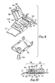
- Figures 9 and 10 illustrate another embodiment of the mechanical connector 14A.
- Mechanical connector 14A illustrated in Figures 9 and 10 is similar to mechanical connector 14 illustrated in Figures 1 through 5.
- the path of the securing of the strip of material 12 differs between the two embodiments.
- strip of material 12 is passed first under transverse bar 38 and back over transverse bar 38 whereupon it is impaled upon spikes 40 by hinged cover 42.
- Mechanical connector 14A, illustrated in Figures 9 and 10 has a plate 52 in place of transverse bar 38. Strip of material 12 passes over plate 52 where it is impaled upon spikes 40 and secured with hinged cover 42.
- the second end 24 of strip of material 12 then passes from connector 14A adjacent to hinged cover 42 for which a space is provided next to the first part 22 of mechanical connector 14A.
- All other aspects of mechanical connector 14A are identical to corresponding aspects of mechanical connector 14. Note that in the mechanical connector 14A the inner surface 16 of the strip of material 12 is forced by transverse ridges 50 into contact with the metallic electrically conductive second cover, back plate, 32 providing full 360 degree electrical continuity and skin contact around the interior of the adjustable conductive body strap.
- mechanical connector 14A has an element, or bar, 54 positioned adjacent hinged cover 42 above the path of the second end 24 of the strip of material 12 before the strip of material 12 passes over plate 52.
- Element 54 is positioned transverse to strip of material 12 and provides a convenient fulcrum around which the strip of material is pulled tight around the body part (not shown) and before the strip of material 12 is secured over spikes 40 in plate 52.
- Figures 1-10 have illustrated and described adjustable, electrically conductive body straps in general, and have described, in particular, a detailed example of two ways in which an adjustable conductive body strap may be constructed
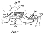
- Figure 11 illustrates the adjustable, conductive body strap 152 of the present invention.
- a mechanical connector 154 is formed from an outer piece 156 and an inner piece 158.
- the outer piece 156 and the inner piece 158 are secured together by means of a snap connector 160 and stud 162. Since outer piece 156 is on the exposed exterior surface of the adjustable, conductive body strap 152, outer piece 156 is constructed from an electrically insulative material such as a plastic material, and preferably from nylon or static dissipative plastic.
- inner piece 158 is on the interior surface of the adjustable conductive body strap 152, inner piece 158 is constructed from an electrically conductive material, such as stainless steel or another metal. Inner piece 158 contacts the skin of the wearer and provides an additional electrical contact point from the adjustable conductive body strap 152 to the wearer.
- the first end 20 of the strip of material 12 is received into one side of mechanical connector 154 from a first direction by a recess formed by the joining of outer piece 156 and inner piece 158. Having been so received the first end 20 of strip of material 12 is held in place, alternative, by stud 162, by one or more spikes similar to spikes 30 illustrated in Figure 4 (not shown), or both.
- the inner conductive surface 16 of the strip of material 12 contacts the electrically conductive inner piece 158.
- a slot 164 on the other side of inner piece 158 allows for second end 24 of the strip of material to pass, first over and then under inner piece 158 with inner piece 158 making electrical contact with the electrically conductive surface 16 of the strip of material 12.
- the second end 24 of strip of material 12 is then secured back to itself by an eight-ring 166. Since the eight-ring 166 is exposed to the exterior of the adjustable, conductive body strap 152, it is preferred that it be constructed of an electrically insulative material, again such as a plastic material, preferably nylon or static dissipative plastic.
- the second end 24 of the strip of material 12 is wrapped around the central member of eight-ring 166 and secured, by any suitable mechanism, such as stitching, to itself firmly securing the second end 24 of the strip of material 12 to the eight-ring 166.
- the strip of material 12 having been passed between the center leg and the two outer legs of eight-ring 166, then provides a readily readjustable mechanism whereby the user of the adjustable conductive body strap 152 may resize the adjustable conductive body strap 152 in a readily efficient manner. Since there are not free ends of the strip of material 12 exposed following the strip of material 12 being secured in mechanical connector 154, there is no danger of the electrically conductive surface 16 of the strip of material 12 being left exposed to the exterior of the adjustable conductive body strap 152.
- Snap 60 along with stud 62 form the electrical connection mechanism whereby an electrical ground cable may be connected to snap 160 and the adjustable conductive body strap 152 may be then connected to an electrical ground.
- inner piece 158 is electrically conductive and makes electrical contact to both the first end 20 and the electrically conductive surface 16 of the strip of material 12 near second end 24, dual parallel paths for the drainage of an accumulated electrostatic charge are provided.
- the adjustable, conductive body strap has full 360 degree electrical continuity and near full 360 degree electrical skin contact with the only exception being the portion between slot 164 and eight-ring 166 which is a reasonable tradeoff for the elimination of any exposure of the conductive surface 16 of strip material 12 and for the readily readjustable feature of eight-ring 166.
Landscapes
- Health & Medical Sciences (AREA)
- Engineering & Computer Science (AREA)
- Biomedical Technology (AREA)
- Nuclear Medicine, Radiotherapy & Molecular Imaging (AREA)
- Radiology & Medical Imaging (AREA)
- Life Sciences & Earth Sciences (AREA)
- Animal Behavior & Ethology (AREA)
- General Health & Medical Sciences (AREA)
- Public Health (AREA)
- Veterinary Medicine (AREA)
- Elimination Of Static Electricity (AREA)
- Adornments (AREA)
- Woven Fabrics (AREA)
- Knitting Of Fabric (AREA)
- Finger-Pressure Massage (AREA)
- Thermotherapy And Cooling Therapy Devices (AREA)
- Registering, Tensioning, Guiding Webs, And Rollers Therefor (AREA)
- Manufacturing Of Electric Cables (AREA)
- Package Frames And Binding Bands (AREA)
- Multi-Conductor Connections (AREA)
Priority Applications (1)
| Application Number | Priority Date | Filing Date | Title |
|---|---|---|---|
| AT88302990T ATE87163T1 (de) | 1987-04-13 | 1988-04-05 | Verstellbarer, leitender verbandsstreifen. |
Applications Claiming Priority (2)
| Application Number | Priority Date | Filing Date | Title |
|---|---|---|---|
| US07/037,616 US4720765A (en) | 1987-04-13 | 1987-04-13 | Adjustable, conductive body strap |
| US37616 | 1987-04-13 |
Publications (3)
| Publication Number | Publication Date |
|---|---|
| EP0287255A2 true EP0287255A2 (fr) | 1988-10-19 |
| EP0287255A3 EP0287255A3 (en) | 1989-03-29 |
| EP0287255B1 EP0287255B1 (fr) | 1993-03-17 |
Family
ID=21895308
Family Applications (1)
| Application Number | Title | Priority Date | Filing Date |
|---|---|---|---|
| EP88302990A Expired - Lifetime EP0287255B1 (fr) | 1987-04-13 | 1988-04-05 | Bande conductrice réglable |
Country Status (8)
| Country | Link |
|---|---|
| US (1) | US4720765A (fr) |
| EP (1) | EP0287255B1 (fr) |
| JP (1) | JP2599752B2 (fr) |
| AT (1) | ATE87163T1 (fr) |
| CA (1) | CA1316571C (fr) |
| DE (1) | DE3879249T2 (fr) |
| HK (1) | HK117094A (fr) |
| MY (1) | MY103070A (fr) |
Cited By (4)
| Publication number | Priority date | Publication date | Assignee | Title |
|---|---|---|---|---|
| AU598976B1 (en) * | 1988-10-31 | 1990-07-05 | American Telephone And Telegraph Company | Static electric discharge apparatus |
| AU605437B2 (en) * | 1988-10-31 | 1991-01-10 | American Telephone And Telegraph Company | Static electric discharge apparatus with active electrical circuit |
| EP0390345A3 (fr) * | 1989-03-27 | 1992-04-01 | Minnesota Mining And Manufacturing Company | Bracelet corporel conducteur ajustable |
| DE4217253C2 (de) * | 1992-05-25 | 2003-03-27 | Minnesota Mining & Mfg | Vorrichtung zum Verbinden einer leitfähigen Schicht mit einer Erdungsleitung zur Ableitung elektrostatischer Ladungen |
Families Citing this family (8)
| Publication number | Priority date | Publication date | Assignee | Title |
|---|---|---|---|---|
| US4845585A (en) * | 1987-04-13 | 1989-07-04 | Minnesota Mining And Manufacturing Company | Adjustable, conductive body strap |
| US4816964A (en) * | 1987-04-13 | 1989-03-28 | Minnesota Mining And Manufacturing Company | Adjustable, conductive body strap |
| US4873608A (en) * | 1988-02-05 | 1989-10-10 | Hakko Metal Industries Limited | Electric soldering iron |
| US5018044A (en) * | 1989-08-23 | 1991-05-21 | Minnesota Mining And Manufacturing Company | Dual conductor wristband |
| US4998178A (en) * | 1990-06-18 | 1991-03-05 | Minnesota Mining And Manufacturing Company | Adjustable, conductive body strap |
| US5184274A (en) * | 1990-09-07 | 1993-02-02 | Minnesota Mining And Manufacturing Company | Adjustable, elastic static control wristband |
| US5566427A (en) * | 1994-04-13 | 1996-10-22 | Lathrop; Kim N. | Strap clip and retainer |
| US7289310B1 (en) * | 2007-01-24 | 2007-10-30 | Chun-An Yuan | Adjustable static current discharging bracelet |
Family Cites Families (3)
| Publication number | Priority date | Publication date | Assignee | Title |
|---|---|---|---|---|
| JPS5521604Y2 (fr) * | 1975-07-01 | 1980-05-24 | ||
| US4398277A (en) * | 1981-07-27 | 1983-08-09 | Minnesota Mining And Manufacturing Company | Conductive elastomeric fabric and body strap |
| US4577256A (en) * | 1984-09-25 | 1986-03-18 | Semtronics Corporation | Woven stretchable grounding strap |
-
1987
- 1987-04-13 US US07/037,616 patent/US4720765A/en not_active Expired - Lifetime
-
1988
- 1988-03-22 MY MYPI88000295A patent/MY103070A/en unknown
- 1988-03-28 CA CA000562670A patent/CA1316571C/fr not_active Expired - Lifetime
- 1988-04-05 EP EP88302990A patent/EP0287255B1/fr not_active Expired - Lifetime
- 1988-04-05 AT AT88302990T patent/ATE87163T1/de not_active IP Right Cessation
- 1988-04-05 DE DE8888302990T patent/DE3879249T2/de not_active Expired - Lifetime
- 1988-04-12 JP JP63090150A patent/JP2599752B2/ja not_active Expired - Fee Related
-
1994
- 1994-10-27 HK HK117094A patent/HK117094A/en not_active IP Right Cessation
Cited By (4)
| Publication number | Priority date | Publication date | Assignee | Title |
|---|---|---|---|---|
| AU598976B1 (en) * | 1988-10-31 | 1990-07-05 | American Telephone And Telegraph Company | Static electric discharge apparatus |
| AU605437B2 (en) * | 1988-10-31 | 1991-01-10 | American Telephone And Telegraph Company | Static electric discharge apparatus with active electrical circuit |
| EP0390345A3 (fr) * | 1989-03-27 | 1992-04-01 | Minnesota Mining And Manufacturing Company | Bracelet corporel conducteur ajustable |
| DE4217253C2 (de) * | 1992-05-25 | 2003-03-27 | Minnesota Mining & Mfg | Vorrichtung zum Verbinden einer leitfähigen Schicht mit einer Erdungsleitung zur Ableitung elektrostatischer Ladungen |
Also Published As
| Publication number | Publication date |
|---|---|
| DE3879249T2 (de) | 1993-08-26 |
| EP0287255A3 (en) | 1989-03-29 |
| JPS63275303A (ja) | 1988-11-14 |
| MY103070A (en) | 1993-04-30 |
| EP0287255B1 (fr) | 1993-03-17 |
| HK117094A (en) | 1994-11-04 |
| CA1316571C (fr) | 1993-04-20 |
| US4720765A (en) | 1988-01-19 |
| JP2599752B2 (ja) | 1997-04-16 |
| DE3879249D1 (de) | 1993-04-22 |
| ATE87163T1 (de) | 1993-04-15 |
Similar Documents
| Publication | Publication Date | Title |
|---|---|---|
| US4816964A (en) | Adjustable, conductive body strap | |
| EP0287255B1 (fr) | Bande conductrice réglable | |
| US4845585A (en) | Adjustable, conductive body strap | |
| EP0420452A1 (fr) | Collier de serrage pour câble comportant une bande en forme d'échelle | |
| EP0462764B1 (fr) | Bracelet réglable et conducteur | |
| JP2557837Y2 (ja) | 伸縮自在に調整可能な静電気制御用腕輪 | |
| US5134538A (en) | Adjustable, conductive body strap | |
| US6707659B2 (en) | Heel grounder | |
| US5576924A (en) | Heel grounding device | |
| US6735070B2 (en) | Article for static charge dissipation | |
| CA1297938C (fr) | Agrafe pour bande de mise a la terre automatique | |
| US4755144A (en) | Static grounding buckle having continuous contact | |
| US2933651A (en) | Body grounding devices | |
| US6866128B2 (en) | Retractable anti-static devices and methods of using same | |
| US4885728A (en) | Electrical wrist band connector for a watch band | |
| US4194713A (en) | Tool holder and components thereof | |
| GB2224066A (en) | Buckle |
Legal Events
| Date | Code | Title | Description |
|---|---|---|---|
| PUAI | Public reference made under article 153(3) epc to a published international application that has entered the european phase |
Free format text: ORIGINAL CODE: 0009012 |
|
| AK | Designated contracting states |
Kind code of ref document: A2 Designated state(s): AT CH DE FR GB IT LI SE |
|
| PUAL | Search report despatched |
Free format text: ORIGINAL CODE: 0009013 |
|
| AK | Designated contracting states |
Kind code of ref document: A3 Designated state(s): AT CH DE FR GB IT LI SE |
|
| 17P | Request for examination filed |
Effective date: 19890831 |
|
| 17Q | First examination report despatched |
Effective date: 19910806 |
|
| ITF | It: translation for a ep patent filed | ||
| GRAA | (expected) grant |
Free format text: ORIGINAL CODE: 0009210 |
|
| AK | Designated contracting states |
Kind code of ref document: B1 Designated state(s): AT CH DE FR GB IT LI SE |
|
| REF | Corresponds to: |
Ref document number: 87163 Country of ref document: AT Date of ref document: 19930415 Kind code of ref document: T |
|
| REF | Corresponds to: |
Ref document number: 3879249 Country of ref document: DE Date of ref document: 19930422 |
|
| ITTA | It: last paid annual fee | ||
| ET | Fr: translation filed | ||
| PLBE | No opposition filed within time limit |
Free format text: ORIGINAL CODE: 0009261 |
|
| STAA | Information on the status of an ep patent application or granted ep patent |
Free format text: STATUS: NO OPPOSITION FILED WITHIN TIME LIMIT |
|
| 26N | No opposition filed | ||
| EAL | Se: european patent in force in sweden |
Ref document number: 88302990.2 |
|
| REG | Reference to a national code |
Ref country code: GB Ref legal event code: IF02 |
|
| PGFP | Annual fee paid to national office [announced via postgrant information from national office to epo] |
Ref country code: AT Payment date: 20070321 Year of fee payment: 20 |
|
| PGFP | Annual fee paid to national office [announced via postgrant information from national office to epo] |
Ref country code: SE Payment date: 20070427 Year of fee payment: 20 Ref country code: CH Payment date: 20070427 Year of fee payment: 20 |
|
| PGFP | Annual fee paid to national office [announced via postgrant information from national office to epo] |
Ref country code: DE Payment date: 20070531 Year of fee payment: 20 |
|
| REG | Reference to a national code |
Ref country code: CH Ref legal event code: PFA Owner name: MINNESOTA MINING AND MANUFACTURING COMPANY Free format text: MINNESOTA MINING AND MANUFACTURING COMPANY#3M CENTER, 2501 HUDSON ROAD P.O. BOX 33427#SAINT PAUL/MN (US) -TRANSFER TO- MINNESOTA MINING AND MANUFACTURING COMPANY#3M CENTER, 2501 HUDSON ROAD P.O. BOX 33427#SAINT PAUL/MN (US) |
|
| PGFP | Annual fee paid to national office [announced via postgrant information from national office to epo] |
Ref country code: GB Payment date: 20070425 Year of fee payment: 20 |
|
| PGFP | Annual fee paid to national office [announced via postgrant information from national office to epo] |
Ref country code: IT Payment date: 20070523 Year of fee payment: 20 |
|
| PGFP | Annual fee paid to national office [announced via postgrant information from national office to epo] |
Ref country code: FR Payment date: 20070417 Year of fee payment: 20 |
|
| REG | Reference to a national code |
Ref country code: GB Ref legal event code: PE20 Expiry date: 20080404 Ref country code: CH Ref legal event code: PL |
|
| EUG | Se: european patent has lapsed | ||
| PG25 | Lapsed in a contracting state [announced via postgrant information from national office to epo] |
Ref country code: GB Free format text: LAPSE BECAUSE OF EXPIRATION OF PROTECTION Effective date: 20080404 |