EP0287263A2 - Vorrichtung zum Verbinden eines Drahtes mit einer Motorklemme - Google Patents
Vorrichtung zum Verbinden eines Drahtes mit einer Motorklemme Download PDFInfo
- Publication number
- EP0287263A2 EP0287263A2 EP88303021A EP88303021A EP0287263A2 EP 0287263 A2 EP0287263 A2 EP 0287263A2 EP 88303021 A EP88303021 A EP 88303021A EP 88303021 A EP88303021 A EP 88303021A EP 0287263 A2 EP0287263 A2 EP 0287263A2
- Authority
- EP
- European Patent Office
- Prior art keywords
- wire
- motor
- terminal
- slot
- support
- Prior art date
- Legal status (The legal status is an assumption and is not a legal conclusion. Google has not performed a legal analysis and makes no representation as to the accuracy of the status listed.)
- Withdrawn
Links
Images


Classifications
-
- H—ELECTRICITY
- H01—ELECTRIC ELEMENTS
- H01F—MAGNETS; INDUCTANCES; TRANSFORMERS; SELECTION OF MATERIALS FOR THEIR MAGNETIC PROPERTIES
- H01F5/00—Coils
- H01F5/04—Arrangements of electric connections to coils, e.g. leads
-
- H—ELECTRICITY
- H01—ELECTRIC ELEMENTS
- H01R—ELECTRICALLY-CONDUCTIVE CONNECTIONS; STRUCTURAL ASSOCIATIONS OF A PLURALITY OF MUTUALLY-INSULATED ELECTRICAL CONNECTING ELEMENTS; COUPLING DEVICES; CURRENT COLLECTORS
- H01R4/00—Electrically-conductive connections between two or more conductive members in direct contact, i.e. touching one another; Means for effecting or maintaining such contact; Electrically-conductive connections having two or more spaced connecting locations for conductors and using contact members penetrating insulation
- H01R4/24—Connections using contact members penetrating or cutting insulation or cable strands
- H01R4/2416—Connections using contact members penetrating or cutting insulation or cable strands the contact members having insulation-cutting edges, e.g. of tuning fork type
- H01R4/2445—Connections using contact members penetrating or cutting insulation or cable strands the contact members having insulation-cutting edges, e.g. of tuning fork type the contact members having additional means acting on the insulation or the wire, e.g. additional insulation penetrating means, strain relief means or wire cutting knives
-
- H—ELECTRICITY
- H02—GENERATION; CONVERSION OR DISTRIBUTION OF ELECTRIC POWER
- H02K—DYNAMO-ELECTRIC MACHINES
- H02K5/00—Casings; Enclosures; Supports
- H02K5/04—Casings or enclosures characterised by the shape, form or construction thereof
- H02K5/22—Auxiliary parts of casings not covered by groups H02K5/06-H02K5/20, e.g. shaped to form connection boxes or terminal boxes
- H02K5/225—Terminal boxes or connection arrangements
Definitions
- This invention relates to an electric motor having a device for connecting a wire to a motor terminal.
- wires are connected to terminals of fractional horsepower electric motors, by soldering.
- the connection process is time consuming and moreover, a bared part of the wire adjacent to the soldered connection remains unsupported and is able to move about when subjected to vibration. This can lead to loosening of the joint.
- an electric motor comprising a terminal for electrical connection to a power supply, a wire support adjacent to the terminal, and a device for electrically connecting a wire to the terminal, the device being adapted to slidably connect with the terminal and having a slot for straddling and gripping a wire, supported by the wire support, as the device is connected to the terminal to make electrical contact with the wire.
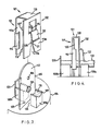
- Figure 1 shows a first embodiment of the invention.
- a device 1 is arranged to grip and to electrically connect a wire 2 with a terminal 3 which protrudes from an end cap 4 of an electric motor.
- terminal 3 will be in electrical connection with a brush inside the motor for supplying current to armature coils of the motor via a commutator.
- the invention is equally applicable to DC motors, AC motors and universal motors, but finds particular utility with fractional horsepower PMDC motors where component parts are small and space is often at a premium when installing such motors in appliances.
- Terminal 3 is a flat, metal, spade terminal having a first aperture 5 through which wire 2 may pass, and a second aperture 6 for cooperation with a dimple 7 on the device 1.
- the terminal 3 protrudes through a plastics end cap 4. Adjacent the terminal 3 and spaced therefrom is a wire support 8. Adjacent the terminal 3 and spaced therefrom is a wire support 8. Support 8 is integrally moulded with the end cap 4 and has a bifurcated end 9 forming a groove 10 which is arranged to support the wire 2.
- the groove 10 has a ribbed inner surface and a serrated edge 29.
- Wire 2 has a plastics coating 11 about a conducting stranded core 12 as is well known in the art.
- Device 1 is stamped and folded from sheet metal and comprises a planar portion 13 which has gripping portions 14 formed on opposite edges 15 by rolling over the material of the planar portion, as is well known in the connector art.
- slot 16 Formed in a lower end 27 of the planar portion 13 is a slot 16. Slot 16 has a widened V-shaped portion 17 which at its lower end 18 is wider than the outer diameter of wire 2.
- the V-shaped portion 17 tapers upwardly into a parallel sided slot portion 19 which is narrower than the diameter of the stranded core 12 of wire 2.
- the facing surfaces 20, 21 of the slot 16 are sharp, or they may carry a barb, so as to penetrate the plastics sleeve 11 on the wire 2 as the slot 16 is slid over the wire, as will be described more fully hereinafter.
- a clamping portion 22 is pressed out of the planar portion 13 and depends downwardly in a generally S-shape.
- a dimple 7 is pressed in the upper end 23 of the planar portion above an aperture 24 left by the pressed out clamping portion 22.
- the wire is laid on the support 8 with an end of the wire projecting across the gap 25 between the support 8 and terminal 3. It is preferable that the wire project into or through the aperture 5 so that it is supported on either side of the gap 25.
- the device 1 is then slid downwards over the terminal 3.
- the rolled gripping portions 14 are opened out slightly as they contact edges 26 of the terminal to enfold the edges and so grip the terminal as is well known in the connector art.
- the lower end 27 slides into the gap 25.
- the slot 16 is dimensioned so that the V-shaped portion 17 will ride over the wire 2, the wire being squeezed as the narrow end of the slot bears down on the wire, the wire being squeezed eventually into the parallel sided slot portion 19.
- the opposed surfaces 20, 21 may be sharp or barbed so as to penetrate the wire sleeve 11 so that the slot edges make physical and hence electrical contact with the wire core 12.
- the wire casing may be stripped from the wire in the region to be gripped by the device 1, before the wire is laid on the support 8.
- the clamping portion 22 bears down on the wire to press it into the groove 10, to prevent side ways movement of the wire in the region of the slot 16, which may otherwise cause the wire to free and perhaps break (see Figure 2).
- the serrated edge 29 of the groove 10 also serves to prevent longitudinal movement of the wire.
- the dimple 7 (on the rear of planar portion 13 as seen in Figure 1) cooperates with the aperture 6 to hold the device 1 on the terminal 3.
- two supports 108a, 108b are provided either side of the terminal 103, the wire 102 (see Figure 4) being laid through the aperture 105 and supported on each side by the supports 108a, 108b.
- a stop plate 130 is provided by support 108b to limit the insertion of the wire 2 through the aperture 105.
- the device 101 is in first and second parts 131, 132 which are integrally connected by a plate portion 133.
- First part 131 comprises planar portion 113a with a dimple 107; rolled gripping portions 114 and a slot 116.
- the second part 132 comprises a second planar portion 113b with a slot 116 and clamping portion 122.
- the device 101 may be formed by stamping and folding from metal sheet.
- the device 101 is slid over the terminal 103, the terminal lying between the planar portions 113a, 113b (see Figure 4).
- the slots 116 straddle and grip the wire 102, with clamping portion 122 bearing down on the wire 102 to press it into the groove 110 in support 108a.
- the wire 102 (not shown)may be pre-stripped, the facing surfaces 120, 121 of the grooves 116 being flat to grip the wire strands without cutting.
- FIG. 5 shows a third embodiment of the device 201.
- the device 201 comprises first and second parts 231, 232 comprising a first planar portion 213a having rolled gripping portion 214, and a second planar portion 213b having a slot 216 and clamping portion 222.
- the first and second parts are electrically separated and joined by a plastics cap 240, upper ends of the planar portions being embedded in the cap 240.
- a contact portion 241, 242 is provided, the contact portions being exposed on the top 243 of the cap 240.
- end cap 204 On the end cap 204 ( Figure 6) two spaced apart plastics supports 208a, 208b are provided to one side of the terminal 203. A stop 230 is formed on one support 208b adjacent the terminal 203. A stripped wire 202 is laid on the supports, its end 235 abutting the stop 230 so as to be electrically insulated from the terminal 203.
- the device 201 is slid onto the terminal 203, the first part 231 gripping the terminal 203 and the second part 232 straddling and gripping the wire 202, planar portion 213b sliding between the supports 208a, 208b and clamping portion 222 clamping the wire 202 into the groove 210b.
- a conducting bridge such as a metal finger, is placed across the exposed portions 241, 242.
- the finger may be part of a switch mechanism for the motor, and/or may be an electrical component such as a suppression element, choke, varistor etc.
- the exposed parts 241, 242 may be housed in a cavity in the plastics holder 240, for receiving a terminal, or terminals of a connector or electrical device.
- a support 308 for the wire 302 comprises three portions 308a, b, c, laid in a line parallel to the plane of the terminal 303, with a stop 330 on one portion 308c.
- Device 301 comprises a first planar portion 313a with rolled gripping portions 314 and a second integrally connected planar portion 313b.
- Two slot containing portions 351 project out of the plane of portion 313b and each has a slot 316 in its lower end 327.
- the first portion 313a is slid onto the terminal 303 as before and the slot containing portions 351 slide into the gaps 325 between the wire supports 308a, b, c, slots 316 straddling and gripping the wire 302, as before the slots may grip a bared wire 302 or be formed so as to penetrate a sleeve of the wire.
- This embodiment is also suitable for use with separate first and second parts or planar portions 313a, 313b as in Figure 5, integral connecting plate 333 being replaced by a plastics holder (243) to allow the incorporation of a switch mechanism or electrical component.
- a pair of devices 1, 101, 201, 301 may be mounted in an insulating cap which is arranged to fit over an end of the motor for simultaneous connection of wires to respective terminals.
- the device is particularly suitable for use with pre-tinned stranded wire which is treated to melt the solder into a coherent cylindrical mass suitable for gripping by the slot edges.
Landscapes
- Engineering & Computer Science (AREA)
- Power Engineering (AREA)
- Motor Or Generator Frames (AREA)
- Connections Arranged To Contact A Plurality Of Conductors (AREA)
- Insulation, Fastening Of Motor, Generator Windings (AREA)
- Motor Or Generator Current Collectors (AREA)
Applications Claiming Priority (2)
| Application Number | Priority Date | Filing Date | Title |
|---|---|---|---|
| GB08708786A GB2203600A (en) | 1987-04-13 | 1987-04-13 | A device for connecting a wire to a terminal |
| GB8708786 | 1987-04-13 |
Publications (2)
| Publication Number | Publication Date |
|---|---|
| EP0287263A2 true EP0287263A2 (de) | 1988-10-19 |
| EP0287263A3 EP0287263A3 (de) | 1990-05-02 |
Family
ID=10615721
Family Applications (1)
| Application Number | Title | Priority Date | Filing Date |
|---|---|---|---|
| EP88303021A Withdrawn EP0287263A3 (de) | 1987-04-13 | 1988-04-05 | Vorrichtung zum Verbinden eines Drahtes mit einer Motorklemme |
Country Status (5)
| Country | Link |
|---|---|
| US (1) | US4904203A (de) |
| EP (1) | EP0287263A3 (de) |
| JP (1) | JPS63179759U (de) |
| CN (1) | CN88204123U (de) |
| GB (1) | GB2203600A (de) |
Cited By (3)
| Publication number | Priority date | Publication date | Assignee | Title |
|---|---|---|---|---|
| GB2210209B (en) * | 1987-09-17 | 1991-07-24 | Bicc Plc | Terminating insulated conductors |
| EP0563409A1 (de) * | 1992-03-27 | 1993-10-06 | Siemens Aktiengesellschaft | Elektrische Steckkontakt-Verbindung |
| WO2011019466A1 (en) * | 2009-08-11 | 2011-02-17 | Illinois Tool Works Inc. | Insulation displacement terminal system with regulated wire compression |
Families Citing this family (13)
| Publication number | Priority date | Publication date | Assignee | Title |
|---|---|---|---|---|
| US5643007A (en) * | 1996-09-13 | 1997-07-01 | Abb Power T&D Company Inc. | Transformer tap connector |
| JP3276876B2 (ja) * | 1997-03-19 | 2002-04-22 | 矢崎総業株式会社 | 圧接端子及び圧接端子の製造方法 |
| CN100345469C (zh) * | 2002-11-08 | 2007-10-24 | 南京Lg同创彩色显示系统有限责任公司 | 电缆支架接地装置 |
| US7354296B1 (en) | 2006-09-21 | 2008-04-08 | Hubbell Incorporated | Contact termination member for an electrical receptacle |
| US7494362B2 (en) * | 2007-04-26 | 2009-02-24 | J.S.T. Corporation | High current sealed connector plug assembly |
| US7637761B1 (en) * | 2008-08-11 | 2009-12-29 | Gm Global Technology Operations, Inc. | Method and apparatus to connect a wiring harness to an electric machine |
| US8974245B2 (en) | 2013-08-05 | 2015-03-10 | Hubbell Incorporated | Grounding electrical connector |
| JP6334581B2 (ja) * | 2016-01-27 | 2018-05-30 | 株式会社東海理化電機製作所 | インシュレータ |
| CN105552599B (zh) * | 2016-02-02 | 2017-11-07 | 江苏万丰电气有限公司 | 电线快速连接器 |
| JP6660210B2 (ja) * | 2016-02-29 | 2020-03-11 | マブチモーター株式会社 | モータ |
| CN107039792A (zh) * | 2016-12-14 | 2017-08-11 | 上海艾铭思汽车控制系统有限公司 | 一种电机插片及电机系统 |
| TWI754527B (zh) * | 2021-01-27 | 2022-02-01 | 宏正自動科技股份有限公司 | 固定端子 |
| RU206044U1 (ru) * | 2021-06-07 | 2021-08-17 | Общество с ограниченной ответственностью "ЭнергоТэк" | Наконечник для трубчатого кабелепровода |
Family Cites Families (22)
| Publication number | Priority date | Publication date | Assignee | Title |
|---|---|---|---|---|
| US2694189A (en) * | 1953-08-21 | 1954-11-09 | Bell Telephone Labor Inc | Solderless wire terminal |
| US3016510A (en) * | 1958-07-23 | 1962-01-09 | Blonder Tongue Elect | Electrical clamp-and-connector |
| US3083349A (en) * | 1961-09-18 | 1963-03-26 | Blonder Tongue Elect | Transmission-line clamp-and-connector |
| US3350679A (en) * | 1964-04-23 | 1967-10-31 | Amp Inc | Electrical connections |
| US3257635A (en) * | 1964-01-20 | 1966-06-21 | Amp Inc | Electrical connections |
| US3391379A (en) * | 1966-07-20 | 1968-07-02 | Gen Electric | Electrical connector for establishing a multipoint contact with an insulated conductor |
| US3760339A (en) * | 1971-05-05 | 1973-09-18 | Black & Decker Mfg Co | Connector for plug in field |
| US4013332A (en) * | 1975-06-30 | 1977-03-22 | Lloyd A. Heneveld, trustee | Electrical connector |
| GB1500303A (en) * | 1975-10-08 | 1978-02-08 | Carr Fastener Co Ltd | Electrical connection assemblies |
| AR208483A1 (es) * | 1975-11-10 | 1976-12-27 | Amp Inc | Terminal electrico |
| DE2553558C3 (de) * | 1975-11-28 | 1980-02-28 | Karl 7519 Oberderdingen Fischer | Elektrischer Steckanschluß |
| DE2610461C3 (de) * | 1976-03-11 | 1980-08-21 | Krone Gmbh, 1000 Berlin | Vorrichtung und Verfahren zur Herstellung eines löt-, schraub- und abisolierfreien Kontaktes an einem feststehenden Anschlunelement, insbesondere für die Fernmeldelinientechnik |
| US4039239A (en) * | 1976-03-24 | 1977-08-02 | Amp Incorporated | Wire slot clip |
| CA1082325A (en) * | 1977-05-06 | 1980-07-22 | Charles H. Weidler | Electrical connectors with terminals having wire- receiving portions for inserting wires |
| FR2408923A1 (fr) * | 1977-09-21 | 1979-06-08 | Alsthom Cgee | Borne a raccordement rapide |
| US4124265A (en) * | 1977-11-10 | 1978-11-07 | Minnesota Mining And Manufacturing Company | Quick slide connector |
| US4181393A (en) * | 1978-03-17 | 1980-01-01 | Amp Incorporated | Interconnecting means for coil windings and overload protector |
| GB2022939B (en) * | 1978-05-26 | 1982-10-20 | Lucas Industries Ltd | Electrical terminal assembly |
| US4220390A (en) * | 1978-07-25 | 1980-09-02 | Amp Incorporated | Terminating means for terminating more than one wire in a single slotted terminal |
| US4322647A (en) * | 1979-11-23 | 1982-03-30 | The Scott & Fetzer Company | Motor assembly |
| FR2507393A1 (fr) * | 1981-06-05 | 1982-12-10 | Ctm | Borne de contact electrique pour branchement rapide d'un conducteur isole |
| US4740171A (en) * | 1987-02-24 | 1988-04-26 | Dayco Products, Inc. | Vacuum cleaner hose and terminal connector therefor |
-
1987
- 1987-04-13 GB GB08708786A patent/GB2203600A/en not_active Withdrawn
-
1988
- 1988-04-05 EP EP88303021A patent/EP0287263A3/de not_active Withdrawn
- 1988-04-07 JP JP1988047280U patent/JPS63179759U/ja active Pending
- 1988-04-08 US US07/179,233 patent/US4904203A/en not_active Expired - Fee Related
- 1988-04-13 CN CN88204123U patent/CN88204123U/zh not_active Withdrawn
Cited By (5)
| Publication number | Priority date | Publication date | Assignee | Title |
|---|---|---|---|---|
| GB2210209B (en) * | 1987-09-17 | 1991-07-24 | Bicc Plc | Terminating insulated conductors |
| EP0563409A1 (de) * | 1992-03-27 | 1993-10-06 | Siemens Aktiengesellschaft | Elektrische Steckkontakt-Verbindung |
| TR26811A (tr) * | 1992-03-27 | 1994-08-08 | Siemens Ag | Elektrik priz baglantisi. |
| WO2011019466A1 (en) * | 2009-08-11 | 2011-02-17 | Illinois Tool Works Inc. | Insulation displacement terminal system with regulated wire compression |
| US8900005B2 (en) | 2009-08-11 | 2014-12-02 | Pancon Llc | Insulation displacement terminal system with regulated wire compression |
Also Published As
| Publication number | Publication date |
|---|---|
| EP0287263A3 (de) | 1990-05-02 |
| GB8708786D0 (en) | 1987-05-20 |
| CN88204123U (zh) | 1988-11-30 |
| US4904203A (en) | 1990-02-27 |
| JPS63179759U (de) | 1988-11-21 |
| GB2203600A (en) | 1988-10-19 |
Similar Documents
| Publication | Publication Date | Title |
|---|---|---|
| US4904203A (en) | Device for connecting a wire to a motor terminal | |
| US4171857A (en) | Cleat connector for insulated wires | |
| US4130331A (en) | Solderless connector for terminating a magnet wire or the like | |
| US3967148A (en) | Brush holder assembly | |
| CA1286741C (en) | Cutting/clamping sleeve contact | |
| US12573794B2 (en) | Electrical wiring devices with screwless wire terminals | |
| US4895526A (en) | Connecting terminal block for electrical apparatus | |
| CN113422227A (zh) | 电插座、电源线连接器、电源线插头和电气布线装置 | |
| EP0029836B1 (de) | Elektrische verbinder | |
| PL323814A1 (en) | Connecting terminal for electric leads | |
| HK18887A (en) | An armature | |
| JP4638884B2 (ja) | 統合ブラシホルダ保持システム | |
| US20230299511A1 (en) | Electrical wiring devices with screwless wire terminals | |
| CA2219668A1 (en) | Connecting clamp for electrical conductors | |
| KR100318843B1 (ko) | 소음억제정류자와소음억제요소를정류자단편에접속하는방법 | |
| JP2644239B2 (ja) | 電機子 | |
| US4659164A (en) | Diode connector | |
| JPH104654A (ja) | 結合型の整流子ブラシ保持クリップ兼電気コネクタ | |
| US4218109A (en) | Electrical connector assembly | |
| EP0029328A1 (de) | Konstruktion eines elektrischen Motors | |
| GB8518141D0 (en) | Electrical crimp connection | |
| WO2023177809A1 (en) | Electrical wiring devices with screwless wire terminals | |
| US4611874A (en) | Device for making LSA-PLUS contact with conductor wires of different types and sizes | |
| EP0145315A3 (de) | Verbindungsvorrichtung für in kurzen Abständen angeordnete Leiter und dafür bestimmter elektrischer Kontaktanschluss | |
| JPH0410715B2 (de) |
Legal Events
| Date | Code | Title | Description |
|---|---|---|---|
| PUAI | Public reference made under article 153(3) epc to a published international application that has entered the european phase |
Free format text: ORIGINAL CODE: 0009012 |
|
| AK | Designated contracting states |
Kind code of ref document: A2 Designated state(s): DE FR GB IT |
|
| PUAL | Search report despatched |
Free format text: ORIGINAL CODE: 0009013 |
|
| AK | Designated contracting states |
Kind code of ref document: A3 Designated state(s): DE FR GB IT |
|
| RAP1 | Party data changed (applicant data changed or rights of an application transferred) |
Owner name: JOHNSON ELECTRIC S.A. |
|
| STAA | Information on the status of an ep patent application or granted ep patent |
Free format text: STATUS: THE APPLICATION IS DEEMED TO BE WITHDRAWN |
|
| 18D | Application deemed to be withdrawn |
Effective date: 19901106 |