EP0287350B1 - Système sous vide pour recueillir des eaux usées - Google Patents
Système sous vide pour recueillir des eaux usées Download PDFInfo
- Publication number
- EP0287350B1 EP0287350B1 EP88303325A EP88303325A EP0287350B1 EP 0287350 B1 EP0287350 B1 EP 0287350B1 EP 88303325 A EP88303325 A EP 88303325A EP 88303325 A EP88303325 A EP 88303325A EP 0287350 B1 EP0287350 B1 EP 0287350B1
- Authority
- EP
- European Patent Office
- Prior art keywords
- vacuum
- chamber
- pump
- tank
- pipe
- Prior art date
- Legal status (The legal status is an assumption and is not a legal conclusion. Google has not performed a legal analysis and makes no representation as to the accuracy of the status listed.)
- Expired
Links
- 239000010865 sewage Substances 0.000 title claims description 36
- XLYOFNOQVPJJNP-UHFFFAOYSA-N water Substances O XLYOFNOQVPJJNP-UHFFFAOYSA-N 0.000 claims description 15
- 239000007787 solid Substances 0.000 claims description 7
- 239000002245 particle Substances 0.000 claims description 5
- 239000007788 liquid Substances 0.000 claims description 4
- 239000010797 grey water Substances 0.000 claims description 2
- 230000008878 coupling Effects 0.000 description 3
- 238000010168 coupling process Methods 0.000 description 3
- 238000005859 coupling reaction Methods 0.000 description 3
- 238000011010 flushing procedure Methods 0.000 description 3
- 239000013505 freshwater Substances 0.000 description 3
- 238000012423 maintenance Methods 0.000 description 3
- 238000000746 purification Methods 0.000 description 2
- 239000011343 solid material Substances 0.000 description 2
- 230000001419 dependent effect Effects 0.000 description 1
- 238000011161 development Methods 0.000 description 1
- 230000018109 developmental process Effects 0.000 description 1
- 239000003651 drinking water Substances 0.000 description 1
- 235000020188 drinking water Nutrition 0.000 description 1
- 230000000694 effects Effects 0.000 description 1
- 239000012530 fluid Substances 0.000 description 1
- 239000000463 material Substances 0.000 description 1
- -1 or more correctly Substances 0.000 description 1
- 229920003023 plastic Polymers 0.000 description 1
- 239000004033 plastic Substances 0.000 description 1
- 239000007858 starting material Substances 0.000 description 1
- 210000002700 urine Anatomy 0.000 description 1
- 239000002351 wastewater Substances 0.000 description 1
Images
Classifications
-
- E—FIXED CONSTRUCTIONS
- E03—WATER SUPPLY; SEWERAGE
- E03F—SEWERS; CESSPOOLS
- E03F1/00—Methods, systems, or installations for draining-off sewage or storm water
- E03F1/006—Pneumatic sewage disposal systems; accessories specially adapted therefore
Definitions
- the present invention relates to collecting arrangement for vacuum sewage collecting systems and comprises a vacuum tank which through a supply pipe is connected to toilets, drainage tanks for urinals, greywater tanks etc., and a vacuum pump which through a suction pipe provides the necessary vacuum in the vacuum tank.
- Vacuum sewage collecting systems for toilets have already been known for several decades. Such systems were primarily developed for use onboard airplanes and railway trains. Espesially with regard to the airplanes, it was necessary to reduce the amount of water being carried with the planes to reduce the total weight.
- an important advantage with the vacuum drainage systems for toilets is that the amount of water being used for each flushing operation is very small. While the conventional toilets use 8-10 litres of water for each flushing operation, the vacuum toilets needs less than 1,5 liter.
- vacuum sewage collecting systems are also encumbered with practical as well as operational problems.
- the vacuum in the vacuum tank is provided by means of a vacuum pump, while the sewage in the vacuum tank is pumped out of the tank by means of a separate centrifugal pump.
- the vacuum pump has to be stopped, resulting in operations stoppage (the toilets can not be used).
- the users are using the toilets for other purposes than what they were initially intended for, i.e. the users are throwing garbage in the form of plastics bags, bottle caps, hand towels, sanitary ware or the like into the toilets.
- Such articles tend to pack the impeller of the centrifugal pump and prevent emptying of the vacuum tank, which again results in operations stoppage and an increase in maintenance costs.
- the vacuum sewage collecting system consists of a vacuum tank 1, which on one side is connected to a supply line 6 and on the other side is connected to a suction pipe 7 coupled to vacuum pumps 4.
- the vacuum tank 1 is divided into two chambers by means of a "dividing plate" 10.
- the dividing plate consists of a grating, a perforated plate or the like, and is partly conical with a partly bent pipe piece 16 which protrudes dowmwardly from the centre of the plate 10 and partly in to the lower, first 8 of the two chambers 8 and 9. Sewage in the form of water mixed with stools, urine, sanitary ware etc. flows into the first chamber 8 from toilets, urinals etc. (not shown) through the supply pipe 6. Water, or more correctly, fluid components flowing into the first chamber 8 can freely flow into the upper, second chamber 9 through the grating 10.
- the solid components arriving in the first chamber 8 are, however, ground by means of a macerator or grinder 3 which is provided in connection with the lower part of the chamber 8 and is pumped together with the liquid present to the second chamber 9 via a connecting pipe 11.
- the macerator may be a combined grinder/pump device, or a separately driven grinder which is connected to a separately driven pump. Further, the macerator may be continiously or intermittently driven. The kind of operation to be choosen in this connection depends upon the capasity of the macerator, the amount of material to be macerated and so on.
- Sewage, air and ground, solid materials which is present in the second chamber 9, is pumped via the suction pipe 7 out of the chamber by means of a vacuum pump in the form of a screw pump 4.
- the sewage and the solid particles are further transported through the drain pipe 13 to a not shown storage tank, purifying plant or the like, while the air is ventilated through an air escape pipe 16.
- the vacuum collecting unit is provided with two separately driven screw pumps 4, which by means of pipes 14, 15 and two-way valves 5, can be driven separately, or be coupled in parallel and driven simultaneously. This is done for safety reasons to avoid operational stoppage, and to maintain a reserve capasity for the unit.
- the vacuum in the vacuum tank 1, is maintained on an adequate level, i.e. 30-40%, by means of the screw pumps 4 which is started and stopped by means of an operating unit, not shown.
- the pump operation unit may be in the form of a vacuum sensor (pressure switch) disposed in the tank 1 and which is coupled to a starter relay for the pumps.
- supply pipes 12 are coupled to the suction inlet of the pumps to supply feed water to these.
- the feed water is supplied via the pipes 12 from a feed water tank 2 which is disposed on the drain pipes 13.
- the feed water is sewage from the pumps 4. It is, however, also possible to use waste water or fresh water instead of sewage.
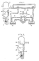
- Fig. 2 reveals an other vacuum tank 1 according to the invention. Also in this example the vacuum tank is divided into two chambers 8, 9.
- the dividing plate consists, however, of a plate 17 which is provided with an upwardly protruding pipe 18.
- the pipe 18 reaches some distance up into the upper chamber 9, and connects this chamber with the lower chamber 8. Air entering the lower chamber 8 will flow through the pipe 18 and into the upper chamber 9, while the sewage together with solid particles entering the lower chamber 9 will be macerated by the macerator and thereafter transported to the upper chamber 9 via the connecting pipe 19.
- the macerator is started by a signal from a level switch 20 which is disposed in the lower chamber 8 and is stopped by means of a timing relay.
- the object of the pipe 18 is, as indicated above, primarily to let the air flow freely into the upper chamber 9 to obtain equal pressure in the two chambers 8, 9. However, the pipe 18 will also serve as a return pipe if the sewage in the upper chamber reaches the level where the pipe 18 ends.
- the advantage with the vacuum tank shown in Fig. 2 is that the macerator will be in operation only when necessary, i.e. when the sewage reaches above the level where the level switch 20 is activated. In the example shown in Fig. 1, the macerator has to be in operation longer periods of time to be sure that all of the solid components in the chamber is macerated.
- the supply lines 6 and the macerator 3 is coupled to the lower chamber 8, whilst suction pipe 7 is coupled to the upper chamber 9. It is, however, within the frame of the invention possible to arrange these couplings opposite, i.e. by coupling the supply line 6 and the macerator 3 to the upper chamber 9 and by coupling the suction pipe 7 to the lower chamber 8. In such instance it is natural to use a macerator 3 in the form of a grinder without a pump and arrange this in close connection to the dividing plate 10, 17 so that the solid particles being present in the chamber 9, and which are ground by grinder, falls freely into the lower chamber 8.
- a vertical dividing wall or plate thereby having two side by side disposed chambers, instead of a horisontal dividing plate 10, 17 as shown in Fig. 1 and 2.
Landscapes
- Health & Medical Sciences (AREA)
- Life Sciences & Earth Sciences (AREA)
- Engineering & Computer Science (AREA)
- Hydrology & Water Resources (AREA)
- Public Health (AREA)
- Water Supply & Treatment (AREA)
- Sewage (AREA)
- Cleaning In General (AREA)
- Sink And Installation For Waste Water (AREA)
- Electrical Discharge Machining, Electrochemical Machining, And Combined Machining (AREA)
- Cyclones (AREA)
Claims (5)
par l'intermédiaire d'une plaque ou paroi séparatrice (10) le réservoir à vide (1) est divisé en deux chambres, dont la première chambre (8) à laquelle est raccordé le conduit d'amenée et une deuxième chambre (9) à laquelle est raccordé le conduit de vide (7), un broyeur ou décanteur (3) étant raccordé à la première chambre (8) pour broyer les matières solides et les transporter avec le liquide (boues et eaux sales) de la première chambre (8) vers la deuxième chambre (9) au moyen d'un conduit de raccord (11), le vide dans le réservoir à vide (1) étant assuré par une pompe à vide (4) adaptée pour pomper le liquide ainsi que les matières solides broyées depuis le réservoir (1) vers un réservoir d'entreposage ou autre.
la pompe à vide (4) est sous forme de pompe à vis, ou de deux ou plusieurs pompes à commande séparée et par des conduits (14, 15) des pompes à vis reliées en parallèle admettant le fonctionnement simple ou simultané, la/les pompe(s) (4) comportant des conduits d'amenée d'eau (12) apportant l'eau d'amenée aux entrées de pompes.
les conduits d'amenée d'eau (12) sont raccordés à un réservoir d'amenée d'eau (2) disposé sur le conduit de décharge (13) de la pompe à vis, l'eau d'amenée étant les eaux sales provenant du réservoir à vide (1).
la plaque séparatrice (10) est sous forme de plaque perforée, grille ou autre.
la plaque séparatrice (17) est munie d'un conduit (18) remontant dans la deuxième chambre (9), raccordant la chambre inférieure (8) à la chambre supérieure (9), et le décanteur est démarré par un rupteur de niveau (20) dans la chambre (8) et arrêté par un rupteur à minuterie ou un relais.
Applications Claiming Priority (2)
| Application Number | Priority Date | Filing Date | Title |
|---|---|---|---|
| NO871539A NO165502C (no) | 1987-04-13 | 1987-04-13 | Oppsamlingsanordning for vakuumavloepssystem. |
| NO871539 | 1987-04-13 |
Publications (3)
| Publication Number | Publication Date |
|---|---|
| EP0287350A2 EP0287350A2 (fr) | 1988-10-19 |
| EP0287350A3 EP0287350A3 (en) | 1989-01-18 |
| EP0287350B1 true EP0287350B1 (fr) | 1991-08-21 |
Family
ID=19889857
Family Applications (1)
| Application Number | Title | Priority Date | Filing Date |
|---|---|---|---|
| EP88303325A Expired EP0287350B1 (fr) | 1987-04-13 | 1988-04-13 | Système sous vide pour recueillir des eaux usées |
Country Status (5)
| Country | Link |
|---|---|
| EP (1) | EP0287350B1 (fr) |
| DE (1) | DE3864300D1 (fr) |
| ES (1) | ES2026253T3 (fr) |
| FI (1) | FI87823C (fr) |
| NO (1) | NO165502C (fr) |
Cited By (1)
| Publication number | Priority date | Publication date | Assignee | Title |
|---|---|---|---|---|
| DE102011000732B3 (de) * | 2011-02-15 | 2012-08-09 | Roediger Vacuum Gmbh | Drehkolbenpumpe |
Families Citing this family (7)
| Publication number | Priority date | Publication date | Assignee | Title |
|---|---|---|---|---|
| NO167931B (no) * | 1989-03-03 | 1991-09-16 | Jets Systemer As | Vacuum avloepssystem |
| NO314734B3 (no) * | 2001-05-29 | 2003-05-12 | Jets As | Væskeringspumpe av skruetypen |
| FI125301B (fi) | 2006-12-21 | 2015-08-31 | Evac Oy | Alipaineviemärijärjestelmä ja menetelmä alipaineviemärin käyttämiseksi |
| DK2997262T3 (da) | 2013-05-16 | 2022-03-07 | Jets As | Funktionel udformning af en væskeringsskruepumpe |
| CN110431367B (zh) | 2017-03-23 | 2021-08-27 | 喷射器股份有限公司 | 积聚和排泄来自制冷和冷却装置的除霜水和冷凝水的装置 |
| CN109794195A (zh) * | 2019-03-21 | 2019-05-24 | 中国铁路设计集团有限公司 | 一种防堵型真空罐装置 |
| AT525155B1 (de) | 2021-06-14 | 2023-02-15 | Eoos Next Gmbh | Vakuumtoilette sowie ein Vakuumtank für eine Vakuumtoilette |
Family Cites Families (4)
| Publication number | Priority date | Publication date | Assignee | Title |
|---|---|---|---|---|
| FR2050775A5 (fr) * | 1969-06-24 | 1971-04-02 | Baudot Hardoll | |
| FR2366186A1 (fr) * | 1976-10-04 | 1978-04-28 | Seureca | Installation pour collecter et evacuer un melange d'eau et de dechets |
| US4179371A (en) * | 1978-03-20 | 1979-12-18 | Burton Mechanical Contractors, Inc. | Vacuum sewage system |
| DE3042619C2 (de) * | 1980-11-12 | 1983-02-03 | Woma-Apparatebau Wolfgang Maasberg & Co Gmbh, 4100 Duisburg | Vorrichtung zur Kanal- und Grubenreinigung |
-
1987
- 1987-04-13 NO NO871539A patent/NO165502C/no not_active IP Right Cessation
-
1988
- 1988-04-13 EP EP88303325A patent/EP0287350B1/fr not_active Expired
- 1988-04-13 DE DE8888303325T patent/DE3864300D1/de not_active Expired - Lifetime
- 1988-04-13 ES ES198888303325T patent/ES2026253T3/es not_active Expired - Lifetime
- 1988-04-13 FI FI881705A patent/FI87823C/fi not_active IP Right Cessation
Cited By (1)
| Publication number | Priority date | Publication date | Assignee | Title |
|---|---|---|---|---|
| DE102011000732B3 (de) * | 2011-02-15 | 2012-08-09 | Roediger Vacuum Gmbh | Drehkolbenpumpe |
Also Published As
| Publication number | Publication date |
|---|---|
| EP0287350A2 (fr) | 1988-10-19 |
| FI881705A0 (fi) | 1988-04-13 |
| FI881705A7 (fi) | 1988-10-14 |
| EP0287350A3 (en) | 1989-01-18 |
| DE3864300D1 (de) | 1991-09-26 |
| FI87823B (fi) | 1992-11-13 |
| ES2026253T3 (es) | 1992-04-16 |
| FI87823C (fi) | 1993-02-25 |
| NO165502C (no) | 1991-02-20 |
| NO871539L (no) | 1988-10-14 |
| NO165502B (no) | 1990-11-12 |
| NO871539D0 (no) | 1987-04-13 |
Similar Documents
| Publication | Publication Date | Title |
|---|---|---|
| US4034421A (en) | Vacuum sewer system including a collecting tank | |
| US4199828A (en) | Vacuum toilet apparatus for mobile units | |
| JP2808186B2 (ja) | 真空排水システム | |
| US4144167A (en) | Sewage treatment system | |
| KR100408869B1 (ko) | 진공오물처리시스템및진공오물처리방법 | |
| CA2372390A1 (fr) | Dispositif de traitement des eaux usees | |
| US8381324B2 (en) | Vacuum sewage system | |
| US4297751A (en) | Sewer system | |
| CN2659957Y (zh) | 水面清洁设备 | |
| EP0287350B1 (fr) | Système sous vide pour recueillir des eaux usées | |
| US10557256B2 (en) | Holding tank for portable toilet | |
| SE9704146D0 (sv) | Mobil avvattningsenhet samt förfarande för avvattning av vatteninnehållande slam | |
| CN208320129U (zh) | 一种污水处理装置 | |
| CN211945144U (zh) | 一种用于输煤栈桥的环保型循环冲洗装置 | |
| CN110015312A (zh) | 列车及列车供水系统 | |
| CA1046008A (fr) | Systeme de manutention de dechets | |
| US4488963A (en) | Sewage system for waste water | |
| EP1179643A2 (fr) | Système d'assainissement sous vide | |
| EP1291468A2 (fr) | Systeme d'evacuation a vide equipe d'une citerne d'eaux residuelles de retenue temporelle | |
| JP2684526B2 (ja) | 真空式汚水集排水装置と真空式下水道 | |
| SU1101414A1 (ru) | Установка дл обработки сточных вод | |
| SU1234369A1 (ru) | Установка дл очистки сточных вод от нефтепродуктов | |
| CN206529380U (zh) | 高效的生物降解含油废水的容器 | |
| JPS6111337Y2 (fr) | ||
| CN209721901U (zh) | 一种吸污净化车 |
Legal Events
| Date | Code | Title | Description |
|---|---|---|---|
| PUAI | Public reference made under article 153(3) epc to a published international application that has entered the european phase |
Free format text: ORIGINAL CODE: 0009012 |
|
| AK | Designated contracting states |
Kind code of ref document: A2 Designated state(s): DE ES FR GB NL |
|
| PUAL | Search report despatched |
Free format text: ORIGINAL CODE: 0009013 |
|
| AK | Designated contracting states |
Kind code of ref document: A3 Designated state(s): DE ES FR GB NL |
|
| 17P | Request for examination filed |
Effective date: 19890714 |
|
| 17Q | First examination report despatched |
Effective date: 19901008 |
|
| GRAA | (expected) grant |
Free format text: ORIGINAL CODE: 0009210 |
|
| AK | Designated contracting states |
Kind code of ref document: B1 Designated state(s): DE ES FR GB NL |
|
| REF | Corresponds to: |
Ref document number: 3864300 Country of ref document: DE Date of ref document: 19910926 |
|
| ET | Fr: translation filed | ||
| REG | Reference to a national code |
Ref country code: ES Ref legal event code: FG2A Ref document number: 2026253 Country of ref document: ES Kind code of ref document: T3 |
|
| PLBE | No opposition filed within time limit |
Free format text: ORIGINAL CODE: 0009261 |
|
| STAA | Information on the status of an ep patent application or granted ep patent |
Free format text: STATUS: NO OPPOSITION FILED WITHIN TIME LIMIT |
|
| 26N | No opposition filed | ||
| REG | Reference to a national code |
Ref country code: GB Ref legal event code: IF02 |
|
| PGFP | Annual fee paid to national office [announced via postgrant information from national office to epo] |
Ref country code: NL Payment date: 20040406 Year of fee payment: 17 |
|
| PGFP | Annual fee paid to national office [announced via postgrant information from national office to epo] |
Ref country code: ES Payment date: 20040420 Year of fee payment: 17 |
|
| PG25 | Lapsed in a contracting state [announced via postgrant information from national office to epo] |
Ref country code: ES Free format text: LAPSE BECAUSE OF NON-PAYMENT OF DUE FEES Effective date: 20050414 |
|
| PG25 | Lapsed in a contracting state [announced via postgrant information from national office to epo] |
Ref country code: NL Free format text: LAPSE BECAUSE OF NON-PAYMENT OF DUE FEES Effective date: 20051101 |
|
| NLV4 | Nl: lapsed or anulled due to non-payment of the annual fee |
Effective date: 20051101 |
|
| REG | Reference to a national code |
Ref country code: ES Ref legal event code: FD2A Effective date: 20050414 |
|
| PGFP | Annual fee paid to national office [announced via postgrant information from national office to epo] |
Ref country code: DE Payment date: 20070405 Year of fee payment: 20 |
|
| PGFP | Annual fee paid to national office [announced via postgrant information from national office to epo] |
Ref country code: GB Payment date: 20070411 Year of fee payment: 20 |
|
| PGFP | Annual fee paid to national office [announced via postgrant information from national office to epo] |
Ref country code: FR Payment date: 20070411 Year of fee payment: 20 |
|
| REG | Reference to a national code |
Ref country code: GB Ref legal event code: PE20 Expiry date: 20080412 |
|
| PG25 | Lapsed in a contracting state [announced via postgrant information from national office to epo] |
Ref country code: GB Free format text: LAPSE BECAUSE OF EXPIRATION OF PROTECTION Effective date: 20080412 |