EP0287390A2 - Machine de vente avec contrôle de température - Google Patents
Machine de vente avec contrôle de température Download PDFInfo
- Publication number
- EP0287390A2 EP0287390A2 EP88303420A EP88303420A EP0287390A2 EP 0287390 A2 EP0287390 A2 EP 0287390A2 EP 88303420 A EP88303420 A EP 88303420A EP 88303420 A EP88303420 A EP 88303420A EP 0287390 A2 EP0287390 A2 EP 0287390A2
- Authority
- EP
- European Patent Office
- Prior art keywords
- vending machine
- columns
- merchandise
- air
- machine according
- Prior art date
- Legal status (The legal status is an assumption and is not a legal conclusion. Google has not performed a legal analysis and makes no representation as to the accuracy of the status listed.)
- Ceased
Links
- 238000010438 heat treatment Methods 0.000 claims abstract description 21
- 229910001285 shape-memory alloy Inorganic materials 0.000 claims abstract description 7
- 230000001419 dependent effect Effects 0.000 claims abstract 5
- 238000006073 displacement reaction Methods 0.000 claims abstract 5
- 238000005057 refrigeration Methods 0.000 claims description 3
- 238000001816 cooling Methods 0.000 claims description 2
- 230000004888 barrier function Effects 0.000 claims 6
- 230000000694 effects Effects 0.000 claims 2
- 230000002301 combined effect Effects 0.000 abstract 1
- 230000007246 mechanism Effects 0.000 description 7
- 230000009466 transformation Effects 0.000 description 5
- 230000004048 modification Effects 0.000 description 3
- 238000012986 modification Methods 0.000 description 3
- 230000008859 change Effects 0.000 description 2
- 229910045601 alloy Inorganic materials 0.000 description 1
- 239000000956 alloy Substances 0.000 description 1
- 235000013361 beverage Nutrition 0.000 description 1
- 238000010276 construction Methods 0.000 description 1
- 230000002349 favourable effect Effects 0.000 description 1
- 239000000796 flavoring agent Substances 0.000 description 1
- 235000019634 flavors Nutrition 0.000 description 1
- 230000006870 function Effects 0.000 description 1
Images





Classifications
-
- G—PHYSICS
- G07—CHECKING-DEVICES
- G07F—COIN-FREED OR LIKE APPARATUS
- G07F13/00—Coin-freed apparatus for controlling dispensing or fluids, semiliquids or granular material from reservoirs
-
- G—PHYSICS
- G05—CONTROLLING; REGULATING
- G05D—SYSTEMS FOR CONTROLLING OR REGULATING NON-ELECTRIC VARIABLES
- G05D23/00—Control of temperature
- G05D23/19—Control of temperature characterised by the use of electric means
- G05D23/275—Control of temperature characterised by the use of electric means with sensing element expanding, contracting, or fusing in response to changes of temperature
-
- F—MECHANICAL ENGINEERING; LIGHTING; HEATING; WEAPONS; BLASTING
- F25—REFRIGERATION OR COOLING; COMBINED HEATING AND REFRIGERATION SYSTEMS; HEAT PUMP SYSTEMS; MANUFACTURE OR STORAGE OF ICE; LIQUEFACTION SOLIDIFICATION OF GASES
- F25D—REFRIGERATORS; COLD ROOMS; ICE-BOXES; COOLING OR FREEZING APPARATUS NOT OTHERWISE PROVIDED FOR
- F25D17/00—Arrangements for circulating cooling fluids; Arrangements for circulating gas, e.g. air, within refrigerated spaces
- F25D17/04—Arrangements for circulating cooling fluids; Arrangements for circulating gas, e.g. air, within refrigerated spaces for circulating air, e.g. by convection
- F25D17/042—Air treating means within refrigerated spaces
- F25D17/045—Air flow control arrangements
-
- G—PHYSICS
- G07—CHECKING-DEVICES
- G07F—COIN-FREED OR LIKE APPARATUS
- G07F11/00—Coin-freed apparatus for dispensing, or the like, discrete articles
- G07F11/02—Coin-freed apparatus for dispensing, or the like, discrete articles from non-movable magazines
- G07F11/04—Coin-freed apparatus for dispensing, or the like, discrete articles from non-movable magazines in which magazines the articles are stored one vertically above the other
- G07F11/10—Coin-freed apparatus for dispensing, or the like, discrete articles from non-movable magazines in which magazines the articles are stored one vertically above the other two or more magazines having a common delivery chute
-
- G—PHYSICS
- G07—CHECKING-DEVICES
- G07F—COIN-FREED OR LIKE APPARATUS
- G07F9/00—Details other than those peculiar to special kinds or types of apparatus
- G07F9/10—Casings or parts thereof, e.g. with means for heating or cooling
-
- G—PHYSICS
- G07—CHECKING-DEVICES
- G07F—COIN-FREED OR LIKE APPARATUS
- G07F9/00—Details other than those peculiar to special kinds or types of apparatus
- G07F9/10—Casings or parts thereof, e.g. with means for heating or cooling
- G07F9/105—Heating or cooling means, for temperature and humidity control, for the conditioning of articles and their storage
Definitions
- This invention relates to a vending machine having a temperature control mechanism.
- Some merchandise such as cans and bottles of beverages, may be stored in the vending machine with refrigeration or heating to promote the sales of the merchandise.
- FIG. 1 A vending machine with conventional refrigerating and heating mechanism will be explained with reference to Figs. 1 and 2.
- An interior space of the vending machine 1 is divided into two chambers, such as an upper storage chamber 1a and a lower mechanical chamber 1b.
- Storage chamber 1a contains a plurality of dispensing columns 2 in which merchandise is stored.
- a shut plate 3 is disposed below the bottom portion of the dispensing columns 2 at a slant so as to guide dispensed merchandise to a discharge opening (not shown).
- a plurality of holes 3a are formed through shut plate 3 to permit forced air circulation within the storage chamber 1a.
- refrigerating apparatus 4 such as evaporator 4a, and/or a heating device 5, are disposed in the space behind the slanted shut plate 3, so that refrigerated or heated air can be forced to circulate by operation of a blower fan 6.
- the main parts of the refrigerating apparatus 4 are in the mechanical chamber 1b.
- the refrigerated or heated air is returned to the space behind the shut plate 3, after heat exchange with stored merchandise, through duct 7.
- the duct 7 is formed on rear side of storage chamber 1a, as clearly shown in Fig. 2.
- Upper opening 7a of duct 7 is positioned at about half the height of the columns 2. Therefore, the merchandise which is stored on lower half portion of each column 2 is refrigerated or heated.
- each column is fully refrigerated by refrigerating apparatus.
- the merchandise stored on columns 2 are usually refrigerated.
- the dispensing rate is then reduced (e.g. in winter time) , stored merchandise, particularly stored on upper half space of column 2 may be over-cooled or, correspondingly when the heating device is being used, over-heated. Over-cooled or over-heated merchandise may deteriorate in flavour and quality.
- the present invention provides a vending machine including a storage chamber having means defining a plurality of columns for merchandise, extending in parallel; refrigerating and/or heating means for causing refrigeration and/or heating of merchandise stored on said columns, said means comprising a refrigerating/heating device disposed in or adjacent a lower portion of said storage chamber and air circulation means comprising an air circulation duct for communicating between a space in which said refrigerating/heating device is disposed and the storage chamber adjacent the merchandise; and an air gap defined between respective said columns; characterised in that said duct has an upper opening adjacent the upper end of said columns, and wherein an air circulation control device is disposed in said air circulation way for controlling the air flow path in dependence upon the temperature conditions of the merchandise.
- An automatic vending machine 10 has an interior space 11.
- the interior space 11 is divided into a storage chamber 11a and a mechanical chamber 11b.
- a plurality of upright parallel columns 12 for storing merchandise are provided in the storage chamber 11a.
- a shut plate 13 is disposed adjacent the lower portion of columns 12 at a slant so as to guide dispensed merchandise to a discharge opening (not shown) of the vending machine 10.
- the shut plate 13 has a plurality of holes 14 for air flow. Since the shut plate 13 is disposed at a slant, a space 15 is delimited behind the shut plate 13.
- refrigerating means 16 such as an evaporator 16a; and a heating device 17.
- the refrigerated or heated air is forced into the main part of the storage chamber 11a by a blower fan 18.
- the main parts of refrigerating means 16, such as a compressor, condenser and blower fan for cooling the condenser are housed in the mechanical chamber 11b.
- An air duct 19 is provided at the rear of the storage chamber 11a to permit air communication between the upper portion of storage chamber 11a and the space 15 behind the shut plate 13.
- the refrigerated or heated air is blown into the storage area by the fan 18, and returns to the space 15 through air duct 19 after heat exchange with the merchandise which is stored in the columns 12.
- the refrigerated or heated air rises through the storage chamber 11a along a vertical air gap 20 formed between respective columns 12.
- An air circulation control device 21 is disposed in an intermediate region of the air gap 20 to control the direction of air flow.
- the air circulation control device 21 comprises a rectangular-shaped baffle plate 22, supporting shafts 23 extending from the short sides of the baffle plate 22, to rotatably support the baffle plate 22 on a column 12 through brackets 24, and at least two spring elements 25,26.
- the spring elements 25,26 are disposed in parallel, each extending between one end portion of a respective long side of the baffle plate 22, and a bracket 27 fixed on the column 12.
- a first said spring element 26 urges the baffle plate 22 to a vertical posture, and functions as a bias spring.
- the second said spring element 25 is formed of an alloy having elastic or shape memory.
- the transformation point of the shape memory alloy i.e. the temperature to transform the element to its memorised shape, is selected in consideration of the expected temperature of the exterior space.
- the recoil strength of this second spring element 25 under normal or lower temperature condition is lower than that of the first, bias spring 26. But above the transformation temperature, the recoil strength of the second spring element 25 is higher than that of the bias spring 26.
- the air flow passed through air gap 20 is controlled by operation of the bafflle plate 22, and operation of the baffle plate 22 is controlled by difference of recoil strength of two spring elements 25,26.
- the operation of the baffle plate 22 will be explained with reference to Figs. 5a and 5b.
- baffle plate 22 is vertically positioned for enabling the flow of refrigerating air, as shown in Fig. 5a.
- the merchandise stored on the column 12 is thus fully refrigerated.
- baffle plate 22 is urged to pivot to obstruct the air gap 20 to prohibit the heated air flow, as shown in Fig. 5b.
- a stop element 28 may be fixed on column 12 to determine the horizontal posture of baffle plate 22 and prevent it from pivoting too far. The merchandise stored on lower half portion of column 12 is thus heated. The heated air after heat exchange with merchandise is finally sucked into air duct 19 to be returned to space 15.
- Figs. 6 and 7 illustrate another embodiment of this invention wherein parts which are similar to the parts shown in Figs. 3 and 4 are indicated by the same numbers, and their detailed description is omitted.
- An air duct 19 is defined between the rear wall 101 of the vending machine 10 and a duct plate 191. It has a first suction opening 30 at the upper portion of the storage chamber 11a.
- a rectangular-shaped hole 31 is formed through the duct plate 191 to provide a second suction opening 31. This second suction opening 31 is opposed to a mid-way portion of the columns 12.
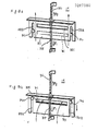
- a cover plate 33 is slidably attached on one side surface of duct plate 191 so as to be capable of obstructing the second suction opening 31. As shown in Fig. 8a, the cover plate 33 has a rectangular hole 331 which can be aligned with the second suction opening 31 to form an air flow-way.
- cover plate 33 The sliding motion of cover plate 33 is controlled by a guide mechanism, such as lateral slots in the plate 33, engaging pins 34 fixed on the duct plate 191. This determines the stopped position of the cover plate when it is pulled downwardly, thus ensuring alignment of hole 331 of cover plate 33 and second suction hole 31.
- a guide mechanism such as lateral slots in the plate 33, engaging pins 34 fixed on the duct plate 191.
- the recoil strength (F1) of drive spring 34 under normal temperature condition is determined to be lower than recoil strength (F2) of bias spring 35 (F1 ⁇ F2), therefore cover plate 33 is pulled upwardly by the bias spring 35. At that time, second suction opening 31 is fully covered by cover plate 33. Thus, refrigerated air is passed along the columns and returned to space 15 through the first suction opening 30. (This situation is shown in Fig. 8a.)
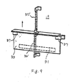
- cover plate 33 is hung on a drive spring 35 ⁇ formed of shape memory alloy, and pulled downwardly by a bias spring 36 ⁇ , as shown in Fig. 9, hole 331 on cover plate 33 can be omitted.
- the opening and closing of the second suction opening 31 is controlled by cover plate 33, in other words, when the second suction opening 31 is opened, cover plate 33 is totally removed from the second suction opening 31.
- the sliding motion of cover plate 33 may be guided by L-shaped brackets 37 attached to the duct plate 191.
- the opening and closing of the second suction opening 31 may be controlled by a cover plate 33 ⁇ hinged on a duct plate 191 as shown in Fig. 10.
- Cover plate 33 ⁇ is pushed against duct plate 191 to cover the opening of the second suction opening 31 by bias spring 36 ⁇ , and pulled by drive spring 35" formed of shape memory alloy to open the opening of second suction opening 31. Therefore, rotatable movement of cover plate 33 ⁇ is controlled due to difference of recoil strength between bias and drive springs 35 ⁇ and 36 ⁇ .
- Fig. 11 illustrates a modification of the air circulation control device in Figs. 6 and 7.
- sliding motion of cover plate 33 is directly controlled by difference of recoil strength between the drive and bias springs, but in this embodiment, cover plate 33 ⁇ is controlled by an air circulation control device 21 as shown in Figs. 3 and 4.
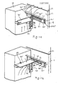
- a control lever 40 extends from a corner edge of baffle plate 22' toward duct plate 191. Control lever 40 is engaged with a horizontal flange 41 formed on the upper edge of a cover plate 33 ⁇ . Therefore, sliding motion of cover plate 33 ⁇ to control the opening and closing of second suction opening 31 depends upon pivoting of the baffle plate 22 ⁇ . This pivoting is controlled by the difference of recoil strength between drive and bias springs, as explained with reference to Figs. 5a and 5b. Therefore, if baffle plate 22 ⁇ is positioned parallel with air gap 20 to allow the refrigerated air flow, the second suction opening 31 is closed by cover plate 33 ⁇ . (This situation is shown in Fig. 11a.) At that time, merchandise stored on column 12 is fully refrigerated by refrigerating air passed among the column and along the air gap 20.
- the second suction opening 31 is opened to form the air by-pass way. (This situation is shown in Fig. 11b.) At that time, only merchandise stored on the lower half portion of column 12 is heated by heating air. Merchandise stored in the upper half portion of column 12 can be held at ambient temperature.
- the sliding motion of cover plate 33 ⁇ is guided by pins 34 and slits 331 ⁇ .
- movement of cover plate 33 ⁇ may be guided by a crank lever 45, as shown in Fig. 12.
- cover plate 33 ⁇ has a swing motion. Its moving range is restricted by a pair of pin elements 46.
- Fig. 13 illustrates a further modification of the air circulation control device in Figs. 3 and 4.
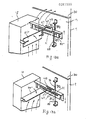
- the rotating operation of baffle plate 22 ⁇ to control the air flow passed through air gap 20 depends upon the sliding motion of a cover plate 33′′′ which is controlled by differences of recoil strength of bias and drive springs 35,36, as explained with reference to Figs. 8a and 8b.
- a control lever 47 projects from one edge corner of baffle plate 22 ⁇ toward duct plate 191. It engages in an elongate rectangular hole 48 formed in a projecting flange 49 of the cover plate 33′′′.
- cover plate 33′′′ is vertically slidable along the side surface of duct plate 191 due to change of recoil strength of bias and drive springs 35,36.
- cover plate 50 is disposed on one side surface of duct plate 191 to enabel rotating motion around a central fixed pin 51, and guided by a guide plate 52, as shown in Fig. 15. That is cover plate 50 is arc shaped and provided with a rectangular hole 501 to form an air by-pass way.
- Opposed spring elements 53,54 engage respective opposite edges of the cover plate 50. Therefore, cover plate 50 is rotated around fixed pin 51 in accordance with change of recoil strength of spring elements 53,54, one of the spring elements being formed of shape memory alloy.
Landscapes
- Physics & Mathematics (AREA)
- Engineering & Computer Science (AREA)
- General Physics & Mathematics (AREA)
- Chemical & Material Sciences (AREA)
- Combustion & Propulsion (AREA)
- Mechanical Engineering (AREA)
- Thermal Sciences (AREA)
- General Engineering & Computer Science (AREA)
- Automation & Control Theory (AREA)
- Control Of Vending Devices And Auxiliary Devices For Vending Devices (AREA)
Applications Claiming Priority (10)
| Application Number | Priority Date | Filing Date | Title |
|---|---|---|---|
| JP57894/87U | 1987-04-16 | ||
| JP1987057897U JPS63168580U (fr) | 1987-04-16 | 1987-04-16 | |
| JP1987057894U JPS63168577U (fr) | 1987-04-16 | 1987-04-16 | |
| JP57896/87U | 1987-04-16 | ||
| JP1987057895U JPS63168578U (fr) | 1987-04-16 | 1987-04-16 | |
| JP1987057896U JPS63168579U (fr) | 1987-04-16 | 1987-04-16 | |
| JP57897/87U | 1987-04-16 | ||
| JP57895/87U | 1987-04-16 | ||
| JP125169/87U | 1987-08-19 | ||
| JP1987125169U JPS6431470U (fr) | 1987-08-19 | 1987-08-19 |
Publications (2)
| Publication Number | Publication Date |
|---|---|
| EP0287390A2 true EP0287390A2 (fr) | 1988-10-19 |
| EP0287390A3 EP0287390A3 (fr) | 1990-01-17 |
Family
ID=27523412
Family Applications (1)
| Application Number | Title | Priority Date | Filing Date |
|---|---|---|---|
| EP88303420A Ceased EP0287390A3 (fr) | 1987-04-16 | 1988-04-15 | Machine de vente avec contrôle de température |
Country Status (3)
| Country | Link |
|---|---|
| US (1) | US4815302A (fr) |
| EP (1) | EP0287390A3 (fr) |
| KR (1) | KR960011507B1 (fr) |
Cited By (2)
| Publication number | Priority date | Publication date | Assignee | Title |
|---|---|---|---|---|
| CN102758960A (zh) * | 2012-07-31 | 2012-10-31 | 浙江大学 | 采用形状记忆合金材料的温度调控阀门 |
| ITVA20110034A1 (it) * | 2011-12-13 | 2013-06-14 | Whirlpool Co | Frigorifero domestico |
Families Citing this family (10)
| Publication number | Priority date | Publication date | Assignee | Title |
|---|---|---|---|---|
| US5374116A (en) * | 1993-04-28 | 1994-12-20 | Fawn Engineering Co. | Anti-condensation product viewing window for a vending machine |
| US6170285B1 (en) * | 1999-10-26 | 2001-01-09 | Crane Co. | Vending machine |
| US6378324B1 (en) * | 1999-10-26 | 2002-04-30 | Crane Co. | Thermally regulated storage container |
| US6910340B2 (en) * | 2002-04-16 | 2005-06-28 | Illinois Tool Works Inc. | Airflow control device |
| US7117689B2 (en) * | 2004-02-02 | 2006-10-10 | The Coca-Cola Company | Removable refrigeration cassette for a hot and cold vending machine |
| US20070289320A1 (en) * | 2006-06-15 | 2007-12-20 | Mohinder Singh Bhatti | Vapor compression AC system with evaporative cooler assisted evaporator |
| USD625125S1 (en) | 2009-02-13 | 2010-10-12 | Pepsico, Inc. | Cooler |
| JP2015046013A (ja) * | 2013-08-28 | 2015-03-12 | 富士電機株式会社 | 自動販売機 |
| CN107588593A (zh) * | 2017-10-13 | 2018-01-16 | 成都易住信息技术有限公司 | 一种基于网络支付的智能生鲜柜 |
| CN110335555B (zh) * | 2019-06-15 | 2021-06-18 | 义乌市航英科技有限公司 | 一种广告架 |
Family Cites Families (7)
| Publication number | Priority date | Publication date | Assignee | Title |
|---|---|---|---|---|
| US2825488A (en) * | 1956-06-18 | 1958-03-04 | Steelemade Inc | Vending machines |
| NL146597B (nl) * | 1964-09-14 | Muensterlaendische Margarine W | Vrieskast met koelaggregaat en gedwongen circulatie van de koellucht. | |
| DE1574263A1 (de) * | 1967-01-24 | 1971-11-18 | Tn Verkaufsautomaten Gmbh | Gekuehlter Selbstverkaeufer |
| JPS5663985U (fr) * | 1979-10-22 | 1981-05-29 | ||
| US4337892A (en) * | 1980-10-17 | 1982-07-06 | Werner Diermayer | Draft control arrangement for vent of combustion apparatus |
| US4676074A (en) * | 1984-06-21 | 1987-06-30 | The Coca-Cola Company | Refrigeration system for a counter-top or wall-mounted vending machine |
| US4663943A (en) * | 1985-08-12 | 1987-05-12 | Dyment Limited | Article display apparatus |
-
1988
- 1988-04-15 EP EP88303420A patent/EP0287390A3/fr not_active Ceased
- 1988-04-16 KR KR1019880004323A patent/KR960011507B1/ko not_active Expired - Fee Related
- 1988-04-18 US US07/182,737 patent/US4815302A/en not_active Expired - Fee Related
Cited By (3)
| Publication number | Priority date | Publication date | Assignee | Title |
|---|---|---|---|---|
| ITVA20110034A1 (it) * | 2011-12-13 | 2013-06-14 | Whirlpool Co | Frigorifero domestico |
| CN102758960A (zh) * | 2012-07-31 | 2012-10-31 | 浙江大学 | 采用形状记忆合金材料的温度调控阀门 |
| CN102758960B (zh) * | 2012-07-31 | 2013-11-13 | 浙江大学 | 采用形状记忆合金材料的温度调控阀门 |
Also Published As
| Publication number | Publication date |
|---|---|
| EP0287390A3 (fr) | 1990-01-17 |
| KR880013097A (ko) | 1988-11-30 |
| US4815302A (en) | 1989-03-28 |
| KR960011507B1 (ko) | 1996-08-23 |
Similar Documents
| Publication | Publication Date | Title |
|---|---|---|
| US7254958B2 (en) | Refrigerator | |
| EP0287390A2 (fr) | Machine de vente avec contrôle de température | |
| EP0872696A2 (fr) | Réfrigérateur | |
| EP0872697A2 (fr) | Réfrigérateur | |
| US20200011591A1 (en) | Refrigerator | |
| US7497353B2 (en) | Displaceable barrier | |
| US6044659A (en) | Refrigerator having a device for opening/closing cool air discharge ports | |
| EP0893660B1 (fr) | Réfrigérateur | |
| KR100482001B1 (ko) | 냉기의 토출위치를 변경할 수 있는 토출부재를 구비한 냉장고 | |
| EP0893659A2 (fr) | Réfrigérateur | |
| JP7248948B2 (ja) | 自動販売機 | |
| KR102892227B1 (ko) | 냉장고 | |
| CN101097643B (zh) | 自动售货机 | |
| JPS6033494Y2 (ja) | 冷温切換式自動販売機の空気循環制御機構 | |
| JPH0431654Y2 (fr) | ||
| JP2505890B2 (ja) | 自動販売機 | |
| JP3928283B2 (ja) | 自動販売機 | |
| JP2000113302A (ja) | 自動販売機 | |
| JP7441631B2 (ja) | 冷却貯蔵庫 | |
| JP3008639B2 (ja) | バックドア付きリーチイン形冷蔵ショーケース | |
| KR200161927Y1 (ko) | 냉장고 | |
| JPH087502Y2 (ja) | 自動販売機の冷却加熱切替装置 | |
| JP2003346238A (ja) | 自動販売機のサーペンタイン式商品収納ラック | |
| JPH03109695A (ja) | 自動販売機 | |
| JP3497960B2 (ja) | 自動販売機のサーペンタイン式商品収納棚 |
Legal Events
| Date | Code | Title | Description |
|---|---|---|---|
| PUAI | Public reference made under article 153(3) epc to a published international application that has entered the european phase |
Free format text: ORIGINAL CODE: 0009012 |
|
| AK | Designated contracting states |
Kind code of ref document: A2 Designated state(s): DE GB IT |
|
| PUAL | Search report despatched |
Free format text: ORIGINAL CODE: 0009013 |
|
| AK | Designated contracting states |
Kind code of ref document: A3 Designated state(s): DE GB IT |
|
| 17P | Request for examination filed |
Effective date: 19900319 |
|
| 17Q | First examination report despatched |
Effective date: 19920330 |
|
| STAA | Information on the status of an ep patent application or granted ep patent |
Free format text: STATUS: THE APPLICATION HAS BEEN REFUSED |
|
| 18R | Application refused |
Effective date: 19930808 |