EP0287433B1 - Festhaltevorrichtung für Müllbehälter - Google Patents
Festhaltevorrichtung für Müllbehälter Download PDFInfo
- Publication number
- EP0287433B1 EP0287433B1 EP19880400824 EP88400824A EP0287433B1 EP 0287433 B1 EP0287433 B1 EP 0287433B1 EP 19880400824 EP19880400824 EP 19880400824 EP 88400824 A EP88400824 A EP 88400824A EP 0287433 B1 EP0287433 B1 EP 0287433B1
- Authority
- EP
- European Patent Office
- Prior art keywords
- suction cup
- holding device
- lifting mechanism
- container
- lifting
- Prior art date
- Legal status (The legal status is an assumption and is not a legal conclusion. Google has not performed a legal analysis and makes no representation as to the accuracy of the status listed.)
- Expired - Lifetime
Links
- 230000007246 mechanism Effects 0.000 title claims description 35
- 239000010813 municipal solid waste Substances 0.000 claims description 6
- 230000006835 compression Effects 0.000 claims description 4
- 238000007906 compression Methods 0.000 claims description 4
- 235000003434 Sesamum indicum Nutrition 0.000 description 4
- 244000000231 Sesamum indicum Species 0.000 description 4
- 206010003830 Automatism Diseases 0.000 description 1
- 230000003416 augmentation Effects 0.000 description 1
- 238000006073 displacement reaction Methods 0.000 description 1
- 239000010791 domestic waste Substances 0.000 description 1
- 230000000694 effects Effects 0.000 description 1
- 230000014509 gene expression Effects 0.000 description 1
- 238000012986 modification Methods 0.000 description 1
- 230000004048 modification Effects 0.000 description 1
- 239000002991 molded plastic Substances 0.000 description 1
- 230000000717 retained effect Effects 0.000 description 1
- 239000002699 waste material Substances 0.000 description 1
Images
Classifications
-
- B—PERFORMING OPERATIONS; TRANSPORTING
- B65—CONVEYING; PACKING; STORING; HANDLING THIN OR FILAMENTARY MATERIAL
- B65F—GATHERING OR REMOVAL OF DOMESTIC OR LIKE REFUSE
- B65F3/00—Vehicles particularly adapted for collecting refuse
- B65F3/02—Vehicles particularly adapted for collecting refuse with means for discharging refuse receptacles thereinto
- B65F3/04—Linkages, pivoted arms, or pivoted carriers for raising and subsequently tipping receptacles
-
- B—PERFORMING OPERATIONS; TRANSPORTING
- B65—CONVEYING; PACKING; STORING; HANDLING THIN OR FILAMENTARY MATERIAL
- B65F—GATHERING OR REMOVAL OF DOMESTIC OR LIKE REFUSE
- B65F3/00—Vehicles particularly adapted for collecting refuse
- B65F3/02—Vehicles particularly adapted for collecting refuse with means for discharging refuse receptacles thereinto
- B65F2003/0223—Vehicles particularly adapted for collecting refuse with means for discharging refuse receptacles thereinto the discharging means comprising elements for holding the receptacle
- B65F2003/0236—Suction or vacuum heads
-
- B—PERFORMING OPERATIONS; TRANSPORTING
- B65—CONVEYING; PACKING; STORING; HANDLING THIN OR FILAMENTARY MATERIAL
- B65F—GATHERING OR REMOVAL OF DOMESTIC OR LIKE REFUSE
- B65F3/00—Vehicles particularly adapted for collecting refuse
- B65F3/02—Vehicles particularly adapted for collecting refuse with means for discharging refuse receptacles thereinto
- B65F2003/0223—Vehicles particularly adapted for collecting refuse with means for discharging refuse receptacles thereinto the discharging means comprising elements for holding the receptacle
- B65F2003/024—Means for locking the rim
Definitions
- the present invention relates to a retaining device for the corresponding refuse containers in the preamble of claim 1.
- a retaining device for the corresponding refuse containers in the preamble of claim 1.
- Such a device is known from DE-A-2515929.
- the so-called "frontal grip” type has developed more than others; they include a comb on which one or two containers are hung by their flange which is then trapped by clamps moved by jacks. During the rotation phase of the container for emptying into the hopper of the bucket, it is driven by a stopper mounted on the arms of the lifting mechanism.
- the object of the present invention is to provide a retaining device of the kind specified above which ensures a certain flexibility of the assembly, which can be used regardless of the type of container to be emptied and which is less heavy and less expensive than the devices currently existing.
- this suction cup retaining device makes it possible to make the container to be emptied and the lifting mechanism integral with one another by simply creating a vacuum inside the suction cup. Then just remove this depression to release the container.
- the flexibility of the lips of the suction cup leaves the container with a low amplitude in its final tilting phase, to take account only of the play of the moving parts. In this way, the flange of the container is not subjected to the violent forces that are observed when using known systems.
- the suction cup specified above is elastically mounted on the lifting mechanism of the bucket, and this, preferably, by means of a coaxial compression spring . This provision allows the tilting effort to be taken up by the buffer of the container lifter, and not by the suction cup.
- the suction cup specified above is mounted in an articulated manner on the mechanism for lifting the bucket, and this, preferably, by means of a Cardan joint.
- This joint allows the suction cup to adapt to the walls of the molded plastic containers whose clearance angle varies between 0 and 4 °.
- the dimensions and the position of the retaining device according to the present invention are such that in the absence of any vacuum in the specified suction cup above, there is a play, of a few millimeters for example, between the stopper of the lifting mechanism and the container to be emptied when the latter has just been hung on the comb of the lifting mechanism.
- the vacuum of the suction cup, and therefore its attachment to the container to be emptied is caused only a few centimeters after the start of the handling or lifting phase.
- the retaining device according to the invention comprises a suction cup on each arm of the bucket lifting mechanism.
- this retaining device can take place manually, it can also be achieved by means of automatically creating and removing the vacuum in the suction cup of the retaining device when the mechanism for lifting the bucket reaches a predetermined point of its course.
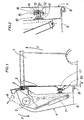
- Figure 1 shows a garbage container 1 hooked by its flange 2 on the comb 3 of a lifting mechanism which is generally designated by the reference 4, which is only shown schematically, and which, by tilting by about 180 ° around a horizontal axis 5, in the direction of the arrows F, brings the container 1, upside down, above the hopper for loading a bucket not shown.
- a clamp 6 rotates around the axis 5, in the direction of the arrow F ′, under the effect of a hydraulic cylinder 7, to bring it from its open position, in broken lines in FIG. 1, to its closed position in solid lines in which it traps over the flange 2.
- a stopper 8 turned towards the container 1, is mounted on the end lower of the lifting arms 9 of the mechanism 4, which are generally two in number.
- a retaining device is fixed to each lifting arm 9 extending towards the container 1.
- this device 10 comprises a compression spring 11 which is fixed to the corresponding lifting arm 9 and the free end 12 of which is articulated by a horizontal axis 13 on a vertical journal 14.
- the latter is articulated by an axis 15 in a yoke 16, the sole of which carries, on the side of the container 1, a suction cup 17 connected to a pneumatic system, not shown, making it possible to create a vacuum there and to eliminate it.
- the free end 12 of the spring 11 is connected to the suction cup 17 by a cardan joint formed by the pin 14 and the axes 13 and 15.
- the operating mode of the device which has just been described is as follows: the container 1 is hooked as usual by its flange 2 on the comb 3 of the lifting mechanism 4, and it comes to bear on the suction cup 17, as it has been shown in solid lines in FIG. 1, the dimensions and the position of the retaining device 10 being such that the container 1 is spaced from the stopper 8 by a distance d equal to a few millimeters, 2 to 10 for example .
- the suction cup 17 progressively collapses under the weight of the container, and the latter ends up approaching the stopper 8, as is can be seen in FIG. 2 and, in broken lines, in FIG. 1.
- a vacuum is then applied inside the suction cup 17 which crashes on the container 1, a deformation of the compression spring 11 which compensates for the displacement of the articulation 13, 14, 15.
- the raising of the container 1 continues, however it is retained on the lifting mechanism 4, bearing on the stopper 8, by the suction device according to the invention, 10.
- the vacuuming of the suction cup 17 and its return to atmospheric pressure can be carried out by means of a manual control, but it is easy to subject these operations to the movements of the lifting mechanism 4 which, for example, can come in taken with a trigger stop at a given point in its course.
- Such automatism is within the reach of any person skilled in the art, and it will therefore not be described here in more detail.
- the lifting mechanism could have a configuration different from that comprising lifting arms 9, and that several containers could be hung simultaneously on the comb 3 of the lifting mechanism 4.
Landscapes
- Engineering & Computer Science (AREA)
- Mechanical Engineering (AREA)
- Refuse-Collection Vehicles (AREA)
Claims (8)
Applications Claiming Priority (2)
| Application Number | Priority Date | Filing Date | Title |
|---|---|---|---|
| FR8705389 | 1987-04-15 | ||
| FR8705389A FR2614010B1 (fr) | 1987-04-15 | 1987-04-15 | Dispositif de retenue pour les conteneurs a ordures |
Publications (2)
| Publication Number | Publication Date |
|---|---|
| EP0287433A1 EP0287433A1 (de) | 1988-10-19 |
| EP0287433B1 true EP0287433B1 (de) | 1991-06-19 |
Family
ID=9350176
Family Applications (1)
| Application Number | Title | Priority Date | Filing Date |
|---|---|---|---|
| EP19880400824 Expired - Lifetime EP0287433B1 (de) | 1987-04-15 | 1988-04-06 | Festhaltevorrichtung für Müllbehälter |
Country Status (3)
| Country | Link |
|---|---|
| EP (1) | EP0287433B1 (de) |
| DE (1) | DE3863309D1 (de) |
| FR (1) | FR2614010B1 (de) |
Families Citing this family (7)
| Publication number | Priority date | Publication date | Assignee | Title |
|---|---|---|---|---|
| DE4091845T (de) * | 1989-10-12 | 1993-02-18 | ||
| NZ252921A (en) * | 1992-06-15 | 1996-07-26 | Macdonald Johnston Eng | Grab for use in emptying refuse bins: articulated arms connected by flexible belt |
| WO1994007773A1 (de) * | 1992-10-05 | 1994-04-14 | Wirth Gallo Messtechnik Ag | Wägevorrichtung für schüttgüter, insbesondere für müll |
| WO1994020392A1 (en) * | 1993-03-11 | 1994-09-15 | Formark Pty Ltd | Clamp for bin lifter |
| DE9414479U1 (de) * | 1994-09-07 | 1994-10-27 | FAUN Umwelttechnik AG, 90411 Nürnberg | Hubvorrichtung für ein in ein Entsorgungsfahrzeug zu entleerendes Müll- und/oder Wertstoff-Gefäß |
| DE19655095C2 (de) * | 1996-01-29 | 2002-03-07 | Faun Umwelttechnik Gmbh & Co | Müllsammelfahrzeug mit zwei um eine Querachse schwenkbar am Fahrgestell gelagerten Bügeln einer Hub-Kipp-Vorrichtung |
| DE102007042347A1 (de) * | 2007-09-06 | 2009-03-12 | Environmental Solutions Europe Holding B.V. | Vorrichtung und Verfahren zum Versetzen eines Behälters in Schwingungen sowie zum Entleeren von Behältern |
Family Cites Families (4)
| Publication number | Priority date | Publication date | Assignee | Title |
|---|---|---|---|---|
| DE2146653C3 (de) * | 1971-09-17 | 1980-03-20 | Sulo Eisenwerk Streuber & Lohmann Gmbh & Co Kg, 4900 Herford | Einrichtung zum Entleeren von im wesentlichen einen quadratischen oder rechteckigen Grundriß aufweisenden GroOraum-Müllbehältern |
| DE2515929C2 (de) * | 1975-04-11 | 1985-12-12 | Zöller-Kipper GmbH, 6500 Mainz | Vorrichtung zum Entleeren von Müllbehältern |
| DE2558466C2 (de) * | 1975-12-23 | 1984-06-07 | Walter 5779 Visbeck Arndt | Hubkipp- oder Kippvorrichtung zum Entleeren von Müllbehältern unterschiedlicher Größe |
| AT386583B (de) * | 1982-03-16 | 1988-09-12 | Zoeller Kipper | Vorrichtung zum entleeren von behaeltern in einen sammelbehaelter |
-
1987
- 1987-04-15 FR FR8705389A patent/FR2614010B1/fr not_active Expired - Fee Related
-
1988
- 1988-04-06 DE DE8888400824T patent/DE3863309D1/de not_active Expired - Fee Related
- 1988-04-06 EP EP19880400824 patent/EP0287433B1/de not_active Expired - Lifetime
Also Published As
| Publication number | Publication date |
|---|---|
| FR2614010B1 (fr) | 1992-04-24 |
| FR2614010A1 (fr) | 1988-10-21 |
| EP0287433A1 (de) | 1988-10-19 |
| DE3863309D1 (de) | 1991-07-25 |
Similar Documents
| Publication | Publication Date | Title |
|---|---|---|
| EP1081063B1 (de) | Vorrichtung zum automatisch durch Schwerkraft Verriegeln und Entriegeln des Deckels eines Behälters sowie Behälter mit einer derartigen Vorrichtung | |
| EP0287433B1 (de) | Festhaltevorrichtung für Müllbehälter | |
| EP0774424B1 (de) | Müllsammelbehälter mit Mitteln zum Abbremsen der Schliessbewegung des Deckels | |
| FR2522471A1 (fr) | Vehicule de transport de recolte a dechargement automatique | |
| FR2752792A1 (fr) | Boite a gants notamment pour vehicules automobiles | |
| FR2728136A1 (fr) | Bac de ramassage a coque de vidange pour tondeuse autoportee a support de bacs amovibles, et tondeuse comportant un tel bac | |
| EP3789320B1 (de) | Verfahren zum ausschütten des inhalts eines behälters | |
| FR2508421A1 (fr) | Dispositif pour la collecte de sacs-poubelles, de recipients de dechets, ou analogues | |
| EP3812302B1 (de) | Tierkörperbeseitigungsbehälter mit automatischer rückführung | |
| EP1707437B1 (de) | System zum Entriegeln der Heckklappe eines Kippers | |
| FR3102341A1 (fr) | Bac d’équarrissage à rétablissement automatique | |
| EP3766805B1 (de) | Dichter deckel für abfallsammelbehälter | |
| EP3477030A1 (de) | Hilfsvorrichtung für ein öffnungselement eines fahrzeugs | |
| EP0278808B1 (de) | Mit zwei Verdichtungseinrichtungen versehener Müllbehälter | |
| FR3032432B1 (fr) | "systeme de blocage du dispositif de maintien du sac d'une poubelle" | |
| EP0542600B1 (de) | Anhakungsvorrichtung für Förderungsvorrichtung von trapezförmigen Behältern | |
| BE403869A (de) | ||
| FR2763783A1 (fr) | Tondeuse a conducteur porte comprenant notamment un collecteur pour l'herbe coupee | |
| FR2739346A1 (fr) | Dispositif de recuperation du materiau constitutif de la vitre d'un ouvrant de vehicule automobile tel qu'un hayon | |
| FR2600045A1 (fr) | Dispositif de compactage pour benne a dechets. | |
| FR2479124A1 (fr) | Dispositif permettant l'equipement de tracteurs agricoles pour la sylviculture | |
| FR3122872A1 (fr) | Bac de collecte de déchets à double couvercle muni d’un dispositif de retenue des couvercles amélioré | |
| CH579490A5 (en) | Container for bulk holding of rubbish and waste - has one end forming flap power operated to swing into interior and compress contents | |
| EP1505008A1 (de) | Müllsammelbehälter | |
| FR2763318A1 (fr) | Leves-conteneurs a secteurs mobiles de retenue et bennes equipees de tels leves-conteneurs |
Legal Events
| Date | Code | Title | Description |
|---|---|---|---|
| PUAI | Public reference made under article 153(3) epc to a published international application that has entered the european phase |
Free format text: ORIGINAL CODE: 0009012 |
|
| AK | Designated contracting states |
Kind code of ref document: A1 Designated state(s): BE CH DE ES GB IT LI NL SE |
|
| 17P | Request for examination filed |
Effective date: 19880908 |
|
| 17Q | First examination report despatched |
Effective date: 19900709 |
|
| GRAA | (expected) grant |
Free format text: ORIGINAL CODE: 0009210 |
|
| AK | Designated contracting states |
Kind code of ref document: B1 Designated state(s): BE CH DE ES GB IT LI NL SE |
|
| PG25 | Lapsed in a contracting state [announced via postgrant information from national office to epo] |
Ref country code: IT Free format text: LAPSE BECAUSE OF FAILURE TO SUBMIT A TRANSLATION OF THE DESCRIPTION OR TO PAY THE FEE WITHIN THE PRESCRIBED TIME-LIMIT;WARNING: LAPSES OF ITALIAN PATENTS WITH EFFECTIVE DATE BEFORE 2007 MAY HAVE OCCURRED AT ANY TIME BEFORE 2007. THE CORRECT EFFECTIVE DATE MAY BE DIFFERENT FROM THE ONE RECORDED. Effective date: 19910619 Ref country code: ES Free format text: THE PATENT HAS BEEN ANNULLED BY A DECISION OF A NATIONAL AUTHORITY Effective date: 19910619 Ref country code: NL Effective date: 19910619 Ref country code: GB Effective date: 19910619 Ref country code: SE Effective date: 19910619 |
|
| REF | Corresponds to: |
Ref document number: 3863309 Country of ref document: DE Date of ref document: 19910725 |
|
| NLV1 | Nl: lapsed or annulled due to failure to fulfill the requirements of art. 29p and 29m of the patents act | ||
| GBV | Gb: ep patent (uk) treated as always having been void in accordance with gb section 77(7)/1977 [no translation filed] | ||
| PLBE | No opposition filed within time limit |
Free format text: ORIGINAL CODE: 0009261 |
|
| STAA | Information on the status of an ep patent application or granted ep patent |
Free format text: STATUS: NO OPPOSITION FILED WITHIN TIME LIMIT |
|
| PG25 | Lapsed in a contracting state [announced via postgrant information from national office to epo] |
Ref country code: CH Effective date: 19920430 Ref country code: LI Effective date: 19920430 Ref country code: BE Effective date: 19920430 |
|
| 26N | No opposition filed | ||
| BERE | Be: lapsed |
Owner name: SEMAT Effective date: 19920430 |
|
| REG | Reference to a national code |
Ref country code: CH Ref legal event code: PL |
|
| PGFP | Annual fee paid to national office [announced via postgrant information from national office to epo] |
Ref country code: DE Payment date: 19980323 Year of fee payment: 11 |
|
| PG25 | Lapsed in a contracting state [announced via postgrant information from national office to epo] |
Ref country code: DE Free format text: LAPSE BECAUSE OF NON-PAYMENT OF DUE FEES Effective date: 20000201 |