EP0287453B1 - Elektrische Verbindung aus Bimetall und Verfahren zur Herstellung einer solchen Verbindung - Google Patents
Elektrische Verbindung aus Bimetall und Verfahren zur Herstellung einer solchen Verbindung Download PDFInfo
- Publication number
- EP0287453B1 EP0287453B1 EP88400877A EP88400877A EP0287453B1 EP 0287453 B1 EP0287453 B1 EP 0287453B1 EP 88400877 A EP88400877 A EP 88400877A EP 88400877 A EP88400877 A EP 88400877A EP 0287453 B1 EP0287453 B1 EP 0287453B1
- Authority
- EP
- European Patent Office
- Prior art keywords
- electrical connection
- connection according
- component
- components
- bimetallic
- Prior art date
- Legal status (The legal status is an assumption and is not a legal conclusion. Google has not performed a legal analysis and makes no representation as to the accuracy of the status listed.)
- Expired - Lifetime
Links
- 238000004519 manufacturing process Methods 0.000 title claims description 11
- 230000001681 protective effect Effects 0.000 claims abstract description 32
- 230000007704 transition Effects 0.000 claims abstract description 19
- 239000007769 metal material Substances 0.000 claims abstract description 16
- 238000000034 method Methods 0.000 claims description 9
- 230000000694 effects Effects 0.000 claims description 5
- 239000000463 material Substances 0.000 claims description 5
- 230000000295 complement effect Effects 0.000 claims description 3
- 239000000470 constituent Substances 0.000 claims description 3
- 239000011810 insulating material Substances 0.000 claims description 2
- 238000000465 moulding Methods 0.000 claims description 2
- 238000007493 shaping process Methods 0.000 claims description 2
- 238000002788 crimping Methods 0.000 claims 1
- 238000007373 indentation Methods 0.000 description 21
- 229910052802 copper Inorganic materials 0.000 description 13
- 239000010949 copper Substances 0.000 description 13
- RYGMFSIKBFXOCR-UHFFFAOYSA-N Copper Chemical compound [Cu] RYGMFSIKBFXOCR-UHFFFAOYSA-N 0.000 description 12
- 229910052782 aluminium Inorganic materials 0.000 description 12
- XAGFODPZIPBFFR-UHFFFAOYSA-N aluminium Chemical compound [Al] XAGFODPZIPBFFR-UHFFFAOYSA-N 0.000 description 12
- 229910000838 Al alloy Inorganic materials 0.000 description 7
- 230000035515 penetration Effects 0.000 description 6
- 229910000881 Cu alloy Inorganic materials 0.000 description 5
- 239000002131 composite material Substances 0.000 description 5
- 229910052751 metal Inorganic materials 0.000 description 5
- 239000002184 metal Substances 0.000 description 5
- 229920002994 synthetic fiber Polymers 0.000 description 5
- 239000003795 chemical substances by application Substances 0.000 description 4
- 230000008595 infiltration Effects 0.000 description 4
- 238000001764 infiltration Methods 0.000 description 4
- 238000002347 injection Methods 0.000 description 3
- 239000007924 injection Substances 0.000 description 3
- 150000002739 metals Chemical class 0.000 description 3
- AZDRQVAHHNSJOQ-UHFFFAOYSA-N alumane Chemical group [AlH3] AZDRQVAHHNSJOQ-UHFFFAOYSA-N 0.000 description 2
- 230000008901 benefit Effects 0.000 description 2
- 230000015572 biosynthetic process Effects 0.000 description 2
- 239000011248 coating agent Substances 0.000 description 2
- 238000000576 coating method Methods 0.000 description 2
- 239000004020 conductor Substances 0.000 description 2
- 230000007797 corrosion Effects 0.000 description 2
- 238000005260 corrosion Methods 0.000 description 2
- 238000005520 cutting process Methods 0.000 description 2
- 230000006378 damage Effects 0.000 description 2
- 238000009776 industrial production Methods 0.000 description 2
- 239000003595 mist Substances 0.000 description 2
- 238000011084 recovery Methods 0.000 description 2
- XLYOFNOQVPJJNP-UHFFFAOYSA-N water Substances O XLYOFNOQVPJJNP-UHFFFAOYSA-N 0.000 description 2
- 238000003466 welding Methods 0.000 description 2
- FAPWRFPIFSIZLT-UHFFFAOYSA-M Sodium chloride Chemical compound [Na+].[Cl-] FAPWRFPIFSIZLT-UHFFFAOYSA-M 0.000 description 1
- 230000016571 aggressive behavior Effects 0.000 description 1
- 230000032683 aging Effects 0.000 description 1
- 229910045601 alloy Inorganic materials 0.000 description 1
- 239000000956 alloy Substances 0.000 description 1
- 230000015556 catabolic process Effects 0.000 description 1
- 230000003749 cleanliness Effects 0.000 description 1
- 238000004891 communication Methods 0.000 description 1
- 150000001879 copper Chemical class 0.000 description 1
- 238000005336 cracking Methods 0.000 description 1
- 238000006731 degradation reaction Methods 0.000 description 1
- 230000006866 deterioration Effects 0.000 description 1
- 230000008034 disappearance Effects 0.000 description 1
- 238000009434 installation Methods 0.000 description 1
- 238000009413 insulation Methods 0.000 description 1
- 229910001092 metal group alloy Inorganic materials 0.000 description 1
- 210000000056 organ Anatomy 0.000 description 1
- 239000003973 paint Substances 0.000 description 1
- 229920000915 polyvinyl chloride Polymers 0.000 description 1
- 239000004800 polyvinyl chloride Substances 0.000 description 1
- 230000000750 progressive effect Effects 0.000 description 1
- 230000002035 prolonged effect Effects 0.000 description 1
- 239000011241 protective layer Substances 0.000 description 1
- 150000003839 salts Chemical class 0.000 description 1
- 238000002791 soaking Methods 0.000 description 1
- 239000011780 sodium chloride Substances 0.000 description 1
- 125000006850 spacer group Chemical group 0.000 description 1
- 238000003892 spreading Methods 0.000 description 1
- 230000002459 sustained effect Effects 0.000 description 1
- 239000002966 varnish Substances 0.000 description 1
- 125000000391 vinyl group Chemical group [H]C([*])=C([H])[H] 0.000 description 1
- 229920002554 vinyl polymer Polymers 0.000 description 1
- 230000003313 weakening effect Effects 0.000 description 1
Images
Classifications
-
- H—ELECTRICITY
- H01—ELECTRIC ELEMENTS
- H01R—ELECTRICALLY-CONDUCTIVE CONNECTIONS; STRUCTURAL ASSOCIATIONS OF A PLURALITY OF MUTUALLY-INSULATED ELECTRICAL CONNECTING ELEMENTS; COUPLING DEVICES; CURRENT COLLECTORS
- H01R4/00—Electrically-conductive connections between two or more conductive members in direct contact, i.e. touching one another; Means for effecting or maintaining such contact; Electrically-conductive connections having two or more spaced connecting locations for conductors and using contact members penetrating insulation
- H01R4/58—Electrically-conductive connections between two or more conductive members in direct contact, i.e. touching one another; Means for effecting or maintaining such contact; Electrically-conductive connections having two or more spaced connecting locations for conductors and using contact members penetrating insulation characterised by the form or material of the contacting members
- H01R4/62—Connections between conductors of different materials; Connections between or with aluminium or steel-core aluminium conductors
Definitions
- the present invention relates generally to bi-metallic electrical connections, that is to say electrical connections using, applied to one another, a first component of metallic material conducting the electric current d a first type, copper or copper alloy for example, and a second component in metallic material conducting the electric current of a second type different from the first, aluminum or aluminum alloy for example.
- Such bi-metallic electrical connections occur more and more frequently on electrical networks, for example for the connection to a bare aluminum or aluminum alloy cable of any connection member made of copper or copper alloy suitable for connection of 'any electrical device, or, for the establishment of an electrical connection between two bare cables, one in copper or copper alloy and the other in aluminum or aluminum alloy.
- the problem in this case is that the voltaic effect between the two different metals or metal alloys in contact, catalyzed by ambient humidity more or less conductive of the electric current, especially in a marine environment, and / or amplified by l corroding effect of possible atmospheric agents can jeopardize the electrical performance of such a bi-metallic electrical connection, and / or cause its mechanical weakening, or even destruction.
- a copper strip and an aluminum strip are rolled together, which leads to intimate adhesion between these metals, and the composite strip thus obtained receives on each of its faces a conductor of the same metal as this one.
- a first device consists in applying to this section an inert product, such as paint, varnish, or the like, capable of protecting it against humidity.
- a second device consists in providing the strip with raised edges or gutters capable of preventing more or less polluted rainwater from flowing from its copper face to its aluminum face, such runoff being of a nature, by the wet electrolytic chain which it implies, to cause in the short term the almost total disappearance of this aluminum face.
- this device cannot be suitable where the direction in which the rain is sprinkled is random, or where a mist, and in particular a salt mist, is liable to be established, and the same applies to the laying instructions. , always more or less respected, consisting in recommending a copper face installation below.
- the two metal components concerned are assembled to one another by the industrial process known as "friction welding" consisting in applying under pressure one of these components to the other while rotating it. around an axis in contact with it.
- a third provision applicable in particular to lugs, and it is substantially to a process of this kind that document FR-A-2,006,123 relates, it is proceeded to the introduction, by force, of a section of copper tube in the boundary hole of an aluminum terminal, and to the progressive shaping, by successive strikes, of this copper tube, so that, folded over the main faces of the aluminum terminal at the outlet of the boundary hole thereof, it forms on these faces of the support areas in copper.
- the present invention generally relates to a provision capable of obtaining, under industrial production conditions that are both simple and inexpensive, bi-metallic electrical connections advantageously reliable over time.
- the present invention firstly relates to a bi-metallic electrical connection of the kind comprising, on the one hand, applied to each other, a component of metallic material conducting the electric current of a first type and said below for simple convenience as a contact component and a component made of metallic material conducting the electric current of a second type different from the first and hereinafter said for simple convenience as a support component, and, on the other hand , a protective sheath which leaves free access to at least a portion of the surface of the contact component, and which is engaged with at least part of the support component, covering the edge of the transition zone through which said components are applied to each other, this electrical connection being generally characterized by that, constituted by a washer or a plate, and thereby projecting locally on the support component, the contact component is embedded by its edge in the protective sheath; it also relates to a process specific to the production of such a bi-metallic electrical connection.
- the transition zone between the two components used preferably has a form nesting from one to the other of these, this form nesting being for example due to the fact that any one of these components projecting at least one indentation and that, by this indentation, it is engaged with at least one recess recessed in a complementary manner on the other.
- the recess (s) thus presented in hollow one of the components results (s) from forming under pressure by the corresponding indentation (s) of the other of these components during application. to each other of these.
- the protective sheath used which is preferably made of a material inert with respect to atmospheric agents and insulating with respect to electric current, is overmolded.
- the production method according to the invention is generally characterized in that it consists in applying under pressure to each other two components, one of which is made of metallic material conducting the current. electric of a first type while the other is made of metallic material conducting the electric current of a second type different from the first, and of which one has at least one indentation on its contact face with the other, and overmolding a protective sheath on the assembly, which leaves free access to at least a portion of the surface of one of said components, and which is engaged with at least part of the other of said components component, by covering the edge of the transition zone by which said components are applied to each other.
- the bi-metallic electrical connection according to the invention also advantageously has no zone of mechanical embrittlement, and, in particular, it is insensitive to vibrations.
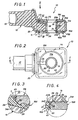
- FIGS. 1 to 7 illustrate, by way of example, the application of the invention to the production of a terminal 10.
- this terminal 10 comprises, as a basic component, a body 11 formed, on the one hand, of a barrel 12, which, hollowed out by a blind internal channel 13 over at least part of its length at from its free end, is tubular, and is thus suitable for being crimped on a bare electrical cable or on the stripped end of an insulated electrical cable, and, on the other hand, a connection ring 14, which , perforated with a terminal hole 15, is, for example intended, for its part, to be clamped on a connection terminal of any electrical apparatus.
- connection ring 14 is in the general form of a generally quadrangular contour plate, and in practice square, with rounded angles, with its boundary hole 15, which, disposed in its zone central, extends substantially perpendicular to its main faces 16A, 16B, one upper, the other lower.
- these main faces 16A, 16B which are parallel to each other, are generally flat and smooth.
- connection ring 14 is offset transversely relative to the axis of the tubular barrel 12 of which it is integral, the median plane intermediate between its main faces 16A, 16B extending away from this axis, in parallel to this one.
- the body 11 thus formed of such a tubular barrel 12 and of a connection ring 14 is made in one piece, for example by stamping, in a metallic material conducting the electric current.
- the terminal 10 having such a body 11 as its basic component, two bi-metallic electrical connections 18A, 18B.
- these bi-metallic electrical connections 18A, 18B are of the type comprising, applied to one another, and according to methods explained in more detail later, a component made of metallic material conducting the electrical current of a first type, and a component of metallic material conducting the electric current of a second type different from the first.
- a washer 19A, 19B is embedded by its edge T in a protective sheath 20, which leaves free access to at least a portion of its surface, and which is engaged with at least one part of the other of said components, hereinafter said simply for convenience, as a support component, and this is in practice the connection ring 14, covering the edge 22A, 22B of the transition zone 23A, 23B by which said components are applied to one another.
- the two bi-metallic electrical connections 18A, 18B according to the invention each comprise, as support component, the connection ring 14 of this terminal 10, and, as a contact component, a washer 19A, 19B, which is applied to the corresponding main face 16A, 16B of this connection ring 14, around the terminal hole 15 thereof.
- each of the washers 19A, 19B thus implemented has, protruding on its underside, or interior, along its internal periphery, a rim flange 24, by which, according to conditions explained more in detail later, it is engaged with the terminal hole 15 of the connection ring 14.
- a chamfer 25 cuts the internal periphery of these washers 19A, 19B, at the outlet of their central opening 26 on their upper, or outer, face.
- connection ring 14 is made of a metallic material conducting the electric current of a first type, and for example of aluminum or aluminum alloy, as indicated above, the washers 19A, 19B are made of a metallic conductive material electric current of a second type, different from the previous one.
- These include, for example, copper or copper alloy washers.
- the transition zone 23A, 23B between the two components which constitutes, for each of the bi-metallic electrical connections 18A, 18B, a washer 19A, 19B, on the one hand, and the ring of connection 14, on the other hand, has a form nesting from one to the other of these components.
- this imbrication of shape is due to the fact that any one of these components has at least one indentation 28 projecting, and that, by this indentation 28, it is engaged with a housing 29 recessed in a complementary manner on the other of said components.
- the housing 29 present in hollow on one of the components results from a forming ensured by the corresponding indentation 28 of the other of the components during the application to one another of these components.
- the component which projects at least one indentation 28 is therefore in practice the component whose constituent material is the hardest.
- each of these washers 19A, 19B has, effectively, projecting on its underside, or interior, and arranged annularly around its central opening 26, several concentric indentations 28.
- these indentations 28, which are identical to each other, are three in number, and they are ribs with a triangular transverse profile.
- That which is of smaller diameter is arranged in the vicinity of the corresponding flange 24, at a distance therefrom.
- each of the washers 19A, 19B left free by the protective sheath 20 is made up of the entire upper or outer surface of such a washer 19A, 19B.
- the washers 19A, 19B have, circularly, on their edge, a chamfer 30.
- This chamfer 30 belongs to a conical surface which goes by converging away from the connection ring 14.
- the washers 19A, 19B have another chamfer 32, which, forming with the first an edge 33, belongs to a conical surface which converges in the direction of the connection ring 14, and which defines with this connection ring 14 a corner area 34A, 34B with which the protective sheath 20 is engaged.
- the two chamfers 30, 32 together constitute the edge T.
- the protective sheath 20 is made of a material inert to atmospheric agents.
- this protective sheath 20 is overmolded.
- the protective ring 14 has, recessed, on its surface, by affecting, in practice, in the embodiments shown, its main face 16A, a channel 36 which extends radially from its hole. of boundary 15, opening into it, and which, disposed substantially radially in the direction of the tubular barrel 12, goes beyond the external periphery of the corresponding washer 19A, up to the root of this tubular barrel 12.
- the protective sheath 20 extends in continuity from the outer surface of the connection ring 14 which it completely covers, to the interior surface of the terminal hole 15 of this connection ring 14, also covering totally this inner surface, between the washers 19A, 19B, in alignment with the flange 24 of the washers 19A, 19B.
- the protective sheath 20 extends in continuity over at least part of the tubular barrel 12.
- the protective sheath 20 thus extends only over the root of this tubular barrel 12.
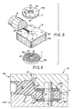
- a mold 40 for example, the two shells 41A, 41B are suitable for receiving, as a composite insert, the body 11 and the washers 19A, 19B, forming, around the assembly, an imprint 42, which, in communication with an injection channel 43, is suitable for the formation of the protective sheath 20.
- the mold 40 further comprises a core 44, forming a drawer, suitable for being engaged in the central opening 26 of the washers 19A, 19B, extending from one to the other of the shells 41A, 41B.
- the washers 19A, 19B are attached to the body 11 before the assembly is placed in the mold 40, and, so that the corresponding assembly is relatively effective, a slight conical draft is given to the cylindrical surface outside of the flange 24 of these washers 19A, 19B, so that they are placed on the connection ring 14 of this body 11 with a slight tightening of this flange 24 in the terminal hole 15 of this connection ring 14.
- the core 44 is engaged in the washers 19A, 19B of this assembly, and, as is easy to understand, the chamfer 25 which presents externally around their central opening 26 these washers 19A, 19B facilitates this engagement.
- the mold 40 is in practice mounted on an injection press of the usual type, and, preferably, it is a multi-cavity mold, for satisfactory productivity.
- the shells 41A, 41B which constitute it each have respectively bearing surfaces 44A, 44B by which they are adapted to come to bear on the washers 19A, 19B, so that, when it is closed in press on the composite insert to which these washers 19A, 19B belong, these are applied under pressure to the connection ring 14.
- the shells 41A, 41B of the mold 40 enclose the tubular barrel 12, until close tightly on the assembly.
- This synthetic material which is chosen to preferably have qualities of moldability, non-atmospheric aging, insulation, impact resistance, and non-cracking during molding, and which, as indicated above, is for example a polychloride of vinyl, completely fills the impression 42 under pressure.
- the synthetic material thus injected does not extend beyond the indentation 28 of larger diameter of the washers 19A, 19B, and, in any event, if a slight infiltration occurs. beyond this indentation 28, this infiltration cannot harm the transfer of current to be carried out between these washers 19A, 19B and the connection ring 14, since this electrical transfer is carried out by the nesting of form established for this purpose between these components.
- the synthetic material injected encircles by their edge T the washers 19A, 19B, forming around each of these, in line with their chamfer 30, a retaining ring 45.
- the injected synthetic material gains, by the channel 36, the volume left free between the core 44 and the inner surface of the terminal hole 15 of the connection ring 14, this terminal hole 15 having a diameter greater than that of the central opening 26 of the washers 19A, 19B.
- the terminal 10 according to the invention is clamped, in the usual way, on the connection terminal of any electrical apparatus to be connected to the corresponding cable.
- this tightening can only maintain, or even reinforce, the electrical contact between the washers 19A, 19B and the connection ring 14 of the bi-metallic electrical fittings 18A, 18A which this terminal comprises. 10, the force corresponding to such tightening being exerted in the same direction as that for which these washers 19A, 19B are urged into penetration relative to this connection ring 14.
- the production of the terminal 10 according to the invention is advantageously made from a common and homogeneous terminal body and from two washers which are easily achievable by cutting, cutting or press forming, the assembly being treated in the form of a composite insert by conventional overmolding in an injecting press of the usual type, in a single operation, and without any recovery after overmolding.
- the terminal according to the invention is therefore relatively simple and economical to produce, and, since its components have not been subject to any recovery, it is not liable to possible mechanical failure.
- the protective sheath 20 extends over the entire tubular barrel 12, further forming beyond thereof, a tubular extension 50 with the aid of which a plug 51 is established, the bottom 52 of which, forming a lip, is capable of allowing the stripped end of such a cable to pass, while its side wall 53 is suitable for engaging on the insulating sheath thereof, and a ring 55, which, being more rigid, and forming a spacer, is suitable for maintaining this plug 51.
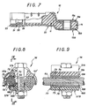
- FIGS. 8 and 9 illustrate, again by way of example, the application of the invention to a connector 56.
- this connector 56 is of the type comprising two jaws 57A, 57B suitable for defining at least one elongated channel 59, for their tightening on a bare cable 60.
- these jaws 57A, 57B form, between them, parallel to one another, two elongated channels 59, 59 ′, for their joint tightening on two bare cables 60, 60 ′.
- the bare cable 60 is made of copper or a copper alloy
- the bare cable 60 ′ which is to be electrically connected to the previous one is made of aluminum or aluminum alloy.
- the jaws 57A, 57B are also made of aluminum or aluminum alloy, so that they can cooperate directly in electrical contact with the bare cable 60 ′.
- these bi-metallic electrical connections 18A, 18B comprise, as support component, the corresponding jaw 57A, 57B.
- They further comprise, as a contact component, a plate 69A, 69B applied to such a jaw 57A, 57B and of edge T, with a protective sheath 70, which, while leaving free access to at least a portion of the surface of such a plate 69A, 69B, is engaged with at least part of such a jaw 57A, 57B.
- the plates 69A, 69B are bent to the profile of the corresponding channel 59.
- these plates 59A, 59B have, longitudinally, projecting on their lower surface, or inner, which is the contact face with the jaws 57A, 57B, a plurality of indentations 78, by which, by simple penetration, they are engaged with housings 79 formed in hollow on these jaws 57A, 57B.
- these indentations 78 extend parallel to the direction of elongation of the corresponding channel 59.
- the present invention is moreover not limited to the embodiments described and shown, but encompasses any variant embodiment and / or combination of their various elements.
- indentations when indentations are provided between the two components of a bi-metallic electrical connection according to the invention, these indentations can equally affect one and / or the other of these components.
- the surface portion of the element contact left free by the protective sheath is not necessarily flat and / or smooth.
- the field of application of the invention is not limited either to that of the lugs and connectors with reference to which it has been more particularly described, but it extends more generally to that of all organs or products using a bi-metallic electrical connection.
Landscapes
- Connections Effected By Soldering, Adhesion, Or Permanent Deformation (AREA)
- Coupling Device And Connection With Printed Circuit (AREA)
- Connector Housings Or Holding Contact Members (AREA)
- Details Of Connecting Devices For Male And Female Coupling (AREA)
Claims (21)
- Bimetallische elektrische Verbindung, die ihrer Art nach einerseits unter gegenseitiger Festlegung aneinander ein Teil (19A,19B,69A,69B) aus einem den elektrischen Strom leitenden metallischen Werkstoff einer ersten Sorte, im folgenden der Einfachheit halber Kontaktteil genannt, und ein Teil (14,57A,57B) aus einem den elektrischen Strom leitenden metallischen Werkstoff einer von der ersten verschiedenen zweiten Sorte, im folgenden der Einfachheit halber Trägerteil genannt, und andererseits eine Schutzhülle (20,70), die einen freien Zugang zu mindestens einem Teilbereich der Oberfläche des Kontaktteils (19A,19B,69A,69B) offenläßt und die mit mindestens einem Teilbereich des Trägerteils (14,57A,57B) in Eingriff steht, indem sie den Rand (22A,22B) der Übergangszone (23A, 23B), an der die Teile (19A,19B,69A,69B - 14,57A,57B) aneinander festgelegt sind, bedeckt, aufweist, dadurch gekennzeichnet, daß das durch eine Scheibe oder eine Platte gebildete Kontaktteil (19A,19B,69A,69B) mit seinem Rand (T) in die Schutzhülle (20,70) eingelassen ist.
- Bimetallische elektrische Verbindung nach Anspruch 1, dadurch gekennzeichnet, daß das Kontaktteil (19A,19B,69A,69B) längs seines von der Schutzhülle (20,70) freigelassenen Oberflächenbereichs eine abgefaste Kante (30) und längs des Randes (22A,22B) der Übergangszone (23A,23B) mit dem Trägerteil (14,57A,57B) eine weitere abgefaste Kante (23) aufweist, die mit der ersten auf seinem Rand (T) eine Schnittkante (33) bildet.
- Bimetallische elektrische Verbindung nach Anspruch 2, dadurch gekennzeichnet, daß die abgefaste Kante (32) des Kontaktteils (19A,19B,69A,69B) mit dem Trägerteil (14,57A,57B) eine Keilzone (34A,34B) begrenzt, mit welcher die Schutzhülle (20,70) in Eingriff steht.
- Bimetallische elektrische Verbindung nach einem der Ansprüche 1 bis 3, dadurch gekennzeichnet, daß die Schutzhülle (20,70) aufgeformt ist.
- Bimetallische elektrische Verbindung nach einem der Ansprüche 1 bis 4, dadurch gekennzeichnet, daß die Übergangszone (23A,23B) zwischen den beiden Teilen (19A,19B,69A,69B - 14,57A,57B) eine Formverzahnung deren einen bezüglich deren anderen aufweist.
- Bimetallische elektrische Verbindung nach Anspruch 5, dadurch gekennzeichnet, daß die von der Übergangszone (23A,23B) zwischen den beiden Teilen (19A,19B,69A,69B - 14,57A,57B) gebildete Formverzahnung darauf beruht, daß eines dieser Teile mindestens eine vorspringende Ausbuchtung (28,78) aufweist und durch diese Ausbuchtung (28,78) mit einer Aufnahme (29,79) in Eingriff steht, die in komplimentärer Weise vertieft an dem anderen der Teile (19A,19B,69A,69B - 14, 57A,57B) vorhanden ist.
- Bimetallische elektrische Verbindung nach Anspruch 6, dadurch gekennzeichnet, daß die an einem der Teile (19A,19B,69A,69B - 14,57A,57B) vertieft vorhandene Aufnahme (29,79) aus einer Zwangsverformung durch die entsprechende Ausbuchtung (28,78) des anderen der Teile (19A,19B,69A,69B - 14,57A,57B) bei der gegenseitigen Festlegung dieser Teile (19A,19B,69A,69B - 14,57A,57B) aneinander hervorgegangen ist.
- Bimetallische elektrische Verbindung nach einem der Ansprüche 6, 7, dadurch gekennzeichnet, daß das mindestens eine vorspringende Ausbuchtung (28,78) aufweisende Teil (19A,19B,69A,69B) dasjenige Teil ist, dessen Ausgangsmaterial das härtere ist.
- Bimetallische elektrische Verbindung nach einem der Ansprüche 1 bis 8, dadurch gekennzeichnet, daß die Schutzhülle (20,70) aus einem gegenüber atmosphärischen Agenzien inerten Werkstoff besteht.
- Bimetallische elektrische Verbindung nach Anspruch 9, dadurch gekennzeichnet, daß die Schutzhülle (20,70) aus einem gegenüber elektrischem Strom isolierenden Werkstoff besteht.
- Bimetallische elektrische Verbindung nach einem der Ansprüche 1 bis 10, dadurch gekennzeichnet, daß sie in Zugehörigkeit zu einem Kabelschuh (10) als Trägerteil die Anschlußöse (14) dieses Kabelschuhs (10) und als Kontaktteil eine an der Anschlußöse (14) rund um dessen Anschlußloch (15) angeordnete Scheibe (19A,19B) aufweist.
- Bimetallische elektrische Verbindung nach Anspruch 11, dadurch gekennzeichnet, daß die das Kontaktteil bildende Scheibe (19A,19B) längs ihres Innenumfangs von ihrer Innenseite vorspringend einen durchgezogenen Rand (24) aufweist, durch den sie mit dem Anschlußloch (15) der Anschlußöse (14) in Eingriff steht.
- Bimetallische elektrische Verbindung nach einem der Ansprüche 11, 12, dadurch gekennzeichnet, daß die das Kontaktteil bildende Scheibe (19A,19B) an ihrer Innenseite vorspringend um ihre zentrale Öffnung (26) herum ringförmig angeordnet mehrere konzentrische Ausbuchtungen (28) aufweist.
- Bimetallische elektrische Verbindung nach Anspruch 13, dadurch gekennzeichnet, daß die den größten Durchmesser aufweisende Ausbuchtung (28) in unmittelbarer Nachbarschaft des äußeren Umfangs der Scheibe (19A,19B) angeordnet ist.
- Bimetallische elektrische Verbindung nach einem der Ansprüche 11 bis 14, dadurch gekennzeichnet, daß die das Trägerteil bildende Anschlußöse (14) an seiner Oberfläche vertieft eine Rinne (36) aufweist, die sich von deren Anschlußloch (15) aus und in dieses einmündend radial erstreckt und die über den äußeren Umfang der das Kontaktteil bildenden Scheibe (19A,19B) hinausgeht und die Schutzhülle (20) sich mittels dieser Rinne (36) zusammenhängend auf die Oberfläche des Anschlußloches (15) erstreckt.
- Bimetallische elektrische Verbindung nach einem der Ansprüche 11 bis 14, dadurch gekennzeichnet, daß sie eine ein Kontaktteil bildende Scheibe (19A,19B) auf beiden Seiten (16A,16B) der das Trägerteil bildenden Anschlußöse (14) aufweist.
- Bimetallische elektrische Verbindung nach einem der Ansprüche 11 bis 16, dadurch gekennzeichnet, daß die das Trägerteil bildende Anschlußöse (14) einen daran festgelegten Schaft (12) aufweist, der mindestens an seinem Ende rohrförmig ist, wobei sich die Schutzhülle (20) mindestens auf einem Teil dieses rohrförmigen Schaftes (12) erstreckt.
- Bimetallische elektrische Verbindung nach einem der Ansprüche 1 bis 10, dadurch gekennzeichnet, daß in Zugehörigkeit zu einem Verbinder (56) mit mindestens zwei Klemmbacken (57A,57B), zwischen denen mindestens ein länglicher Kanal (59,59') begrenzbar ist, sein Trägerteil durch eine der Klemmbacken 57A,57B und sein Kontaktteil durch ein an dieser Klemmbacke (57A,57B) festgelegtes Plättchen (69A,69B) gebildet ist.
- Bimetallische elektrische Verbindung nach Anspruch 18, dadurch gekennzeichnet, daß das das Kontaktteil bildende Plättchen (69A,69B) auf das Profil des betreffenden Kanals (59,59') aufgewölbt ist.
- Bimetallische elektrische Verbindung nach einem der Ansprüche 18, 19, dadurch gekennzeichnet, daß das das Kontaktteil bildende Plättchen (57A,57B) an seiner inneren Oberfläche in der Längsrichtung vorspringend eine Anzahl paralleler Ausbuchtungen (78) aufweist.
- Verfahren zur Herstellung einer bimetallischen elektrischen Verbindung, das darin besteht, im Zuge ein und desselben Vorgangs einerseits eine gegenseitige Festlegung durch Anpressung von zwei Teilen (19A,19B,69A,69B - 14,57A,57B), deren eines aus einem den elektrischen Strom leitenden metallischen Werkstoff einer ersten Sorte besteht, während das andere aus einem den elektrischen Strom leitenden metallischen Werkstoff einer von der ersten verschiedenen zweiten Sorte besteht und von denen eines an seiner Seite des Kontaktes mit dem anderen vorspringend mindestens eine Ausbuchtung (28,78) aufweist, und andererseits das Aufformen einer Schutzhülle (20,70) auf das Ganze, die einen freien Zugang zu mindestens einem Teil der Oberfläche eines der Teile (19A,19B,69A,69B - 14,57A,57B) freiläßt und gleichzeitig dessen Einpackung durch Einfassen mittels seines Randes (T) sicherstellt, wobei das Teil die Form einer Scheibe oder einer Platte aufweist, und die mit mindestens einem Teilbereich des anderen der Teile (19A,19B, 69A,69B - 14,57A,57B) in Eingriff steht, indem sie den Rand (22A,22B) der Übergangszone (23A,23B) bedeckt, an der die Teile (19A, 19B,69A,69B - 14,57A,57B) gegenseitig aneinander festgelegt sind, zu bewerkstelligen.
Priority Applications (1)
| Application Number | Priority Date | Filing Date | Title |
|---|---|---|---|
| AT88400877T ATE79698T1 (de) | 1987-04-17 | 1988-04-12 | Elektrische verbindung aus bimetall und verfahren zur herstellung einer solchen verbindung. |
Applications Claiming Priority (2)
| Application Number | Priority Date | Filing Date | Title |
|---|---|---|---|
| FR8705536A FR2614138B1 (fr) | 1987-04-17 | 1987-04-17 | Raccord electrique bi-metallique, et procede pour la realisation d'un tel raccord |
| FR8705536 | 1987-04-17 |
Publications (2)
| Publication Number | Publication Date |
|---|---|
| EP0287453A1 EP0287453A1 (de) | 1988-10-19 |
| EP0287453B1 true EP0287453B1 (de) | 1992-08-19 |
Family
ID=9350274
Family Applications (1)
| Application Number | Title | Priority Date | Filing Date |
|---|---|---|---|
| EP88400877A Expired - Lifetime EP0287453B1 (de) | 1987-04-17 | 1988-04-12 | Elektrische Verbindung aus Bimetall und Verfahren zur Herstellung einer solchen Verbindung |
Country Status (4)
| Country | Link |
|---|---|
| EP (1) | EP0287453B1 (de) |
| AT (1) | ATE79698T1 (de) |
| DE (1) | DE3873806T2 (de) |
| FR (1) | FR2614138B1 (de) |
Family Cites Families (1)
| Publication number | Priority date | Publication date | Assignee | Title |
|---|---|---|---|---|
| IL31854A (en) * | 1968-04-12 | 1972-07-26 | Amp Inc | Terminals for weld connection to electrical conductor wires |
-
1987
- 1987-04-17 FR FR8705536A patent/FR2614138B1/fr not_active Expired
-
1988
- 1988-04-12 AT AT88400877T patent/ATE79698T1/de not_active IP Right Cessation
- 1988-04-12 EP EP88400877A patent/EP0287453B1/de not_active Expired - Lifetime
- 1988-04-12 DE DE8888400877T patent/DE3873806T2/de not_active Expired - Fee Related
Also Published As
| Publication number | Publication date |
|---|---|
| FR2614138B1 (fr) | 1989-07-07 |
| ATE79698T1 (de) | 1992-09-15 |
| DE3873806T2 (de) | 1993-04-01 |
| DE3873806D1 (de) | 1992-09-24 |
| EP0287453A1 (de) | 1988-10-19 |
| FR2614138A1 (fr) | 1988-10-21 |
Similar Documents
| Publication | Publication Date | Title |
|---|---|---|
| EP0170545B2 (de) | Isolierter Abzweigverbinder für elektrische Kabel | |
| EP2198483A2 (de) | Anschluss für elektrische verbindung und zusammenbauverfahren dafür | |
| FR2762455A1 (fr) | Piece de raccordement etanche d'un tube a l'orifice d'une paroi | |
| FR3032947A1 (fr) | Bouchons d'etancheite , assemblage et methode pour etancheifier une ouverture | |
| FR2763437A1 (fr) | Dispositif d'entree de cable | |
| EP2273618A1 (de) | Anschlussvorrichtung zum crimpen ein elektrisches Kabel und Herstellungsverfahren für eine solche Vorrichtung. | |
| FR2601516A2 (fr) | Connecteur de derivation isole pour cables electriques | |
| EP0335772B1 (de) | Kabelendstück | |
| WO2015118401A1 (fr) | Gaine tubulaire annelée comportant un moyen intérieur de serrage | |
| EP1089411B1 (de) | Vorrichtung bestimmt zur abgedichten Durchbohrung mit einem zylindrischen Objekt, Dose für ein elektrisches Gerät und Verfahren dafür | |
| EP0348269B1 (de) | Kabelschuh und Herstellungsverfahren | |
| EP0287453B1 (de) | Elektrische Verbindung aus Bimetall und Verfahren zur Herstellung einer solchen Verbindung | |
| EP1383202A1 (de) | Verbindungsanordnung zwischen Kabel und Kontaktelement | |
| FR2543369A2 (fr) | Dispositif d'etancheite pour connecteur electrique | |
| FR2623024A1 (fr) | Connecteur auto-denudant pour conducteur electrique isole | |
| FR2747244A1 (fr) | Entree de cable ou de canalisation a montage rapide | |
| FR2490878A1 (fr) | Systeme d'etancheite, a l'egard des gaz et des liquides et par rapport a un couvercle en matiere plastique, de la chemise de borne metallique d'un accumulateur | |
| EP0122197A2 (de) | Verankerungsvorrichtungen für eingefettete Spannglieder | |
| EP4203214A1 (de) | Vorrichtung zur installation eines geschäumten rohrförmigen teils auf elektrischen kabeln und verfahren dafür | |
| FR2780556A1 (fr) | Accessoire de branchement pour cable derive a raccorder a un cable principal, et connecteur de derivation equipe d'un tel accessoire de branchement | |
| FR2884974A1 (fr) | Raccord de cables a ame conductrice sur cosses electriques | |
| FR2806683A1 (fr) | Baguette de protection pour carrosserie de vehicule automobile | |
| FR3104838A1 (fr) | Ensemble de protection pour au moins un câble | |
| FR2724780A1 (fr) | Bague support de conducteurs electriques destinee a etre utilisee pour la traversee de cloisons | |
| FR2479545A2 (fr) | Manchon pour proteger l'epissure de cables electriques ou telephoniques |
Legal Events
| Date | Code | Title | Description |
|---|---|---|---|
| PUAI | Public reference made under article 153(3) epc to a published international application that has entered the european phase |
Free format text: ORIGINAL CODE: 0009012 |
|
| AK | Designated contracting states |
Kind code of ref document: A1 Designated state(s): AT BE CH DE ES GB GR IT LI LU NL SE |
|
| 17P | Request for examination filed |
Effective date: 19881128 |
|
| 17Q | First examination report despatched |
Effective date: 19910319 |
|
| GRAA | (expected) grant |
Free format text: ORIGINAL CODE: 0009210 |
|
| AK | Designated contracting states |
Kind code of ref document: B1 Designated state(s): AT BE CH DE ES GB GR IT LI LU NL SE |
|
| PG25 | Lapsed in a contracting state [announced via postgrant information from national office to epo] |
Ref country code: SE Free format text: THE PATENT HAS BEEN ANNULLED BY A DECISION OF A NATIONAL AUTHORITY Effective date: 19920819 Ref country code: NL Effective date: 19920819 Ref country code: GR Free format text: LAPSE BECAUSE OF FAILURE TO SUBMIT A TRANSLATION OF THE DESCRIPTION OR TO PAY THE FEE WITHIN THE PRESCRIBED TIME-LIMIT Effective date: 19920819 Ref country code: GB Effective date: 19920819 Ref country code: ES Free format text: THE PATENT HAS BEEN ANNULLED BY A DECISION OF A NATIONAL AUTHORITY Effective date: 19920819 Ref country code: AT Effective date: 19920819 |
|
| REF | Corresponds to: |
Ref document number: 79698 Country of ref document: AT Date of ref document: 19920915 Kind code of ref document: T |
|
| REF | Corresponds to: |
Ref document number: 3873806 Country of ref document: DE Date of ref document: 19920924 |
|
| ITF | It: translation for a ep patent filed | ||
| NLV1 | Nl: lapsed or annulled due to failure to fulfill the requirements of art. 29p and 29m of the patents act | ||
| GBV | Gb: ep patent (uk) treated as always having been void in accordance with gb section 77(7)/1977 [no translation filed] |
Effective date: 19920819 |
|
| PG25 | Lapsed in a contracting state [announced via postgrant information from national office to epo] |
Ref country code: LU Free format text: LAPSE BECAUSE OF NON-PAYMENT OF DUE FEES Effective date: 19930430 Ref country code: LI Effective date: 19930430 Ref country code: CH Effective date: 19930430 Ref country code: BE Effective date: 19930430 |
|
| PLBE | No opposition filed within time limit |
Free format text: ORIGINAL CODE: 0009261 |
|
| STAA | Information on the status of an ep patent application or granted ep patent |
Free format text: STATUS: NO OPPOSITION FILED WITHIN TIME LIMIT |
|
| 26N | No opposition filed | ||
| BERE | Be: lapsed |
Owner name: SOC. INDUSTRIELLE DE CONSTRUCTION D'APPAREILS ET D Effective date: 19930430 |
|
| REG | Reference to a national code |
Ref country code: CH Ref legal event code: PL |
|
| PGFP | Annual fee paid to national office [announced via postgrant information from national office to epo] |
Ref country code: DE Payment date: 19990630 Year of fee payment: 12 |
|
| PG25 | Lapsed in a contracting state [announced via postgrant information from national office to epo] |
Ref country code: DE Free format text: LAPSE BECAUSE OF NON-PAYMENT OF DUE FEES Effective date: 20010201 |
|
| PG25 | Lapsed in a contracting state [announced via postgrant information from national office to epo] |
Ref country code: IT Free format text: LAPSE BECAUSE OF NON-PAYMENT OF DUE FEES;WARNING: LAPSES OF ITALIAN PATENTS WITH EFFECTIVE DATE BEFORE 2007 MAY HAVE OCCURRED AT ANY TIME BEFORE 2007. THE CORRECT EFFECTIVE DATE MAY BE DIFFERENT FROM THE ONE RECORDED. Effective date: 20050412 |